Page 1905 of 2395

RHA094GB
SYSTEM DESCRIPTION=NBHA0066Auto amplifier controls compressor operation by ambient tempera-
ture and signal from ECM.
Low Temperature Protection ControlNBHA0066S01Auto amplifier will turn the compressor ªONº or ªOFFº as deter-
mined by a signal detected by ambient sensor.
When ambient temperatures are greater than ±2ÉC (28ÉF), the
compressor turns ªONº. The compressor turns ªOFFº when ambi-
ent temperatures are less than þ5ÉC (23ÉF).
RHA877H
DIAGNOSTIC PROCEDURENBHA0067SYMPTOM: Magnet clutch does not engage when AUTO
switch is ON.
1 CHECK POWER SUPPLY FOR COMPRESSOR
Disconnect compressor harness connector. Do approx. 12 volts exist between compressor harness terminal No. 1 and
body ground?
RHA096G
YesorNo
Ye s©Check magnet clutch coil.
1. If NG, replace magnet clutch. Refer to HA-150.
2. Go to self-diagnosis step-by-step procedure (HA-45) and perform self-diagnosis STEP
4.
Confirm that magnet clutch operation is normal.
No©Disconnect A/C relay. And GO TO 2.
TROUBLE DIAGNOSES
Magnet Clutch (Cont'd)
HA-106
Page 1906 of 2395

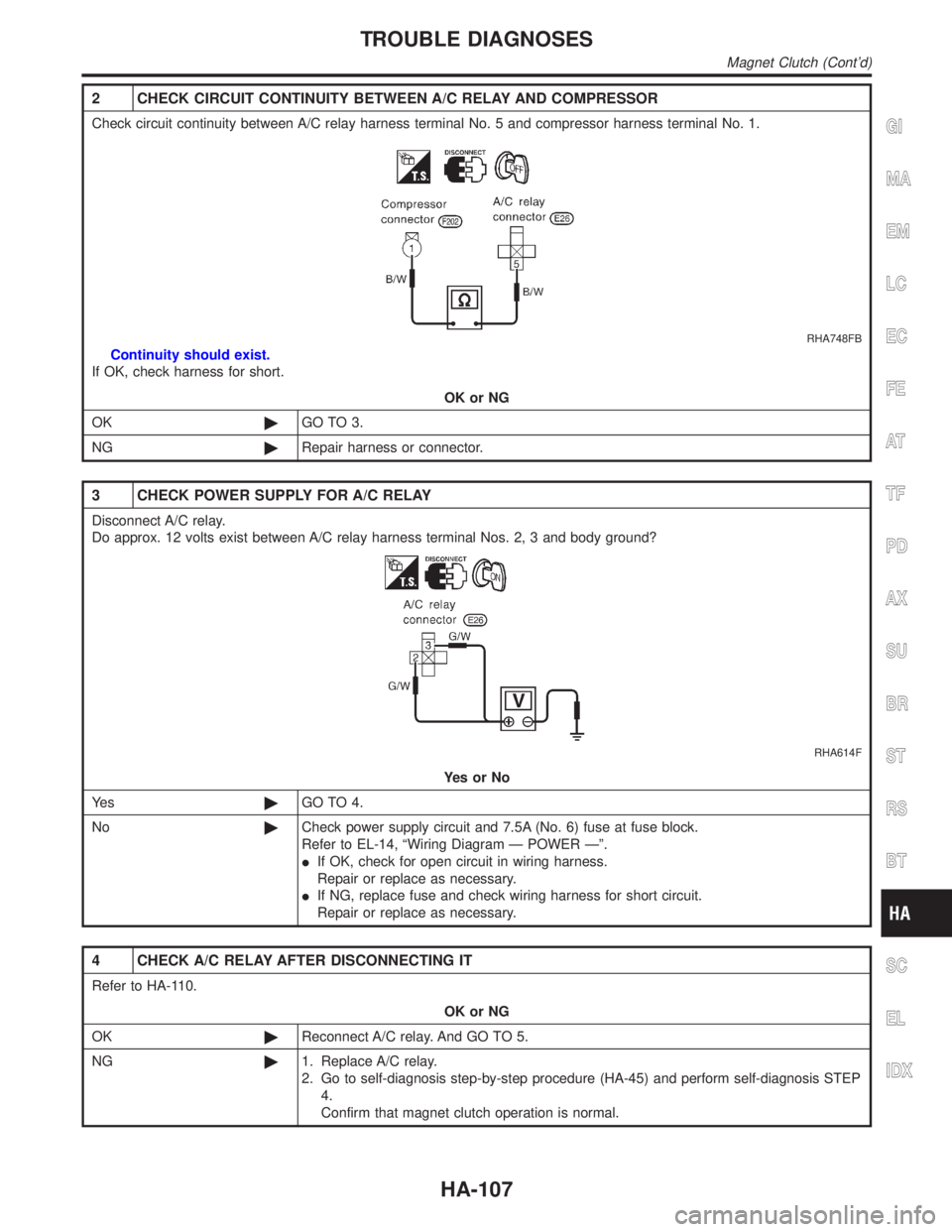
2 CHECK CIRCUIT CONTINUITY BETWEEN A/C RELAY AND COMPRESSOR
Check circuit continuity between A/C relay harness terminal No. 5 and compressor harness terminal No. 1.
RHA748FB
Continuity should exist.
If OK, check harness for short.
OK or NG
OK©GO TO 3.
NG©Repair harness or connector.
3 CHECK POWER SUPPLY FOR A/C RELAY
Disconnect A/C relay.
Do approx. 12 volts exist between A/C relay harness terminal Nos. 2, 3 and body ground?
RHA614F
YesorNo
Ye s©GO TO 4.
No©Check power supply circuit and 7.5A (No. 6) fuse at fuse block.
Refer to EL-14, ªWiring Diagram Ð POWER к.
IIf OK, check for open circuit in wiring harness.
Repair or replace as necessary.
IIf NG, replace fuse and check wiring harness for short circuit.
Repair or replace as necessary.
4 CHECK A/C RELAY AFTER DISCONNECTING IT
Refer to HA-110.
OK or NG
OK©Reconnect A/C relay. And GO TO 5.
NG©1. Replace A/C relay.
2. Go to self-diagnosis step-by-step procedure (HA-45) and perform self-diagnosis STEP
4.
Confirm that magnet clutch operation is normal.
GI
MA
EM
LC
EC
FE
AT
TF
PD
AX
SU
BR
ST
RS
BT
SC
EL
IDX
TROUBLE DIAGNOSES
Magnet Clutch (Cont'd)
HA-107
Page 1907 of 2395
5 CHECK COIL SIDE CIRCUIT OF A/C RELAY
Do approx. 12 volts exist between ECM harness terminal No. 27 and body ground?
RHA482GG
YesorNo
Ye s©GO TO 6.
No©Disconnect A/C relay.
Disconnect ECM harness connector.
GO TO 11.
6 CHECK VOLTAGE FOR ECM
Do approx. 12 volts exist between ECM harness terminal No. 45 and body ground?
RHA701FJ
YesorNo
Ye s©Disconnect ECM harness connector.
Disconnect dual-pressure switch harness connector.
GO TO 7.
No©Check ECM. Refer to EC-127, ªECM Terminals and Reference Valueº.
TROUBLE DIAGNOSES
Magnet Clutch (Cont'd)
HA-108
Page 1908 of 2395
7 CHECK CIRCUIT CONTINUITY BETWEEN ECM AND AUTO AMP.
Check circuit continuity between ECM harness terminal No. 45 and auto amp. harness terminal No. 22.
RHA878H
Continuity should exist.
If OK, check harness for short.
OK or NG
OK©GO TO 8.
NG©1. Repair harness or connector.
2. Go to ªSTEP-BY-STEP PROCEDUREº, ªSelf-diagnosisº, HA-45 and perform self-diag-
nosis STEP 4.
Confirm that magnet clutch operation is normal.
8 CHECK REFRIGERANT PRESSURE SENSOR
Refer to EC-641, ªDiagnostic Procedureº, HA-111.
OK or NG
OK©GO TO 9.
NG©Replace refrigerant pressure sensor.
9 CHECK VOLTAGE FOR ECM
Check 4.6 volts exist between ECM harness terminal No. 51 and body ground?
RHA482GG
YesorNo
Ye s©Check ECM. Refer to EC-127, ªECM Terminal and Reference Valueº.
No©GO TO 10.
GI
MA
EM
LC
EC
FE
AT
TF
PD
AX
SU
BR
ST
RS
BT
SC
EL
IDX
TROUBLE DIAGNOSES
Magnet Clutch (Cont'd)
HA-109
Page 1909 of 2395
10 CHECK CIRCUIT CONTINUITY BETWEEN ECM AND AUTO AMP.
Check circuit continuity between ECM harness terminal No. 51 and auto amp. harness terminal No. 6 (17).
RHA879H
Continuity should exist.
If OK, check harness for short.
OK or NG
OK©Replace auto amp.
NG©1. Repair harness or connector.
2. Go to ªSTEP-BY-STEP PROCEDUREº, ªSelf-diagnosisº, HA-45 and perform self-diag-
nosis STEP 4.
Confirm that magnet clutch operation is normal.
11 CHECK CIRCUIT CONTINUITY BETWEEN A/C RELAY AND ECM
Check circuit continuity between A/C relay harness terminal No. 1 and ECM harness terminal No. 27.
RHA474GB
Continuity should exist.
OK or NG
OK©Check harness for short.
NG©Repair harness or connector.
SEF090M
COMPONENT INSPECTIONNBHA0068A/C RelayNBHA0068S01Check continuity between terminal Nos. 3 and 5.
Conditions Continuity
12V direct current supply between terminal Nos. 1 and 2 Yes
No current supply No
If NG, replace relay.
TROUBLE DIAGNOSES
Magnet Clutch (Cont'd)
HA-110
Page 1910 of 2395
RHA880H
SHA315F
Refrigerant Pressure SensorNBHA0068S02Make sure that higher A/C refrigerant pressure results in higher
refrigerant-pressure sensor output voltage.
GI
MA
EM
LC
EC
FE
AT
TF
PD
AX
SU
BR
ST
RS
BT
SC
EL
IDX
TROUBLE DIAGNOSES
Magnet Clutch (Cont'd)
HA-111
Page 1949 of 2395
Compressor Clutch
OVERHAULNBHA0073
RHA122F
RHA136EB
REMOVALNBHA0074IWhen removing center bolt, hold clutch disc with clutch disc
wrench.
RHA399F
RHA124F
IRemove the clutch disc using the clutch disc puller.
Insert the holder's three pins into the holes in the clutch disc.
Rotate the holder clockwise to hook it onto the plate. Then,
tighten the center bolt to remove the clutch disc.
After removing the clutch disc, remove the shims from either
the drive shaft or the clutch disc.
SERVICE PROCEDURE
Compressor Clutch
HA-150
Page 1950 of 2395

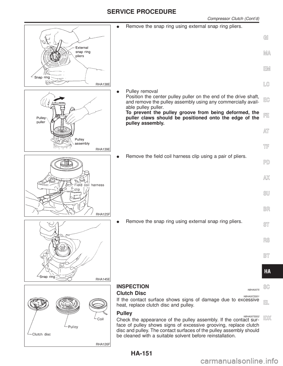
RHA138E
IRemove the snap ring using external snap ring pliers.
RHA139E
IPulley removal
Position the center pulley puller on the end of the drive shaft,
and remove the pulley assembly using any commercially avail-
able pulley puller.
To prevent the pulley groove from being deformed, the
puller claws should be positioned onto the edge of the
pulley assembly.
RHA125F
IRemove the field coil harness clip using a pair of pliers.
RHA145E
IRemove the snap ring using external snap ring pliers.
RHA126F
INSPECTIONNBHA0075Clutch DiscNBHA0075S01If the contact surface shows signs of damage due to excessive
heat, replace clutch disc and pulley.
PulleyNBHA0075S02Check the appearance of the pulley assembly. If the contact sur-
face of pulley shows signs of excessive grooving, replace clutch
disc and pulley. The contact surfaces of the pulley assembly should
be cleaned with a suitable solvent before reinstallation.
GI
MA
EM
LC
EC
FE
AT
TF
PD
AX
SU
BR
ST
RS
BT
SC
EL
IDX
SERVICE PROCEDURE
Compressor Clutch (Cont'd)
HA-151