Page 267 of 2395
9 CHECK THROTTLE POSITION SWITCH CIRCUIT (Without CONSULT-II)
Without CONSULT-II
1. Turn ignition switch to ªONº position.
(Do not start engine.)
2. Check voltage between TCM terminals 16, 17 and ground while depressing, and releasing accelerator pedal slowly.
(after warming up engine)
[Refer to ªPreparationº, ªTCM SELF-DIAGNOSTIC PROCEDURE (No Tools)º, AT-46.]
MTBL0519
SAT526J
OK or NG
OK©GO TO 10.
NG©GO TO 8.
10 CHECK DTC
Perform Diagnostic procedure, AT-258.
OK or NG
OK©INSPECTION END
NG©GO TO 11.
11 CHECK TCM INSPECTION
1. Perform TCM input/output signal inspection.
2. If NG, recheck TCM pin terminals for damage or loose connection with harness connector.
OK or NG
OK©INSPECTION END
NG©Repair or replace damaged parts.
TROUBLE DIAGNOSES FOR SYMPTOMS
21. TCM Self-diagnosis Does Not Activate (PNP, Overdrive Control and Throttle Position Switches Circuit Checks) (Cont'd)
AT-262
Page 272 of 2395
Diagnostic ProcedureNBAT0095SYMPTOM 1:
ISelector lever cannot be moved from ªPº position with key
in ªONº position and brake pedal applied.
ISelector lever can be moved from ªPº position with key in
ªONº position and brake pedal released.
ISelector lever can be moved from ªPº position when key
is removed from key cylinder.
SYMPTOM 2:
Ignition key cannot be removed when selector lever is set to
ªPº position. It can be removed when selector lever is set to
any position except ªPº.
1 CHECK KEY INTERLOCK CABLE
Check key interlock cable for damage.
OK or NG
OK©GO TO 2.
NG©Repair key interlock cable. Refer to ªKey Interlock Cableº, AT-271.
2 CHECK SELECTOR LEVER POSITION
Check selector lever position for damage.
OK or NG
OK©GO TO 3.
NG©Check selector lever. Refer to ªON-VEHICLE SERVICE Ð PNP Switch and Manual Con-
trol Linkage Adjustmentº, AT-276 and AT-276.
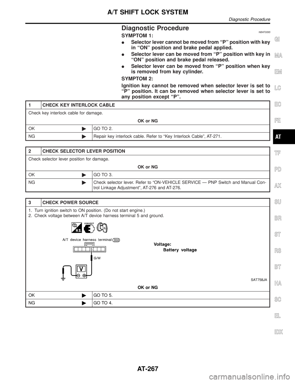
3 CHECK POWER SOURCE
1. Turn ignition switch to ON position. (Do not start engine.)
2. Check voltage between A/T device harness terminal 5 and ground.
SAT758JA
OK or NG
OK©GO TO 5.
NG©GO TO 4.
GI
MA
EM
LC
EC
FE
TF
PD
AX
SU
BR
ST
RS
BT
HA
SC
EL
IDX
A/T SHIFT LOCK SYSTEM
Diagnostic Procedure
AT-267
Page 275 of 2395
10 CHECK SHIFT LOCK SOLENOID
ICheck operation by applying battery voltage shift lock solenoid harness terminals 1 and 3.
SAT762J
OK or NG
OK©GO TO 11.
NG©Replace shift lock solenoid.
11 CHECK SHIFT LOCK OPERATION
1. Reconnect shift lock harness connector.
2. Turn ignition switch from OFF to ON position. (Do not start engine.)
3. Recheck shift lock operation.
OK or NG
OK©INSPECTION END
NG©GO TO 12.
12 CHECK A/T DEVICE INSPECTION
1. Perform A/T device input/output signal inspection test.
2. If NG, recheck harness connector connection.
OK or NG
OK©INSPECTION END
NG©Repair or replace damaged parts.
A/T SHIFT LOCK SYSTEM
Diagnostic Procedure (Cont'd)
AT-270
Page 279 of 2395

SAT360IA
Revolution Sensor ReplacementNBAT0210Ð 4WD MODEL ÐNBAT0210S011. Remove rear engine mounting member from side member
while supporting A/T with transfer case with jack. Tighten rear
engine mounting member to the specified torque. Refer to
EM-59, ªRear Engine Mountingº.
2. Lower A/T with transfer case as much as possible.
3. Remove revolution sensor from A/T.
4. Reinstall any part removed.
IAlways use new sealing parts.
SAT661I
Ð 2WD MODEL ÐNBAT0210S02IRemove revolution sensor from A/T.
IAlways use new sealing parts.
SAT136K
Turbine Revolution Sensor ReplacementNBAT02311. Remove A/T assembly, Refer to ªRemovalº, AT-277.
2. Remove turbine revolution sensor from A/T assembly upper
side.
3. Reinstall any part removed.
IAlways use new sealing parts.
SAT035E
Rear Oil Seal ReplacementNBAT0211Ð 4WD MODEL ÐNBAT0211S011. Remove transfer case from vehicle. Refer to TF-119, ªRemovalº.
2. Remove rear oil seal.
IDo not remove oil seal unless it is to be replaced.
3. Install rear oil seal.
IApply ATF before installing.
4. Reinstall any part removed.
ON-VEHICLE SERVICE
Revolution Sensor Replacement
AT-274
Page 280 of 2395
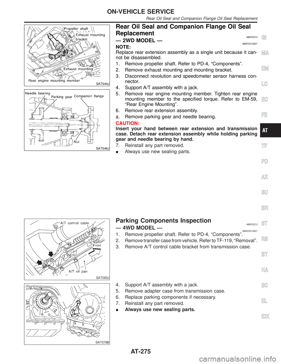
SAT544J
SAT546J
Rear Oil Seal and Companion Flange Oil Seal
Replacement
NBAT0212Ð 2WD MODEL ÐNBAT0212S01NOTE:
Replace rear extension assembly as a single unit because it can-
not be disassembled.
1. Remove propeller shaft. Refer to PD-4, ªComponentsº.
2. Remove exhaust mounting and mounting bracket.
3. Disconnect revolution and speedometer sensor harness con-
nector.
4. Support A/T assembly with a jack.
5. Remove rear engine mounting member. Tighten rear engine
mounting member to the specified torque. Refer to EM-59,
ªRear Engine Mountingº.
6. Remove rear extension assembly.
a. Remove parking gear and needle bearing.
CAUTION:
Insert your hand between rear extension and transmission
case. Detach rear extension assembly while holding parking
gear and needle bearing by hand.
7. Reinstall any part removed.
IAlways use new sealing parts.
SAT083J
Parking Components InspectionNBAT0213Ð 4WD MODEL ÐNBAT0213S011. Remove propeller shaft. Refer to PD-4, ªComponentsº.
2. Remove transfer case from vehicle. Refer to TF-119, ªRemovalº.
3. Remove A/T control cable bracket from transmission case.
SAT078B
4. Support A/T assembly with a jack.
5. Remove adapter case from transmission case.
6. Replace parking components if necessary.
7. Reinstall any part removed.
IAlways use new sealing parts.
GI
MA
EM
LC
EC
FE
TF
PD
AX
SU
BR
ST
RS
BT
HA
SC
EL
IDX
ON-VEHICLE SERVICE
Rear Oil Seal and Companion Flange Oil Seal Replacement
AT-275
Page 281 of 2395
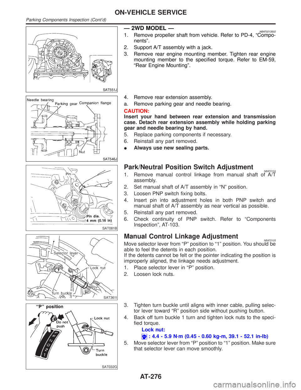
SAT551J
Ð 2WD MODEL ÐNBAT0213S021. Remove propeller shaft from vehicle. Refer to PD-4, ªCompo-
nentsº.
2. Support A/T assembly with a jack.
3. Remove rear engine mounting member. Tighten rear engine
mounting member to the specified torque. Refer to EM-59,
ªRear Engine Mountingº.
SAT546J
4. Remove rear extension assembly.
a. Remove parking gear and needle bearing.
CAUTION:
Insert your hand between rear extension and transmission
case. Detach rear extension assembly while holding parking
gear and needle bearing by hand.
5. Replace parking components if necessary.
6. Reinstall any part removed.
IAlways use new sealing parts.
SAT081B
Park/Neutral Position Switch AdjustmentNBAT01041. Remove manual control linkage from manual shaft of A/T
assembly.
2. Set manual shaft of A/T assembly in ªNº position.
3. Loosen PNP switch fixing bolts.
4. Insert pin into adjustment holes in both PNP switch and
manual shaft of A/T assembly as near vertical as possible.
5. Reinstall any part removed.
6. Check continuity of PNP switch. Refer to ªComponents
Inspectionº, AT-103.
SAT361I
Manual Control Linkage AdjustmentNBAT0105Move selector lever from ªPº position to ª1º position. You should be
able to feel the detents in each position.
If the detents cannot be felt or the pointer indicating the position is
improperly aligned, the linkage needs adjustment.
1. Place selector lever in ªPº position.
2. Loosen lock nuts.
SAT032G
3. Tighten turn buckle until aligns with inner cable, pulling selec-
tor lever toward ªRº position side without pushing button.
4. Back off turn buckle 1 turn and tighten lock nuts to the speci-
fied torque.
Lock nut:
: 4.4 - 5.9 N´m (0.45 - 0.60 kg-m, 39.1 - 52.1 in-lb)
5. Move selector lever from ªPº position to ª1º position. Make sure
that selector lever can move smoothly.
ON-VEHICLE SERVICE
Parking Components Inspection (Cont'd)
AT-276
Page 282 of 2395
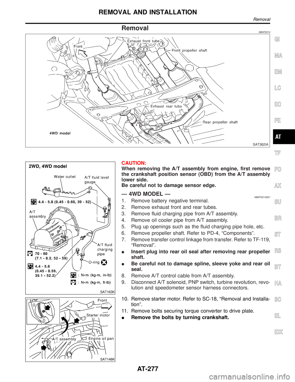
RemovalNBAT0214
SAT362IA
SAT163K
CAUTION:
When removing the A/T assembly from engine, first remove
the crankshaft position sensor (OBD) from the A/T assembly
lower side.
Be careful not to damage sensor edge.
Ð 4WD MODEL ÐNBAT0214S011. Remove battery negative terminal.
2. Remove exhaust front and rear tubes.
3. Remove fluid charging pipe from A/T assembly.
4. Remove oil cooler pipe from A/T assembly.
5. Plug up openings such as the fluid charging pipe hole, etc.
6. Remove propeller shaft. Refer to PD-4, ªComponentsº.
7. Remove transfer control linkage from transfer. Refer to TF-119,
ªRemovalº.
IInsert plug into rear oil seal after removing rear propeller
shaft.
IBe careful not to damage spline, sleeve yoke and rear oil
seal.
8. Remove A/T control cable from A/T assembly.
9. Disconnect A/T solenoid, PNP switch, turbine revolution, revo-
lution and speedometer sensor harness connectors.
SAT148K
10. Remove starter motor. Refer to SC-18, ªRemoval and Installa-
tionº.
11. Remove bolts securing torque converter to drive plate.
IRemove the bolts by turning crankshaft.
GI
MA
EM
LC
EC
FE
TF
PD
AX
SU
BR
ST
RS
BT
HA
SC
EL
IDX
REMOVAL AND INSTALLATION
Removal
AT-277
Page 283 of 2395
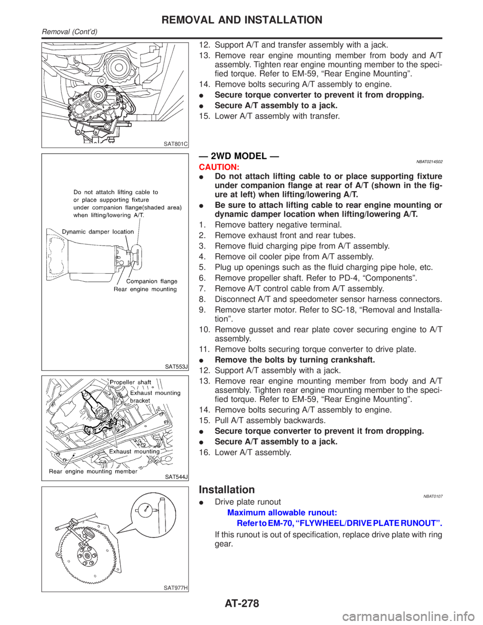
SAT801C
12. Support A/T and transfer assembly with a jack.
13. Remove rear engine mounting member from body and A/T
assembly. Tighten rear engine mounting member to the speci-
fied torque. Refer to EM-59, ªRear Engine Mountingº.
14. Remove bolts securing A/T assembly to engine.
ISecure torque converter to prevent it from dropping.
ISecure A/T assembly to a jack.
15. Lower A/T assembly with transfer.
SAT553J
SAT544J
Ð 2WD MODEL ÐNBAT0214S02CAUTION:
IDo not attach lifting cable to or place supporting fixture
under companion flange at rear of A/T (shown in the fig-
ure at left) when lifting/lowering A/T.
IBe sure to attach lifting cable to rear engine mounting or
dynamic damper location when lifting/lowering A/T.
1. Remove battery negative terminal.
2. Remove exhaust front and rear tubes.
3. Remove fluid charging pipe from A/T assembly.
4. Remove oil cooler pipe from A/T assembly.
5. Plug up openings such as the fluid charging pipe hole, etc.
6. Remove propeller shaft. Refer to PD-4, ªComponentsº.
7. Remove A/T control cable from A/T assembly.
8. Disconnect A/T and speedometer sensor harness connectors.
9. Remove starter motor. Refer to SC-18, ªRemoval and Installa-
tionº.
10. Remove gusset and rear plate cover securing engine to A/T
assembly.
11. Remove bolts securing torque converter to drive plate.
IRemove the bolts by turning crankshaft.
12. Support A/T assembly with a jack.
13. Remove rear engine mounting member from body and A/T
assembly. Tighten rear engine mounting member to the speci-
fied torque. Refer to EM-59, ªRear Engine Mountingº.
14. Remove bolts securing A/T assembly to engine.
15. Pull A/T assembly backwards.
ISecure torque converter to prevent it from dropping.
ISecure A/T assembly to a jack.
16. Lower A/T assembly.
SAT977H
InstallationNBAT0107IDrive plate runout
Maximum allowable runout:
Refer to EM-70, ªFLYWHEEL/DRIVE PLATE RUNOUTº.
If this runout is out of specification, replace drive plate with ring
gear.
REMOVAL AND INSTALLATION
Removal (Cont'd)
AT-278