Page 1643 of 2395

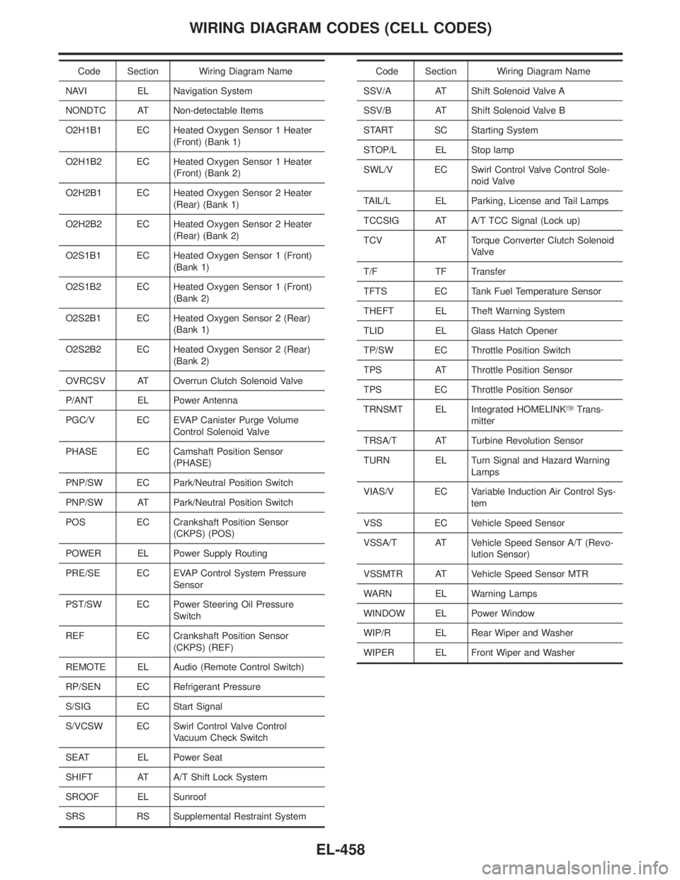
Code Section Wiring Diagram Name
NAVI EL Navigation System
NONDTC AT Non-detectable Items
O2H1B1 EC Heated Oxygen Sensor 1 Heater
(Front) (Bank 1)
O2H1B2 EC Heated Oxygen Sensor 1 Heater
(Front) (Bank 2)
O2H2B1 EC Heated Oxygen Sensor 2 Heater
(Rear) (Bank 1)
O2H2B2 EC Heated Oxygen Sensor 2 Heater
(Rear) (Bank 2)
O2S1B1 EC Heated Oxygen Sensor 1 (Front)
(Bank 1)
O2S1B2 EC Heated Oxygen Sensor 1 (Front)
(Bank 2)
O2S2B1 EC Heated Oxygen Sensor 2 (Rear)
(Bank 1)
O2S2B2 EC Heated Oxygen Sensor 2 (Rear)
(Bank 2)
OVRCSV AT Overrun Clutch Solenoid Valve
P/ANT EL Power Antenna
PGC/V EC EVAP Canister Purge Volume
Control Solenoid Valve
PHASE EC Camshaft Position Sensor
(PHASE)
PNP/SW EC Park/Neutral Position Switch
PNP/SW AT Park/Neutral Position Switch
POS EC Crankshaft Position Sensor
(CKPS) (POS)
POWER EL Power Supply Routing
PRE/SE EC EVAP Control System Pressure
Sensor
PST/SW EC Power Steering Oil Pressure
Switch
REF EC Crankshaft Position Sensor
(CKPS) (REF)
REMOTE EL Audio (Remote Control Switch)
RP/SEN EC Refrigerant Pressure
S/SIG EC Start Signal
S/VCSW EC Swirl Control Valve Control
Vacuum Check Switch
SEAT EL Power Seat
SHIFT AT A/T Shift Lock System
SROOF EL Sunroof
SRS RS Supplemental Restraint SystemCode Section Wiring Diagram Name
SSV/A AT Shift Solenoid Valve A
SSV/B AT Shift Solenoid Valve B
START SC Starting System
STOP/L EL Stop lamp
SWL/V EC Swirl Control Valve Control Sole-
noid Valve
TAIL/L EL Parking, License and Tail Lamps
TCCSIG AT A/T TCC Signal (Lock up)
TCV AT Torque Converter Clutch Solenoid
Valve
T/F TF Transfer
TFTS EC Tank Fuel Temperature Sensor
THEFT EL Theft Warning System
TLID EL Glass Hatch Opener
TP/SW EC Throttle Position Switch
TPS AT Throttle Position Sensor
TPS EC Throttle Position Sensor
TRNSMT EL Integrated HOMELINKYTrans-
mitter
TRSA/T AT Turbine Revolution Sensor
TURN EL Turn Signal and Hazard Warning
Lamps
VIAS/V EC Variable Induction Air Control Sys-
tem
VSS EC Vehicle Speed Sensor
VSSA/T AT Vehicle Speed Sensor A/T (Revo-
lution Sensor)
VSSMTR AT Vehicle Speed Sensor MTR
WARN EL Warning Lamps
WINDOW EL Power Window
WIP/R EL Rear Wiper and Washer
WIPER EL Front Wiper and Washer
WIRING DIAGRAM CODES (CELL CODES)
EL-458
Page 1646 of 2395

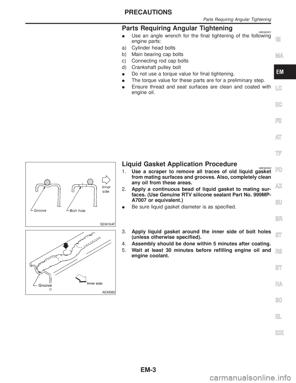
Parts Requiring Angular TighteningNBEM0001IUse an angle wrench for the final tightening of the following
engine parts:
a) Cylinder head bolts
b) Main bearing cap bolts
c) Connecting rod cap bolts
d) Crankshaft pulley bolt
IDo not use a torque value for final tightening.
IThe torque value for these parts are for a preliminary step.
IEnsure thread and seat surfaces are clean and coated with
engine oil.
SEM164F
Liquid Gasket Application ProcedureNBEM00021.Use a scraper to remove all traces of old liquid gasket
from mating surfaces and grooves. Also, completely clean
any oil from these areas.
2.Apply a continuous bead of liquid gasket to mating sur-
faces. (Use Genuine RTV silicone sealant Part No. 999MP-
A7007 or equivalent.)
IBe sure liquid gasket diameter is as specified.
AEM080
3.Apply liquid gasket around the inner side of bolt holes
(unless otherwise specified).
4.Assembly should be done within 5 minutes after coating.
5.Wait at least 30 minutes before refilling engine oil and
engine coolant.
GI
MA
LC
EC
FE
AT
TF
PD
AX
SU
BR
ST
RS
BT
HA
SC
EL
IDX
PRECAUTIONS
Parts Requiring Angular Tightening
EM-3
Page 1655 of 2395

SEM950F
TIGHTENING PROCEDURESNBEM0006S01Intake ManifoldNBEM0006S0101ITighten in numerical order shown in the figure.
1. Tighten all bolts and nuts to 5 to 10 N´m (0.5 to 1.0 kg-m, 44
to 86 in-lb).
2. Finally tighten all bolts and nuts to 26 to 31 N´m (2.7 to 3.2
kg-m, 20 to 23 ft-lb).
ITighten all bolts and nuts to the final torque, evenly dividing the
tightening into at least five steps.
SEM473G
Fuel TubeNBEM0006S0102ITighten in numerical order shown in the figure.
1. Tighten all bolts to 9.3 to 10.8 N´m (0.95 to 1.1 kg-m, 83 to 95
in-lb).
2. Then tighten all bolts to 21 to 26 N´m (2.1 to 2.7 kg-m, 15 to
20 ft-lb).
SEM474G
Fuel Pressure RegulatorNBEM0006S0103Tighten fuel pressure regulator to 2.9 to 3.8 N´m (0.3 to 0.39 kg-m,
26.0 to 33.9 in-lb).
ITighten screws evenly several times to have the fuel pres-
sure regulator tightened at the specified torque.
IAlways replace O-ring with new ones.
ILubricate O-ring with new engine oil.
SEM475G
Throttle BodyNBEM0006S0105ITighten in numerical order shown in the figure.
1. Tighten all bolts to 8.8 to 10.8 N´m (0.9 to 1.1 kg-m, 79 to 95
in-lb).
2. Then tighten all bolts to 18 to 21 N´m (1.8 to 2.2 kg-m, 13 to
15 ft-lb).
SEM476G
Upper Intake Manifold CollectorNBEM0006S0107Tighten bolts and nuts to 18 to 21 N´m (1.8 to 2.2 kg-m, 13 to 15
ft-lb) in numerical order shown in the figure.
OUTER COMPONENT PARTS
Removal and Installation (Cont'd)
EM-12
Page 1662 of 2395
SEM159F
4. Apply a continuous bead of liquid gasket to mating surface of
aluminum oil pan.
IUse Genuine RTV silicone sealant Part No. 999MP-A7007
or equivalent.
SEM467G
5. Apply liquid gasket to inner sealing surface as shown in figure.
IBe sure liquid gasket is 4.0 to 5.0 mm (0.157 to 0.197 in)
or 4.5 to 5.5 mm (0.177 to 0.217 in) wide.
IAttaching should be done within 5 minutes after coating.
SEM464G
6. Install O-rings, cylinder block and oil pump body.
SEM468G
7. Install aluminum oil pan.
ITighten bolts in numerical order.
IWait at least 30 minutes before refilling engine oil.
SEM469G
8. Install the four engine-to-transmission bolts. For tightening
torque, refer to AT-278, ªInstallationº.
9. Reinstall in the revrse order of removal.
GI
MA
LC
EC
FE
AT
TF
PD
AX
SU
BR
ST
RS
BT
HA
SC
EL
IDX
OIL PAN
Installation (Cont'd)
EM-19
Page 1675 of 2395
SEM435G
12. Install O-rings on rear timing chain case.
13. Apply liquid gasket to front timing chain case.
IRefer to ªPOSITION FOR APPLYING LIQUID GASKETº,
EM-21.
IBefore installation, wipe off the protruding sealant.
SEM436G
14. Install rear case pin into dowel pin hole on front timing chain
case.
15. Tighten bolts to the specified torque in order shown in the fig-
ure.
ILeave the bolts unattended for 30 minutes or more after
tightening.
SEM437G
16. Install CVTC cover.
a. Install O-rings at front timing chain case.
b. Install seal ring at CVTC covers.
c. Apply liquid gasket to CVTC covers.
Use genuine RTV silicone sealant Part No. 999MP-A7007 or
equivalent.
IBeing careful not to move the seal ring from the installation
groove, align the dowel pins on the chain case with the holes
to install the CVTC cover.
SEM438G
ITighten in numerical order as shown in the figure.
TIMING CHAIN
Installation (Cont'd)
EM-32
Page 1685 of 2395

SEM861E
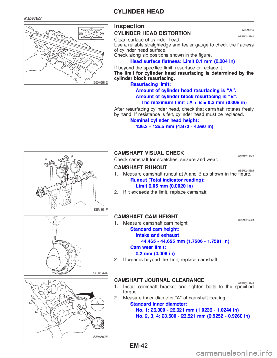
InspectionNBEM0019CYLINDER HEAD DISTORTIONNBEM0019S01Clean surface of cylinder head.
Use a reliable straightedge and feeler gauge to check the flatness
of cylinder head surface.
Check along six positions shown in the figure.
Head surface flatness: Limit 0.1 mm (0.004 in)
If beyond the specified limit, resurface or replace it.
The limit for cylinder head resurfacing is determined by the
cylinder block resurfacing.
Resurfacing limit:
Amount of cylinder head resurfacing is ªAº.
Amount of cylinder block resurfacing is ªBº.
The maximum limit : A+ B = 0.2 mm (0.008 in)
After resurfacing cylinder head, check that camshaft rotates freely
by hand. If resistance is felt, cylinder head must be replaced.
Nominal cylinder head height:
126.3 - 126.5 mm (4.972 - 4.980 in)
SEM191F
CAMSHAFT VISUAL CHECKNBEM0019S02Check camshaft for scratches, seizure and wear.
CAMSHAFT RUNOUTNBEM0019S031. Measure camshaft runout at A and B as shown in the figure.
Runout (Total indicator reading):
Limit 0.05 mm (0.0020 in)
2. If it exceeds the limit, replace camshaft.
SEM549A
CAMSHAFT CAM HEIGHTNBEM0019S041. Measure camshaft cam height.
Standard cam height:
Intake and exhaust
44.465 - 44.655 mm (1.7506 - 1.7581 in)
Cam wear limit:
0.2 mm (0.008 in)
2. If wear is beyond the limit, replace camshaft.
SEM862E
CAMSHAFT JOURNAL CLEARANCENBEM0019S051. Install camshaft bracket and tighten bolts to the specified
torque.
2. Measure inner diameter ªAº of camshaft bearing.
Standard inner diameter:
No. 1: 26.000 - 26.021 mm (1.0236 - 1.0244 in)
No. 2, 3, 4: 23.500 - 23.521 mm (0.9252 - 0.9260 in)
CYLINDER HEAD
Inspection
EM-42
Page 1694 of 2395
SEM885EA
SEM886EA
ITighten the camshaft brackets in the following steps.
Step Tightening torque Tightening order
1 1.96 N´m (0.2 kg-m, 17 in-lb)Tighten in the order of 7 to 10,
then tighten 1 to 6.
2 5.88 N´m (0.6 kg-m, 52 in-lb) Tighten in the numerical order.
39.02 - 11.8 N´m (0.92 - 1.20 kg-m,
79.9 - 104.2 in-lb)Tighten in the numerical order.
SEM443G
9. Install CVTC valves.
SEM534G
10. Install O-rings to cylinder block.
SEM447G
11. Install O-rings to cylinder head.
GI
MA
LC
EC
FE
AT
TF
PD
AX
SU
BR
ST
RS
BT
HA
SC
EL
IDX
CYLINDER HEAD
Installation (Cont'd)
EM-51
Page 1709 of 2395

SEM843E
SEM321AA
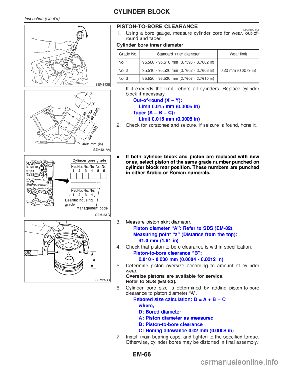
PISTON-TO-BORE CLEARANCENBEM0027S061. Using a bore gauge, measure cylinder bore for wear, out-of-
round and taper.
Cylinder bore inner diameter
Grade No. Standard inner diameter Wear limit
No. 1 95.500 - 95.510 mm (3.7598 - 3.7602 in)
0.20 mm (0.0079 in) No. 2 95.510 - 95.520 mm (3.7602 - 3.7606 in)
No. 3 95.520 - 95.530 mm (3.7606 - 3.7610 in)
If it exceeds the limit, rebore all cylinders. Replace cylinder
block if necessary.
Out-of-round (X þ Y):
Limit 0.015 mm (0.0006 in)
Taper (AþBþC):
Limit 0.015 mm (0.0006 in)
2. Check for scratches and seizure. If seizure is found, hone it.
SEM451G
IIf both cylinder block and piston are replaced with new
ones, select piston of the same grade number punched on
cylinder block rear position. These numbers are punched
in either Arabic or Roman numerals.
SEM258C
3. Measure piston skirt diameter.
Piston diameter ªAº: Refer to SDS (EM-82).
Measuring point ªaº (Distance from the top):
41.0 mm (1.61 in)
4. Check that piston-to-bore clearance is within specification.
Piston-to-bore clearance ªBº:
0.010 - 0.030 mm (0.0004 - 0.0012 in)
5. Determine piston oversize according to amount of cylinder
wear.
Oversize pistons are available for service.
Refer to SDS (EM-82).
6. Cylinder bore size is determined by adding piston-to-bore
clearance to piston diameter ªAº.
Rebored size calculation: D = A+BþC
where,
D: Bored diameter
A: Piston diameter as measured
B: Piston-to-bore clearance
C: Honing allowance 0.02 mm (0.0008 in)
7. Install main bearing caps, and tighten to the specified torque.
Otherwise, cylinder bores may be distorted in final assembly.
CYLINDER BLOCK
Inspection (Cont'd)
EM-66