Page 1497 of 2395
SECURITY INDICATOR LAMP CHECK=NBEL0123S05
1 CHECK INDICATOR LAMP OUTPUT SIGNAL
1. Disconnect smart entrance control unit connector.
2. Check voltage between control unit terminal 31 and ground.
SEL341X
Refer to wiring diagram in EL-300.
OK or NG
OK©Security indicator lamp is OK.
NG©GO TO 2.
2 CHECK INDICATOR LAMP
OK or NG
OK©GO TO 3.
NG©Replace indicator lamp.
3 CHECK POWER SUPPLY CIRCUIT FOR INDICATOR LAMP
1. Disconnect security lamp connector.
2. Check voltage between indicator lamp terminal 1 and ground.
SEL342X
OK or NG
OK©Check harness for open or short between security indicator lamp and control unit.
NG©Check the following.
I7.5A fuse [No. 24, located in fuse block (J/B)]
IHarness for open or short between security indicator lamp and fuse
THEFT WARNING SYSTEM
Trouble Diagnoses (Cont'd)
EL-312
Page 1504 of 2395

DescriptionNBEL0124The following systems are controlled by the smart entrance control unit.
IWarning chime
IRear window defogger and door mirror defogger timer
IPower door lock
IMulti-remote control system
ITheft warning system
IInterior lamp timer
IElectric sunroof and power window timer
IHeadlamp battery saver
IBattery saver
For detailed description and wiring diagrams, refer to the relevant pages for the each system.
The smart entrance control unit receives data from the switches and sensors to control their corresponding
system relays and actuators.
INPUT/OUTPUTNBEL0124S01
System Input Output
Power door lockDoor lock and unlock switch LH and RH
Key switch (Insert)
Door switches
Door key cylinder switchesDoor lock actuator
Multi-remote controlKey switch (Insert)
Ignition switch (ACC)
Door switches
Front door unlock sensor LH
Door lock and unlock switch LH
Remote controller signalHorn relay
Headlamp relay (LH and RH)
Interior lamp
Multi-remote control relay
Door lock actuator
Warning chimeKey switch (Insert)
Ignition switch (ON)
Lighting switch (1st)
Seat belt switch
Front door switch LHWarning chime (located in smart entrance
control unit)
Rear window defogger and
door mirror defogger timerIgnition switch (ON)
Rear window defogger switchRear window defogger relay
Theft warningIgnition switch (ACC, ON)
Door switches
Hood switch
Glass hatch switch
Door key cylinder switches (lock/unlock)
Door unlock sensoresHorn relay
Headlamp relay (LH and RH)
Security indicator
Interior lamp timerDoor switches
Front door unlock sensor LH
Ignition switch (ON)
Key switch (Insert)Interior lamp
Electric sunroof and power
window timerFront door switches
Ignition switch (ON)Power window relay
Headlamp battery saver timerFront door switches
Ignition switch (ON)Headlamp battery saver control unit
Battery saverIgnition switch (ON)
Door switches
Driver's door unlock sensor
Key switch (Insert)Interior lamp
Luggage room lamp
Spot lamp
Vanity mirror illumination lamp
GI
MA
EM
LC
EC
FE
AT
TF
PD
AX
SU
BR
ST
RS
BT
HA
SC
IDX
SMART ENTRANCE CONTROL UNIT
Description
EL-319
Page 1514 of 2395

System Description=NBEL0171NATS (Nissan Anti-Theft System) has the following immobilizer functions:
ISince only IVIS (NATS) ignition keys, whose ID nos. have been registered into the ECM and IMMU of IVIS
(NATS), allow the engine to run, operation of a stolen vehicle without an IVIS (NATS) registered key is
prevented by IVIS (NATS).
That is to say, IVIS (NATS) will immobilise the engine if someone tries to start it without the registered key
of IVIS (NATS).
IAll of the originally supplied ignition key IDs (except for card plate key) have been IVIS (NATS) registered.
If requested by the vehicle owner, a maximum of five key IDs can be registered into the IVIS (NATS) com-
ponents.
IThe security indicator blinks when the ignition switch is in ªOFFº or ªACCº position. Therefore, IVIS (NATS)
warns outsiders that the vehicle is equipped with the anti-theft system.
IWhen IVIS (NATS) detects trouble, the security indicator lamp lights up while ignition key is in the ªONº
position.
IIVIS (NATS) trouble diagnoses, system initialization and additional registration of other IVIS (NATS) igni-
tion key IDs must be carried out using CONSULT-II hardware and CONSULT-II IVIS (NATS) software.
When IVIS (NATS) initialization has been completed, the ID of the inserted ignition key is automatically
IVIS (NATS) registered. Then, if necessary, additional registration of other IVIS (NATS) ignition key IDs
can be carried out.
Regarding the procedures of IVIS (NATS) initialization and IVIS (NATS) ignition key ID registration, refer
to CONSULT-II operation manual, IVIS/NVIS.
IWhen servicing a malfunction of the IVIS (NATS) (indicated by lighting up of Security Indicator
Lamp) or registering another IVIS (NATS) ignition key ID no., it is necessary to re-register original
key identification. Therefore, be sure to receive ALL KEYS from vehicle owner.
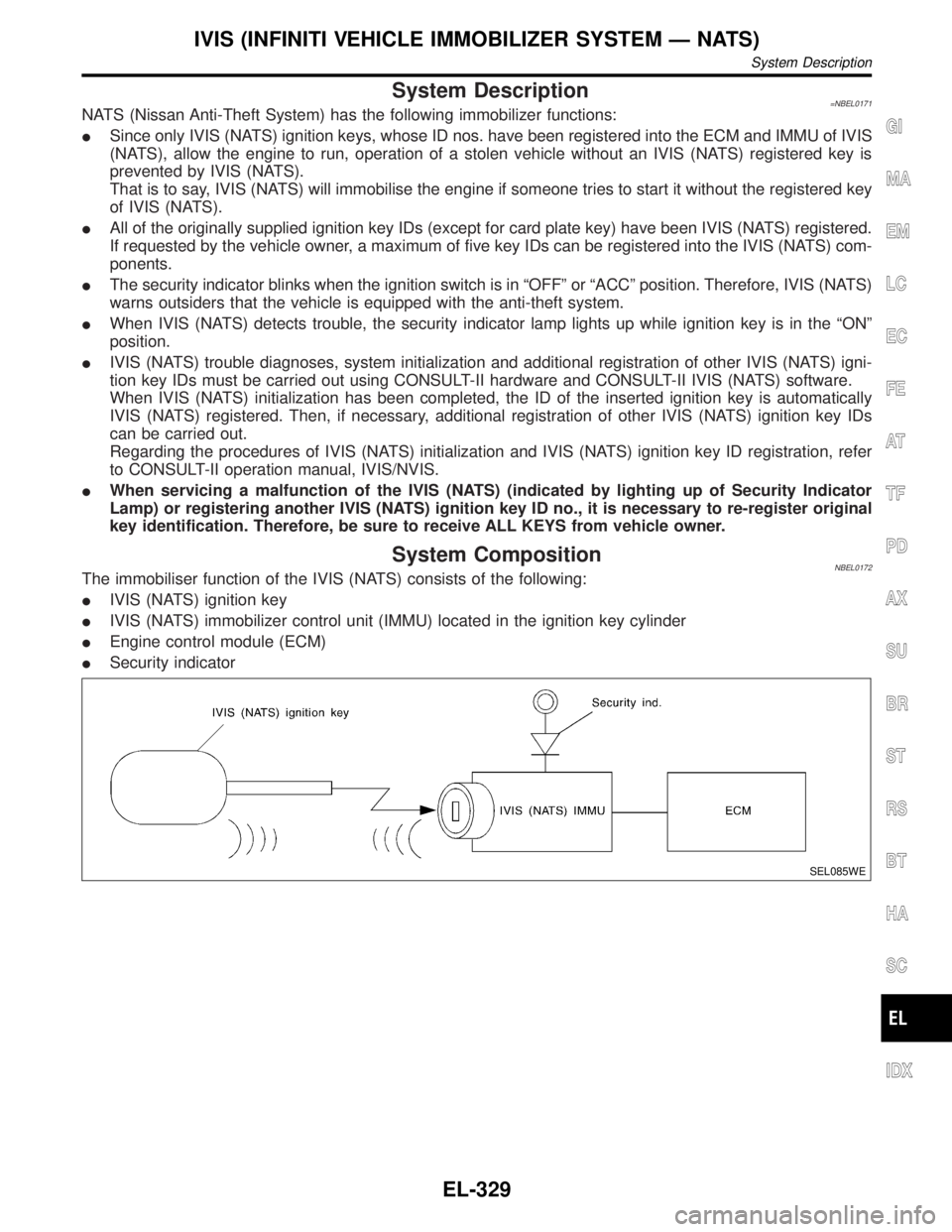
System CompositionNBEL0172The immobiliser function of the IVIS (NATS) consists of the following:
IIVIS (NATS) ignition key
IIVIS (NATS) immobilizer control unit (IMMU) located in the ignition key cylinder
IEngine control module (ECM)
ISecurity indicator
SEL085WE
GI
MA
EM
LC
EC
FE
AT
TF
PD
AX
SU
BR
ST
RS
BT
HA
SC
IDX
IVIS (INFINITI VEHICLE IMMOBILIZER SYSTEM Ð NATS)
System Description
EL-329
Page 1518 of 2395
Detected items (NATS program card
screen terms)P No. Code
(Self-diag-
nostic
result of
ªENGINEºMalfunction is detected when .....
Reference page
LOCK MODENATS MAL-
FUNCTION
P1610When the starting operation is carried out five or more
times consecutively under the following conditions, IVIS
(NATS) will shift the mode to one which prevents the
engine from being started.
IUnregistered ignition key is used.
IIMMU or ECM's malfunctioning.EL-346
DON'T ERASE BEFORE
CHECKING ENG DIAGÐAll engine trouble codes except IVIS (NATS) trouble
code has been detected in ECM.EL-334GI
MA
EM
LC
EC
FE
AT
TF
PD
AX
SU
BR
ST
RS
BT
HA
SC
IDX
IVIS (INFINITI VEHICLE IMMOBILIZER SYSTEM Ð NATS)
CONSULT-II (Cont'd)
EL-333
Page 1520 of 2395

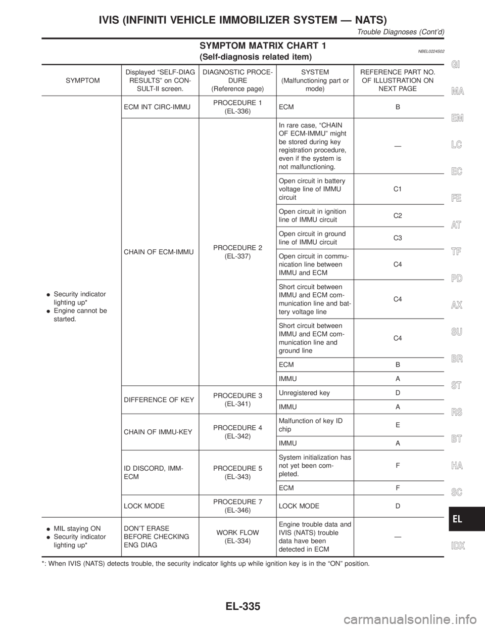
SYMPTOM MATRIX CHART 1NBEL0224S02(Self-diagnosis related item)
SYMPTOMDisplayed ªSELF-DIAG
RESULTSº on CON-
SULT-II screen.DIAGNOSTIC PROCE-
DURE
(Reference page)SYSTEM
(Malfunctioning part or
mode)REFERENCE PART NO.
OF ILLUSTRATION ON
NEXT PAGE
ISecurity indicator
lighting up*
IEngine cannot be
started.ECM INT CIRC-IMMUPROCEDURE 1
(EL-336)ECM B
CHAIN OF ECM-IMMUPROCEDURE 2
(EL-337)In rare case, ªCHAIN
OF ECM-IMMUº might
be stored during key
registration procedure,
even if the system is
not malfunctioning.Ð
Open circuit in battery
voltage line of IMMU
circuitC1
Open circuit in ignition
line of IMMU circuitC2
Open circuit in ground
line of IMMU circuitC3
Open circuit in commu-
nication line between
IMMU and ECMC4
Short circuit between
IMMU and ECM com-
munication line and bat-
tery voltage lineC4
Short circuit between
IMMU and ECM com-
munication line and
ground lineC4
ECM B
IMMU A
DIFFERENCE OF KEYPROCEDURE 3
(EL-341)Unregistered key D
IMMU A
CHAIN OF IMMU-KEYPROCEDURE 4
(EL-342)Malfunction of key ID
chipE
IMMU A
ID DISCORD, IMM-
ECMPROCEDURE 5
(EL-343)System initialization has
not yet been com-
pleted.F
ECM F
LOCK MODEPROCEDURE 7
(EL-346)LOCK MODE D
IMIL staying ON
ISecurity indicator
lighting up*DON'T ERASE
BEFORE CHECKING
ENG DIAGWORK FLOW
(EL-334)Engine trouble data and
IVIS (NATS) trouble
data have been
detected in ECMÐ
*: When IVIS (NATS) detects trouble, the security indicator lights up while ignition key is in the ªONº position.
GI
MA
EM
LC
EC
FE
AT
TF
PD
AX
SU
BR
ST
RS
BT
HA
SC
IDX
IVIS (INFINITI VEHICLE IMMOBILIZER SYSTEM Ð NATS)
Trouble Diagnoses (Cont'd)
EL-335
Page 1521 of 2395
SYMPTOM MATRIX CHART 2NBEL0224S03(Non self-diagnosis related item)
SYMPTOMDIAGNOSTIC PROCEDURE
(Reference page)SYSTEM
(Malfunctioning part or mode)
Security ind. does not light up.PROCEDURE 6
(EL-344)Security ind.
Open circuit between Fuse and IMMU
Continuation of initialization mode
IMMU
DIAGNOSTIC SYSTEM DIAGRAMNBEL0224S04
SEL087WD
SEL365X
DIAGNOSTIC PROCEDURE 1NBEL0224S05Self-diagnostic results:
ªECM INT CIRC-IMMUº displayed on CONSULT-II screen
1. Confirm SELF-DIAGNOSTIC RESULTS ªECM INT CIRC-
IMMUº displayed on CONSULT-II screen. Ref. part No. B.
2. Replace ECM.
3. Perform initialization with CONSULT-II.
For initialization, refer to ªCONSULT-II operation manual
IVIS/NVISº.
IVIS (INFINITI VEHICLE IMMOBILIZER SYSTEM Ð NATS)
Trouble Diagnoses (Cont'd)
EL-336
Page 1529 of 2395
![INFINITI QX4 2001 Factory Service Manual DIAGNOSTIC PROCEDURE 6=NBEL0224S10ªSECURITY INDICATOR LAMP DOES NOT LIGHT UPº
1 CHECK FUSE
Check 10A fuse [No. 12, located in the fuse block (J/B)].
Is 10A fuse OK?
Ye s©GO TO 2.
No©Replace fuse.
INFINITI QX4 2001 Factory Service Manual DIAGNOSTIC PROCEDURE 6=NBEL0224S10ªSECURITY INDICATOR LAMP DOES NOT LIGHT UPº
1 CHECK FUSE
Check 10A fuse [No. 12, located in the fuse block (J/B)].
Is 10A fuse OK?
Ye s©GO TO 2.
No©Replace fuse.](/manual-img/42/57027/w960_57027-1528.png)
DIAGNOSTIC PROCEDURE 6=NBEL0224S10ªSECURITY INDICATOR LAMP DOES NOT LIGHT UPº
1 CHECK FUSE
Check 10A fuse [No. 12, located in the fuse block (J/B)].
Is 10A fuse OK?
Ye s©GO TO 2.
No©Replace fuse.
2 CHECK SECURITY INDICATOR LAMP
1. Install 10A fuse.
2. Perform initialization with CONSULT-II.
For initialization, refer to ªCONSULT-II Operation Manual IVIS/NVISº.
3. Turn ignition switch OFF.
4. Start engine and turn ignition switch OFF.
5. Check the security indicator lamp lighting.
Security indicator lamp should be blinking.
OK or NG
OK©INSPECTION END
NG©GO TO 3.
3 CHECK SECURITY INDICATOR LAMP POWER SUPPLY CIRCUIT
1. Disconnect security indicator lamp connector.
2. Check voltage between security indicator lamp connector terminal 1 and ground.
SEL370X
OK or NG
OK©GO TO 4.
NG©Check harness for open or short between fuse and security indicator lamp.
4 CHECK SECURITY INDICATOR LAMP
Check security Indicator Lamp.
Is security indicator lamp OK?
Ye s©GO TO 5.
No©Replace security indicator lamp.
IVIS (INFINITI VEHICLE IMMOBILIZER SYSTEM Ð NATS)
Trouble Diagnoses (Cont'd)
EL-344
Page 1530 of 2395
5 CHECK IMMU FUNCTION
1. Connect IMMU connector.
2. Disconnect security indicator lamp connector.
3. Check continuity between IMMU terminal 5 and ground.
SEL300WC
OK or NG
OK©Check harness for open or short between security indicator lamp and IMMU.
NG©IMMU is malfunctioning.
Replace IMMU.
Perform initialization with CONSULT-II.
For initialization, refer to ªCONSULT-II operation manual IVIS/NVISº.
GI
MA
EM
LC
EC
FE
AT
TF
PD
AX
SU
BR
ST
RS
BT
HA
SC
IDX
IVIS (INFINITI VEHICLE IMMOBILIZER SYSTEM Ð NATS)
Trouble Diagnoses (Cont'd)
EL-345