Page 1820 of 2395

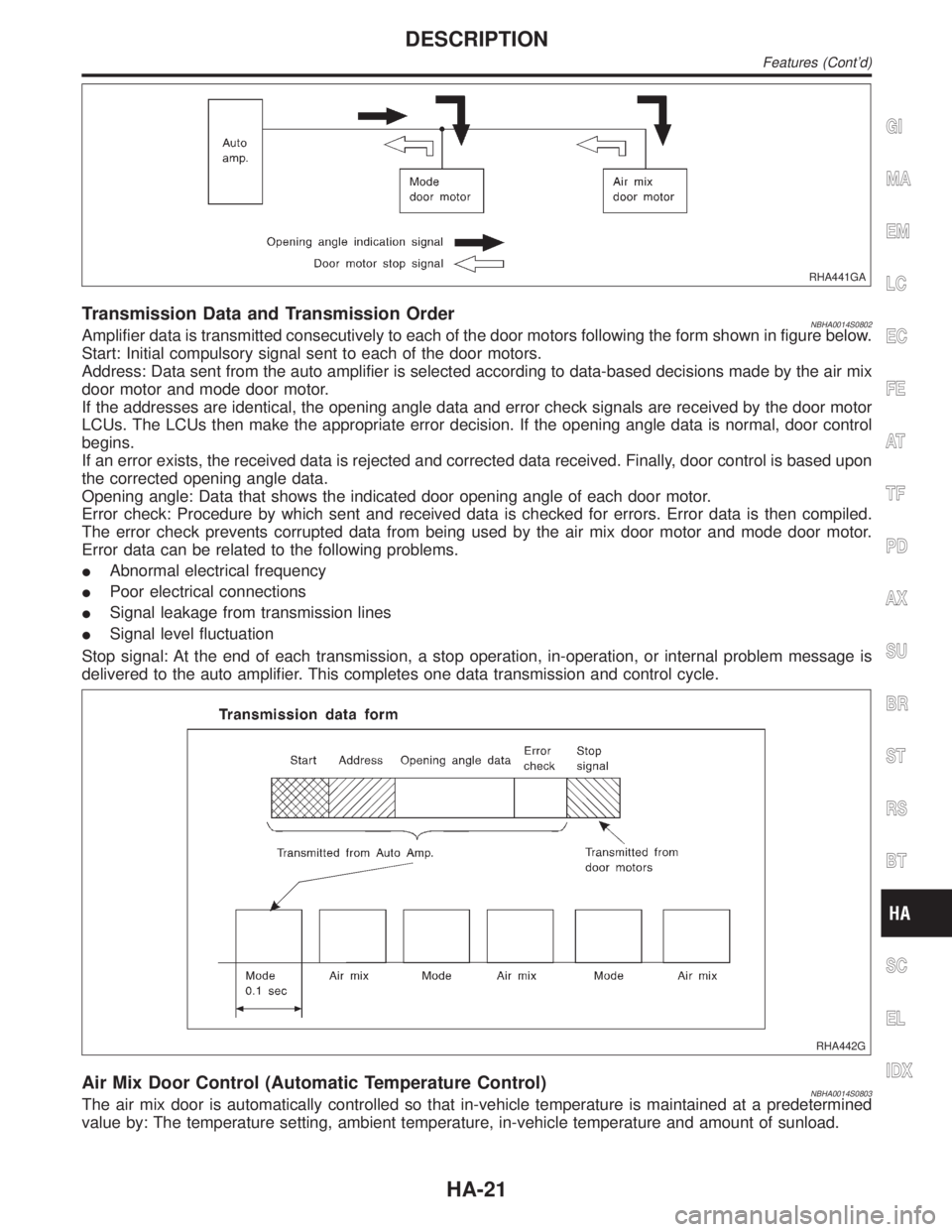
RHA441GA
Transmission Data and Transmission OrderNBHA0014S0802Amplifier data is transmitted consecutively to each of the door motors following the form shown in figure below.
Start: Initial compulsory signal sent to each of the door motors.
Address: Data sent from the auto amplifier is selected according to data-based decisions made by the air mix
door motor and mode door motor.
If the addresses are identical, the opening angle data and error check signals are received by the door motor
LCUs. The LCUs then make the appropriate error decision. If the opening angle data is normal, door control
begins.
If an error exists, the received data is rejected and corrected data received. Finally, door control is based upon
the corrected opening angle data.
Opening angle: Data that shows the indicated door opening angle of each door motor.
Error check: Procedure by which sent and received data is checked for errors. Error data is then compiled.
The error check prevents corrupted data from being used by the air mix door motor and mode door motor.
Error data can be related to the following problems.
IAbnormal electrical frequency
IPoor electrical connections
ISignal leakage from transmission lines
ISignal level fluctuation
Stop signal: At the end of each transmission, a stop operation, in-operation, or internal problem message is
delivered to the auto amplifier. This completes one data transmission and control cycle.
RHA442G
Air Mix Door Control (Automatic Temperature Control)NBHA0014S0803The air mix door is automatically controlled so that in-vehicle temperature is maintained at a predetermined
value by: The temperature setting, ambient temperature, in-vehicle temperature and amount of sunload.
GI
MA
EM
LC
EC
FE
AT
TF
PD
AX
SU
BR
ST
RS
BT
SC
EL
IDX
DESCRIPTION
Features (Cont'd)
HA-21
Page 1822 of 2395
Overview of Control System=NBHA0015The control system consists of input sensors, switches, the automatic amplifier (microcomputer) and outputs.
The relationship of these components is shown in the diagram below:
RHA856H
Control OperationNBHA0016
RHA452GA
GI
MA
EM
LC
EC
FE
AT
TF
PD
AX
SU
BR
ST
RS
BT
SC
EL
IDX
DESCRIPTION
Overview of Control System
HA-23
Page 1824 of 2395
Discharge Air FlowNBHA0017
RHA043G
GI
MA
EM
LC
EC
FE
AT
TF
PD
AX
SU
BR
ST
RS
BT
SC
EL
IDX
DESCRIPTION
Discharge Air Flow
HA-25
Page 1826 of 2395
Component LocationNBHA0033ENGINE COMPARTMENTNBHA0033S01
SHA281FA
GI
MA
EM
LC
EC
FE
AT
TF
PD
AX
SU
BR
ST
RS
BT
SC
EL
IDX
TROUBLE DIAGNOSES
Component Location
HA-27
Page 1828 of 2395
With Navigation SystemNBHA0033S0202
RHA857H
GI
MA
EM
LC
EC
FE
AT
TF
PD
AX
SU
BR
ST
RS
BT
SC
EL
IDX
TROUBLE DIAGNOSES
Component Location (Cont'd)
HA-29
Page 1830 of 2395
Wiring Diagram Ð A/C, A Ð (Without
Navigation System)
NBHA0035
MHA974A
GI
MA
EM
LC
EC
FE
AT
TF
PD
AX
SU
BR
ST
RS
BT
SC
EL
IDX
TROUBLE DIAGNOSES
Wiring Diagram Ð A/C, A Ð (Without Navigation System)
HA-31
Page 1832 of 2395
MHA976A
GI
MA
EM
LC
EC
FE
AT
TF
PD
AX
SU
BR
ST
RS
BT
SC
EL
IDX
TROUBLE DIAGNOSES
Wiring Diagram Ð A/C, A Ð (Without Navigation System) (Cont'd)
HA-33
Page 1834 of 2395
Circuit Diagram (With Navigation System)NBHA0113
MHA978A
GI
MA
EM
LC
EC
FE
AT
TF
PD
AX
SU
BR
ST
RS
BT
SC
EL
IDX
TROUBLE DIAGNOSES
Circuit Diagram (With Navigation System)
HA-35