Page 1804 of 2395
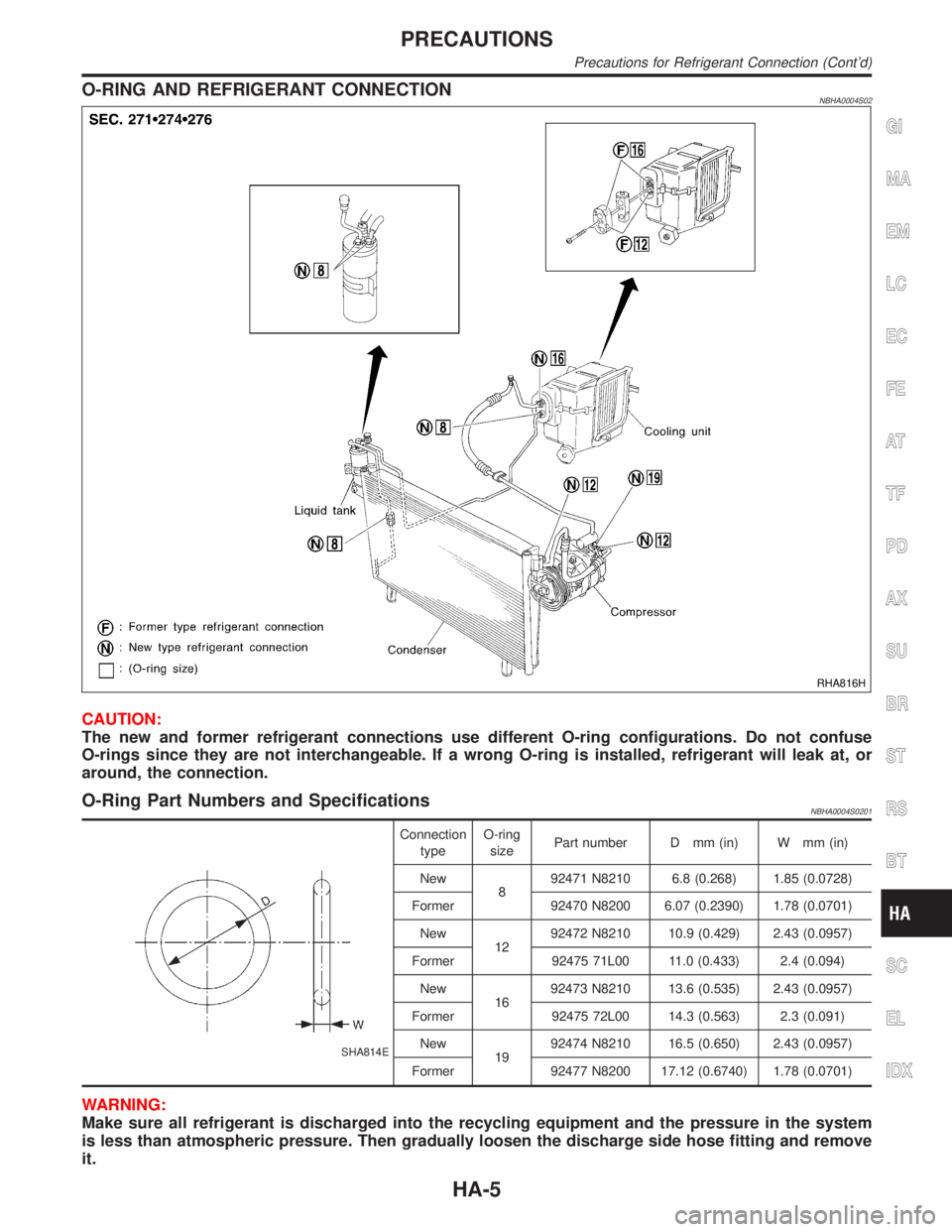
O-RING AND REFRIGERANT CONNECTIONNBHA0004S02
RHA816H
CAUTION:
The new and former refrigerant connections use different O-ring configurations. Do not confuse
O-rings since they are not interchangeable. If a wrong O-ring is installed, refrigerant will leak at, or
around, the connection.
O-Ring Part Numbers and SpecificationsNBHA0004S0201
SHA814E
Connection
typeO-ring
sizePart number D mm (in) W mm (in)
New
892471 N8210 6.8 (0.268) 1.85 (0.0728)
Former 92470 N8200 6.07 (0.2390) 1.78 (0.0701)
New
1292472 N8210 10.9 (0.429) 2.43 (0.0957)
Former 92475 71L00 11.0 (0.433) 2.4 (0.094)
New
1692473 N8210 13.6 (0.535) 2.43 (0.0957)
Former 92475 72L00 14.3 (0.563) 2.3 (0.091)
New
1992474 N8210 16.5 (0.650) 2.43 (0.0957)
Former 92477 N8200 17.12 (0.6740) 1.78 (0.0701)
WARNING:
Make sure all refrigerant is discharged into the recycling equipment and the pressure in the system
is less than atmospheric pressure. Then gradually loosen the discharge side hose fitting and remove
it.
GI
MA
EM
LC
EC
FE
AT
TF
PD
AX
SU
BR
ST
RS
BT
SC
EL
IDX
PRECAUTIONS
Precautions for Refrigerant Connection (Cont'd)
HA-5
Page 1806 of 2395
Precautions for Service EquipmentNBHA0006RECOVERY/RECYCLING EQUIPMENTNBHA0006S01Be certain to follow the manufacturers instructions for machine
operation and machine maintenance. Never introduce any refriger-
ant other than that specified into the machine.
ELECTRONIC LEAK DETECTORNBHA0006S02Be certain to follow the manufacturer's instructions for tester opera-
tion and tester maintenance.
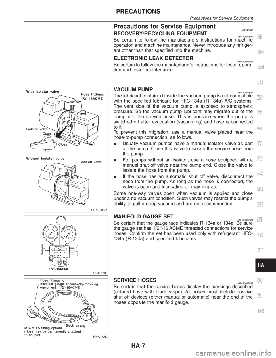
RHA270DA
VACUUM PUMPNBHA0006S03The lubricant contained inside the vacuum pump is not compatible
with the specified lubricant for HFC-134a (R-134a) A/C systems.
The vent side of the vacuum pump is exposed to atmospheric
pressure. So the vacuum pump lubricant may migrate out of the
pump into the service hose. This is possible when the pump is
switched off after evacuation (vacuuming) and hose is connected
to it.
To prevent this migration, use a manual valve placed near the
hose-to-pump connection, as follows.
IUsually vacuum pumps have a manual isolator valve as part
of the pump. Close this valve to isolate the service hose from
the pump.
IFor pumps without an isolator, use a hose equipped with a
manual shut-off valve near the pump end. Close the valve to
isolate the hose from the pump.
IIf the hose has an automatic shut off valve, disconnect the
hose from the pump. As long as the hose is connected, the
valve is open and lubricating oil may migrate.
Some one-way valves open when vacuum is applied and close
under a no vacuum condition. Such valves may restrict the pump's
ability to pull a deep vacuum and are not recommended.
SHA533D
MANIFOLD GAUGE SETNBHA0006S04Be certain that the gauge face indicates R-134a or 134a. Be sure
the gauge set has 1/2²-16 ACME threaded connections for service
hoses. Confirm the set has been used only with refrigerant HFC-
134a (R-134a) and specified lubricants.
RHA272D
SERVICE HOSESNBHA0006S05Be certain that the service hoses display the markings described
(colored hose with black stripe). All hoses must include positive
shut off devices (either manual or automatic) near the end of the
hoses opposite the manifold gauge.
GI
MA
EM
LC
EC
FE
AT
TF
PD
AX
SU
BR
ST
RS
BT
SC
EL
IDX
PRECAUTIONS
Precautions for Service Equipment
HA-7
Page 1808 of 2395
Wiring Diagrams and Trouble DiagnosesNBHA0007When you read wiring diagrams, refer to the following:
IGI-11, ªHOW TO READ WIRING DIAGRAMSº
IEL-10, ªWiring Diagram Ð POWER к for power distribution
circuit
When you perform trouble diagnoses, refer to the following:
IGI-34, ªHOW TO FOLLOW TROUBLE DIAGNOSESº
IGI-24, ªHOW TO PERFORM EFFICIENT DIAGNOSIS FOR
AN ELECTRICAL INCIDENTºGI
MA
EM
LC
EC
FE
AT
TF
PD
AX
SU
BR
ST
RS
BT
SC
EL
IDX
PRECAUTIONS
Wiring Diagrams and Trouble Diagnoses
HA-9
Page 1810 of 2395
HFC-134a (R-134a) Service Tools and
Equipment
=NBHA0009Never mix HFC-134a refrigerant and/or its specified lubricant with CFC-12 (R-12) refrigerant and/or its lubri-
cant.
Separate and non-interchangeable service equipment must be used for handling each type of refrigerant/
lubricant.
Refrigerant container fittings, service hose fittings and service equipment fittings (equipment which handles
refrigerant and/or lubricant) are different between CFC-12 (R-12) and HFC-134a (R-134a). This is to avoid
mixed use of the refrigerants/lubricant.
Adapters that convert one size fitting to another must never be used: refrigerant/lubricant contamination will
occur and compressor failure will result.
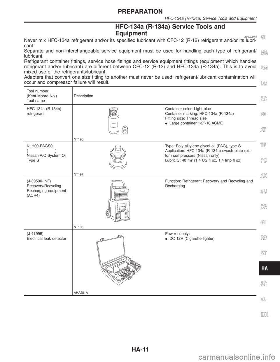
Tool number
(Kent-Moore No.)
Tool nameDescription
HFC-134a (R-134a)
refrigerant
NT196
Container color: Light blue
Container marking: HFC-134a (R-134a)
Fitting size: Thread size
ILarge container 1/2²-16 ACME
KLH00-PAGS0
(Ð)
Nissan A/C System Oil
Type S
NT197
Type: Poly alkylene glycol oil (PAG), type S
Application: HFC-134a (R-134a) swash plate (pis-
ton) compressors (Nissan only)
Lubricity: 40 m(1.4 US fl oz, 1.4 Imp fl oz)
(J-39500-INF)
Recovery/Recycling
Recharging equipment
(ACR4)
NT195
Function: Refrigerant Recovery and Recycling and
Recharging
(J-41995)
Electrical leak detector
AHA281A
Power supply:
IDC 12V (Cigarette lighter)
GI
MA
EM
LC
EC
FE
AT
TF
PD
AX
SU
BR
ST
RS
BT
SC
EL
IDX
PREPARATION
HFC-134a (R-134a) Service Tools and Equipment
HA-11
Page 1812 of 2395
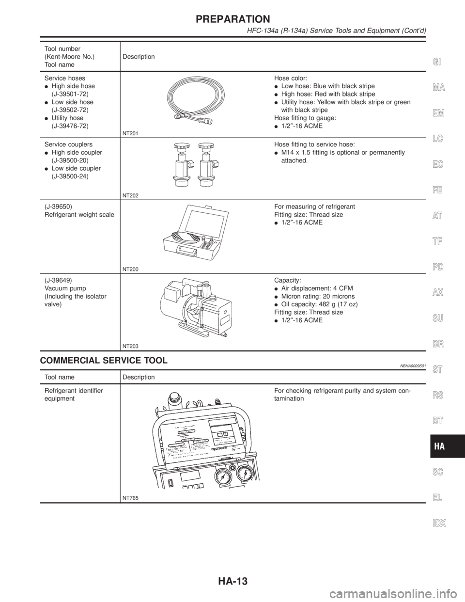
Tool number
(Kent-Moore No.)
Tool nameDescription
Service hoses
IHigh side hose
(J-39501-72)
ILow side hose
(J-39502-72)
IUtility hose
(J-39476-72)
NT201
Hose color:
ILow hose: Blue with black stripe
IHigh hose: Red with black stripe
IUtility hose: Yellow with black stripe or green
with black stripe
Hose fitting to gauge:
I1/2²-16 ACME
Service couplers
IHigh side coupler
(J-39500-20)
ILow side coupler
(J-39500-24)
NT202
Hose fitting to service hose:
IM14 x 1.5 fitting is optional or permanently
attached.
(J-39650)
Refrigerant weight scale
NT200
For measuring of refrigerant
Fitting size: Thread size
I1/2²-16 ACME
(J-39649)
Vacuum pump
(Including the isolator
valve)
NT203
Capacity:
IAir displacement: 4 CFM
IMicron rating: 20 microns
IOil capacity: 482 g (17 oz)
Fitting size: Thread size
I1/2²-16 ACME
COMMERCIAL SERVICE TOOLNBHA0009S01
Tool name Description
Refrigerant identifier
equipment
NT765
For checking refrigerant purity and system con-
tamination
GI
MA
EM
LC
EC
FE
AT
TF
PD
AX
SU
BR
ST
RS
BT
SC
EL
IDX
PREPARATION
HFC-134a (R-134a) Service Tools and Equipment (Cont'd)
HA-13
Page 1814 of 2395
V-6 Variable Displacement Compressor
GENERAL INFORMATION=NBHA00861. The V-6 variable compressor differs from previous units. The vent temperatures of the V-6 variable com-
press do not drop too far below 5ÉC (41ÉF) when:
Ievaporator intake air temperature is less than 20ÉC (68ÉF)
Iengine is running at speeds less than 1,500 rpm.
This is because the V-6 compressor provides a means of ªcapacityº control.
2. The V-6 variable compressor provides refrigerant control under varying conditions. During cold winters, it
may not produce high refrigerant pressure discharge (compared to previous units) when used with air
conditioning systems.
3. A ªclankingº sound may occasionally be heard during refrigerant charge. The sound indicates that the tilt
angle of the swash plate has changed and is not a problem.
4. For air conditioning systems with the V-6 compressor, the clutch remains engaged unless: the system main
switch, fan switch or ignition switch is turned OFF. When ambient (outside) temperatures are low or when
the amount of refrigerant is insufficient, the clutch is disengaged to protect the compressor.
5. A constant range of suction pressure is maintained when engine speed is greater than a certain value. It
normally ranges from 147 to 177 kPa (1.5 to 1.8 kg/cm
2, 21 to 26 psi) under varying conditions.
In previous compressors, however, suction pressure was reduced with increases in engine speed.
GI
MA
EM
LC
EC
FE
AT
TF
PD
AX
SU
BR
ST
RS
BT
SC
EL
IDX
DESCRIPTION
V-6 Variable Displacement Compressor
HA-15
Page 1816 of 2395
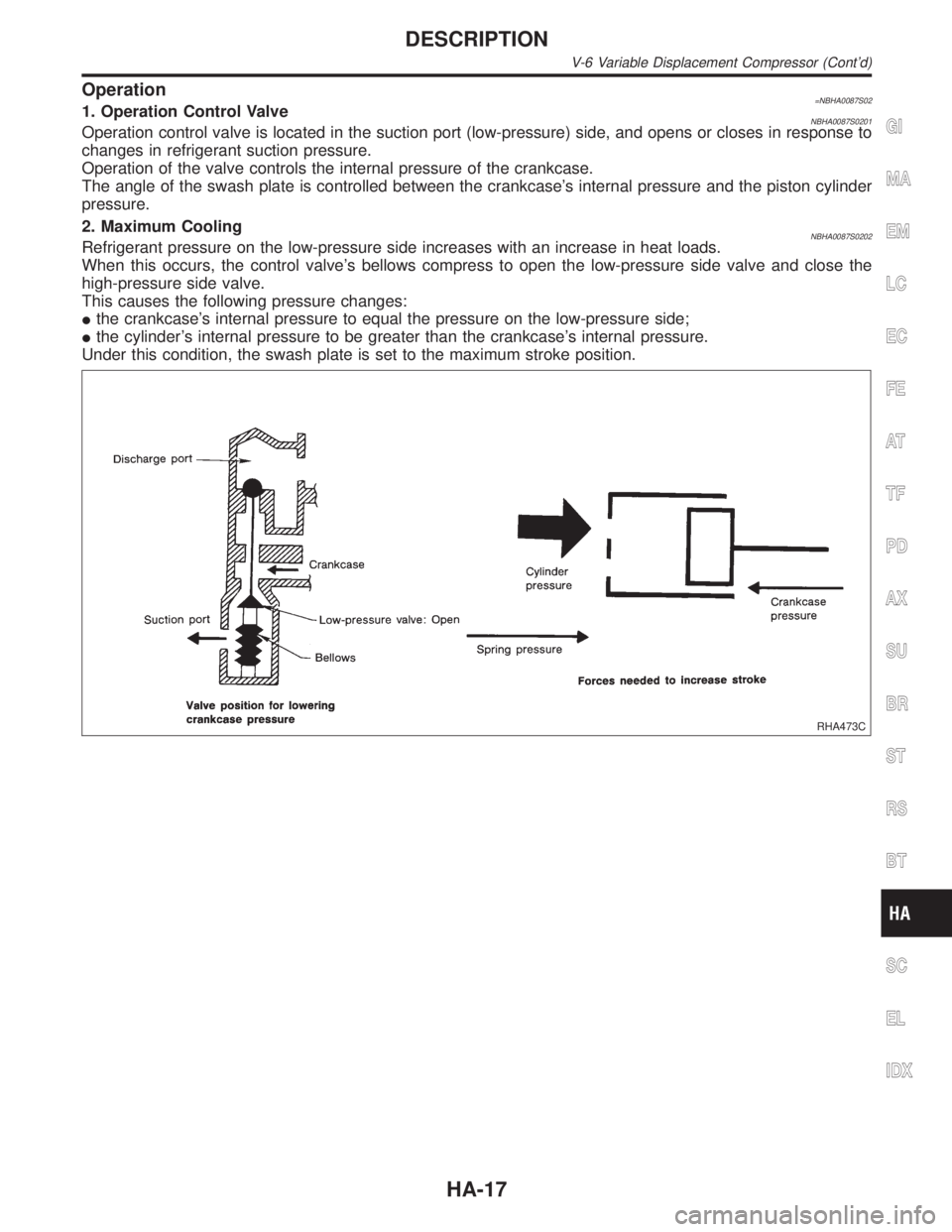
Operation=NBHA0087S021. Operation Control ValveNBHA0087S0201Operation control valve is located in the suction port (low-pressure) side, and opens or closes in response to
changes in refrigerant suction pressure.
Operation of the valve controls the internal pressure of the crankcase.
The angle of the swash plate is controlled between the crankcase's internal pressure and the piston cylinder
pressure.
2. Maximum Cooling
NBHA0087S0202Refrigerant pressure on the low-pressure side increases with an increase in heat loads.
When this occurs, the control valve's bellows compress to open the low-pressure side valve and close the
high-pressure side valve.
This causes the following pressure changes:
Ithe crankcase's internal pressure to equal the pressure on the low-pressure side;
Ithe cylinder's internal pressure to be greater than the crankcase's internal pressure.
Under this condition, the swash plate is set to the maximum stroke position.
RHA473C
GI
MA
EM
LC
EC
FE
AT
TF
PD
AX
SU
BR
ST
RS
BT
SC
EL
IDX
DESCRIPTION
V-6 Variable Displacement Compressor (Cont'd)
HA-17
Page 1818 of 2395
Component LayoutNBHA0012
RHA451G
GI
MA
EM
LC
EC
FE
AT
TF
PD
AX
SU
BR
ST
RS
BT
SC
EL
IDX
DESCRIPTION
Component Layout
HA-19