2001 DODGE TOWN AND COUNTRY back
[x] Cancel search: backPage 205 of 2321
must be replaced. (Refer to 2 - SUSPENSION/
FRONT/HUB / BEARING - REMOVAL).
If the hub runout does not exceed this specifica-
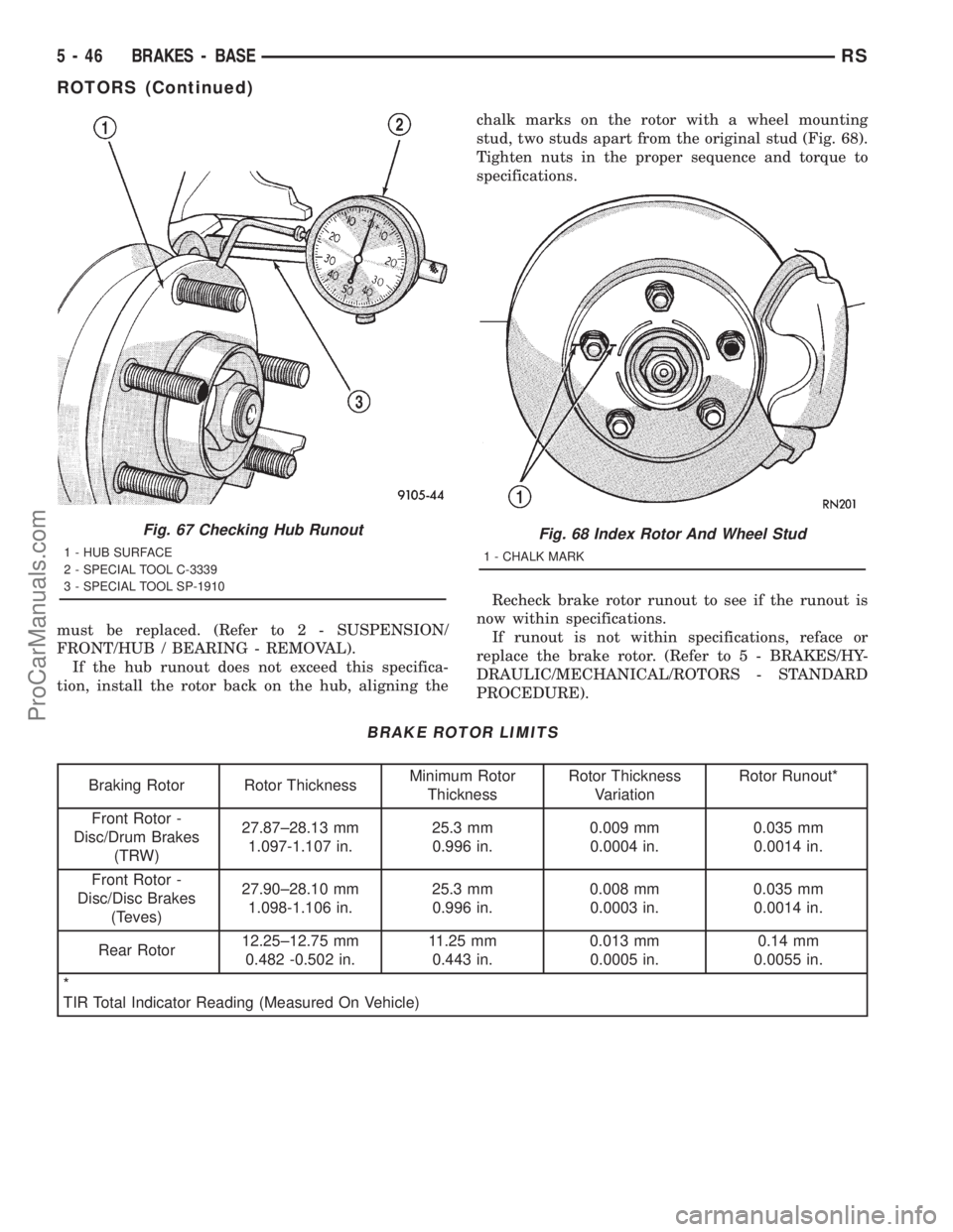
tion, install the rotor back on the hub, aligning thechalk marks on the rotor with a wheel mounting
stud, two studs apart from the original stud (Fig. 68).
Tighten nuts in the proper sequence and torque to
specifications.
Recheck brake rotor runout to see if the runout is
now within specifications.
If runout is not within specifications, reface or
replace the brake rotor. (Refer to 5 - BRAKES/HY-
DRAULIC/MECHANICAL/ROTORS - STANDARD
PROCEDURE).
BRAKE ROTOR LIMITS
Braking Rotor Rotor ThicknessMinimum Rotor
ThicknessRotor Thickness
VariationRotor Runout*
Front Rotor -
Disc/Drum Brakes
(TRW)27.87±28.13 mm
1.097-1.107 in.25.3 mm
0.996 in.0.009 mm
0.0004 in.0.035 mm
0.0014 in.
Front Rotor -
Disc/Disc Brakes
(Teves)27.90±28.10 mm
1.098-1.106 in.25.3 mm
0.996 in.0.008 mm
0.0003 in.0.035 mm
0.0014 in.
Rear Rotor12.25±12.75 mm
0.482 -0.502 in.11.25 mm
0.443 in.0.013 mm
0.0005 in.0.14 mm
0.0055 in.
*
TIR Total Indicator Reading (Measured On Vehicle)
Fig. 67 Checking Hub Runout
1 - HUB SURFACE
2 - SPECIAL TOOL C-3339
3 - SPECIAL TOOL SP-1910
Fig. 68 Index Rotor And Wheel Stud
1 - CHALK MARK
5 - 46 BRAKES - BASERS
ROTORS (Continued)
ProCarManuals.com
Page 207 of 2321
BRAKE ROTOR LIMITS
Braking RotorRotor
ThicknessMinimum
Rotor
ThicknessRotor
Thickness
VariationRotor
Runout*
Front Rotor -
Disc/Drum Brakes
(TRW)27.87±28.13
mm
1.097-1.107
in.25.3 mm
0.996 in.0.009 mm
0.0004 in.0.035 mm
0.0014 in.
Front Rotor -
Disc/Disc Brakes
(Teves)27.90±28.10
mm
1.098-1.106
in.25.3 mm
0.996 in.0.008 mm
0.0003 in.0.035 mm
0.0014 in.
Rear Rotor12.25±12.75
mm
0.482 -0.502
in.11.25 mm
0.443 in.0.013 mm
0.0005 in.0.14 mm
0.0055 in.
*
TIR Total Indicator Reading (Measured On Vehicle)
REMOVAL - FRONT BRAKE ROTOR
(1) Raise vehicle on jackstands or centered on a
frame contact type hoist. See Hoisting in Lubrication
and Maintenance.
(2) Remove the front wheel and tire assembly.
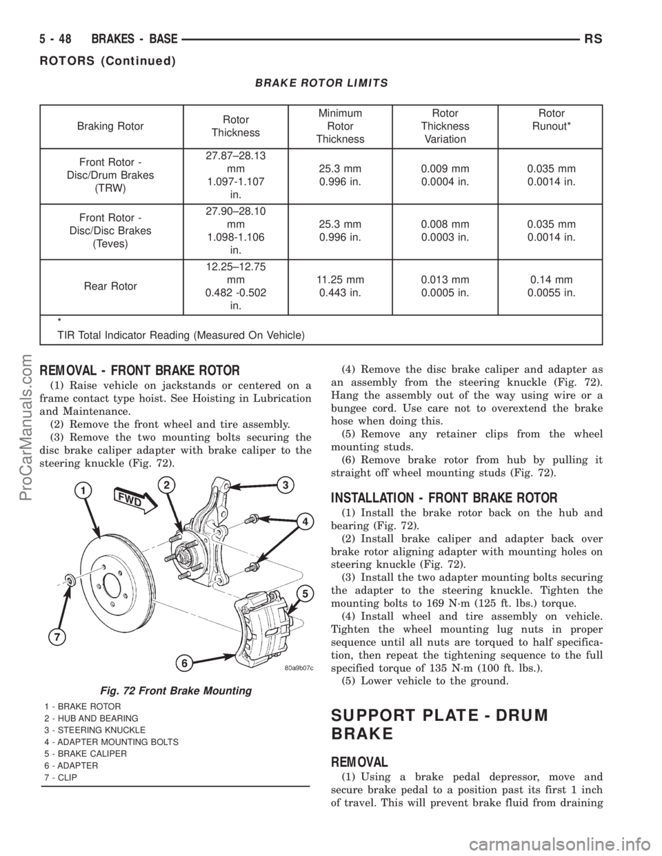
(3) Remove the two mounting bolts securing the
disc brake caliper adapter with brake caliper to the
steering knuckle (Fig. 72).(4) Remove the disc brake caliper and adapter as
an assembly from the steering knuckle (Fig. 72).
Hang the assembly out of the way using wire or a
bungee cord. Use care not to overextend the brake
hose when doing this.
(5) Remove any retainer clips from the wheel
mounting studs.
(6) Remove brake rotor from hub by pulling it
straight off wheel mounting studs (Fig. 72).
INSTALLATION - FRONT BRAKE ROTOR
(1) Install the brake rotor back on the hub and
bearing (Fig. 72).
(2) Install brake caliper and adapter back over
brake rotor aligning adapter with mounting holes on
steering knuckle (Fig. 72).
(3) Install the two adapter mounting bolts securing
the adapter to the steering knuckle. Tighten the
mounting bolts to 169 N´m (125 ft. lbs.) torque.
(4) Install wheel and tire assembly on vehicle.
Tighten the wheel mounting lug nuts in proper
sequence until all nuts are torqued to half specifica-
tion, then repeat the tightening sequence to the full
specified torque of 135 N´m (100 ft. lbs.).
(5) Lower vehicle to the ground.
SUPPORT PLATE - DRUM
BRAKE
REMOVAL
(1) Using a brake pedal depressor, move and
secure brake pedal to a position past its first 1 inch
of travel. This will prevent brake fluid from draining
Fig. 72 Front Brake Mounting
1 - BRAKE ROTOR
2 - HUB AND BEARING
3 - STEERING KNUCKLE
4 - ADAPTER MOUNTING BOLTS
5 - BRAKE CALIPER
6 - ADAPTER
7 - CLIP
5 - 48 BRAKES - BASERS
ROTORS (Continued)
ProCarManuals.com
Page 219 of 2321
NOTE: When measuring the brake drum diameter,
the diameter should be measured in the center of
the area in which the park brake shoes contact the
surface of the brake drum.
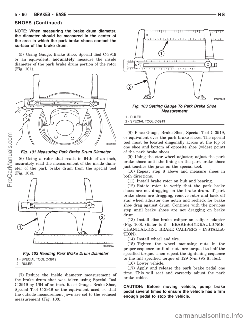
(5) Using Gauge, Brake Shoe, Special Tool C-3919
or an equivalent,accuratelymeasure the inside
diameter of the park brake drum portion of the rotor
(Fig. 101).
(6) Using a ruler that reads in 64th of an inch,
accurately read the measurement of the inside diam-
eter of the park brake drum from the special tool
(Fig. 102).
(7) Reduce the inside diameter measurement of
the brake drum that was taken using Special Tool
C-3919 by 1/64 of an inch. Reset Gauge, Brake Shoe,
Special Tool C-3919 or the equivalent used, so that
the outside measurement jaws are set to the reduced
measurement (Fig. 103).(8) Place Gauge, Brake Shoe, Special Tool C-3919,
or equivalent over the park brake shoes. The special
tool must be located diagonally across at the top of
one shoe and bottom of opposite shoe (widest point)
of the park brake shoes.
(9) Using the star wheel adjuster, adjust the park
brake shoes until the lining on the park brake shoes
just touches the jaws on the special tool.
(10) Repeat step 8 above and measure shoes in
both directions.
(11) Install brake rotor on hub and bearing.
(12) Rotate rotor to verify that the park brake
shoes are not dragging on the brake drum. If park
brake shoes are dragging, remove rotor and back off
star wheel adjuster one notch and recheck for brake
shoe drag against drum. Continue with the previous
step until brake shoes are not dragging on brake
drum.
(13) Install disc brake caliper on caliper adapter
(Fig. 100). (Refer to 5 - BRAKES/HYDRAULIC/ME-
CHANICAL/DISC BRAKE CALIPERS - INSTALLA-
TION).
(14) Install wheel and tire.
(15) Tighten the wheel mounting nuts in the
proper sequence until all nuts are torqued to half the
specified torque. Then repeat the tightening sequence
to the full specified torque of 129 N´m (95 ft. lbs.).
(16) Lower vehicle.
(17) Apply and release the park brake pedal one
time. This will seat and correctly adjust the park
brake cables.
CAUTION: Before moving vehicle, pump brake
pedal several times to ensure the vehicle has a firm
enough pedal to stop the vehicle.
Fig. 101 Measuring Park Brake Drum Diameter
Fig. 102 Reading Park Brake Drum Diameter
1 - SPECIAL TOOL C-3919
2 - RULER
Fig. 103 Setting Gauge To Park Brake Shoe
Measurement
1 - RULER
2 - SPECIAL TOOL C-3919
5 - 60 BRAKES - BASERS
SHOES (Continued)
ProCarManuals.com
Page 224 of 2321
INSTALLATION - PARKING BRAKE CABLE
(FRONT)
(1) Pass front parking brake cable assembly
through hole in floor pan from the inside of the vehi-
cle.
(2) Pass cable strand button through the hole in
the lever (pedal) assembly bracket.
(3) Install cable retainer onto the park brake cable
and then install cable retainer into pedal assembly
bracket.
(4) Install the end of the park brake cable into the
retainer previously installed into the park brake
pedal bracket.
(5) Install cable strand button into the clevis on
the park brake pedal mechanism.
(6) Install the front park brake cable floor pan seal
into hole in floor pan . Seal is to be installed so the
flange on the seal is flush with the floor pan (Fig.
106). Fold carpeting back down on floor.
(7) Raise vehicle.
(8) Insert brake cable and housing into body out-
rigger bracket making certain that housing retainer
fingers lock the housing firmly into place (Fig. 105).
(9) Manually reset the automatic self-adjusting
mechanism tension of the parking brake lever (pedal)
assembly. (Refer to 5 - BRAKES - STANDARD PRO-
CEDURE).
(10) Assemble the park brake cables onto the park
brake cable equalizer (Fig. 104).
(11) Lower vehicle and apply the park brake pedal
1 time. This will seat the parking brake cables.
INSTALLATION - PARKING BRAKE CABLE
(INTERMEDIATE)
(1) Install the ends of the park brake cables
through the frame rails and into the side brackets.
(2) Install the locking nuts at each end of the cable
and securely tighten (Fig. 107) (Fig. 108).
(3) If the vehicle is a short-wheel-base model, it
will be necessary to reinstall the fuel tank to its nor-
mal mounting position. (Refer to 14 - FUEL SYS-
TEM/FUEL DELIVERY/FUEL TANK -
INSTALLATION).(4) Install the intermediate parking brake cable on
the cable connector at the right rear parking brake
cable (Fig. 108).
(5) Install the intermediate park brake cable on
the cable equalizer (Fig. 107).
(6) Remove the locking pliers from the front park
brake cable. This will activate the automatic adjuster
and correctly adjust the parking brake cables.
(7) Install and position the foam collar on the
parking brake cable to prevent it from rattling
against the vehicle's floor.
(8) Lower the vehicle and apply the park brake
pedal 1 time, this will seat the park brake cables.
INSTALLATION - PARKING BRAKE CABLE
(RIGHT REAR)
(1) Install the rear parking brake cable in the
brake support plate. Insert cable housing retainer
into brake support plate making certain that cable
housing retainer fingers lock the housing and
retainer firmly into place.
(2) Attach the parking brake cable onto the park-
ing brake actuator lever.
(3) Install the brake shoes on the rear brake sup-
port plate. (Refer to 5 - BRAKES/HYDRAULIC/ME-
CHANICAL/BRAKE PADS/SHOES -
INSTALLATION).
(4) Insert cable housing retainer into body outrig-
ger bracket making certain that cable housing
retainer fingers lock the housing firmly into place.
(5) Connect the right rear parking brake cable to
the connector on the intermediate parking brake
cable (Fig. 110).
(6) Install the brake drum, then the wheel and tire
assembly.
(7) Remove the locking pliers from the front park
brake cable. This will automatically adjust the park
brake cables.
(8) Lower the vehicle.
(9) Apply and release park brake pedal 1 time.
This will seat the park brake cables.
RSBRAKES - BASE5-65
CABLES (Continued)
ProCarManuals.com
Page 228 of 2321
the rear brake pressure, the outlet valve is switched
off and the inlet valve is pulsed. This increases the
pressure to the rear brakes. This back-and-forth pro-
cess will continue until the required slip difference is
obtained. At the end of EBD braking (brakes
released) the fluid in the LPA drains back to the
master cylinder by switching on the outlet valve and
draining through the inlet valve check valve. At the
same time the inlet valve is switched on in case of
another brake application.
The EBD will remain functional during many ABS
fault modes. If both the red BRAKE, and amber ABS
warning indicators are illuminated, the EBD may not
be functioning.
OPERATION - TRACTION CONTROL SYSTEM
The traction control module monitors wheel speed.
During acceleration, if the module detects front
(drive) wheel slip and the brakes are not applied, the
module enters traction control mode. Traction control
operation proceeds in the following order:
(1) Close the normally open isolation valves.
(2) Start the pump/motor and supply volume and
pressure to the front (drive) hydraulic circuit. (The
pump/motor runs continuously during traction con-
trol operation.)
(3) Open and close the build and decay valves to
maintain minimum wheel slip and maximum trac-
tion.
The cycling of the build and decay valves during
traction control is similar to that during antilock
braking, except the valves work to control wheel spin
by applying the brakes, whereas the ABS function is
to control wheel skid by releasing the brakes.
If the brakes are applied at anytime during a trac-
tion control cycle, the brake lamp switch triggers the
controller to switch off traction control.
HYDRAULIC SHUTTLE VALVES
Two pressure relief hydraulic shuttle valves allow
pressure and volume to return to the master cylinder
reservoir when not consumed by the build and decay
valves. These valves are necessary because the
pump/motor supplies more volume than the system
requires.
TRACTION CONTROL LAMP
The traction control system is enabled at each igni-
tion cycle. It may be turned off by depressing the
Traction Control Off switch button when the ignition
is in the ON position. The traction control function
lamp (TRAC OFF) illuminates immediately upon
depressing the button.
The traction control function lamp illuminates dur-
ing a traction control cycle, displaying TRAC.If the CAB calculates that the brake temperatures
are high, the traction control system becomes inoper-
ative until a time-out period has elapsed. During this
ªthermo-protection mode,º the traction control func-
tion lamp illuminates TRAC OFF; note that no trou-
ble code is registered.
CAUTION
The ABS uses an electronic control module, the
CAB. This module is designed to withstand normal
current draws associated with vehicle operation.
Care must be taken to avoid overloading the CAB
circuits.
CAUTION: In testing for open or short circuits, do
not ground or apply voltage to any of the circuits
unless instructed to do so for a diagnostic proce-
dure.
CAUTION: These circuits should only be tested
using a high impedance multi-meter or the DRBIIIT
scan tool as described in this section. Power
should never be removed or applied to any control
module with the ignition in the ON position. Before
removing or connecting battery cables, fuses, or
connectors, always turn the ignition to the OFF
position.
CAUTION: The CAB 24-way connector should never
be connected or disconnected with the ignition
switch in the ON position.
CAUTION: Use only factory wiring harnesses. Do
not cut or splice wiring to the brake circuits. The
addition of aftermarket electrical equipment (car
phone, radar detector, citizen band radio, trailer
lighting, trailer brakes, etc.) on a vehicle equipped
with antilock brakes may affect the function of the
antilock brake system.
CAUTION: When performing any service procedure
on a vehicle equipped with ABS, do not apply a
12-volt power source to the ground circuit of the
pump motor in the HCU. Doing this will damage the
pump motor and will require replacement of the
entire HCU.
CAUTION: An attempt to remove or disconnect cer-
tain system components may result in improper
system operation. Only those components with
approved removal and installation procedures in
this manual should be serviced.
RSBRAKES - ABS5-69
BRAKES - ABS (Continued)
ProCarManuals.com
Page 232 of 2321

REAR WHEEL SPEED SENSOR
- FWD
REMOVAL - WHEEL SPEED SENSOR
(REAR-FWD)
(1) Raise vehicle. (Refer to LUBRICATION &
MAINTENANCE/HOISTING - STANDARD PROCE-
DURE)
CAUTION: When disconnecting speed sensor cable
from vehicle wiring harness be careful not to dam-
age pins on the electrical connectors. Also, inspect
connectors for any signs of previous damage.
(2) Remove grommet from floor pan of vehicle and
disconnect speed sensor cable connector from vehicle
wiring harness (Fig. 3).
CAUTION: When removing rear wheel speed sensor
cable from routing clips, be sure not to damage the
routing clips. Routing clips that are molded onto
the brake hose will require replacement of the brake
hose if damaged during removal or installation of
the speed sensor cable.
(3) Carefully remove speed sensor cable from
press-in routing clips (Fig. 4).
(4) Remove bolt securing metal routing clip to rear
of axle and remove sensor cable from metal clip (Fig.
4).
(5) Remove secondary (yellow) retaining clip at
rear of wheel speed sensor head (Fig. 5).(6) Push up on metal retaining clip (Fig. 5) until it
bottoms. This will release wheel speed sensor head
from hub and bearing. While holding metal clip up,
pull back on wheel speed sensor head removing it
from hub and bearing.
(7) Remove wheel speed sensor assembly from
vehicle.
Fig. 3 WHEEL SPEED SENSOR CONNECTOR
1 - CONNECTOR
2 - FLOOR PAN
3 - GROMMET
Fig. 4 SPEED SENSOR CABLE ROUTING
1 - METAL CLIP AND MOUNTING BOLT
2 - ROUTING CLIPS
Fig. 5 SENSOR CONNECTION AT HUB AND
BEARING
1 - SECONDARY SENSOR RETAINING CLIP
2 - METAL SENSOR RETAINING CLIP
3 - HUB AND BEARING
RSBRAKES - ABS5-73
ProCarManuals.com
Page 237 of 2321
(2) Inside the vehicle, install the remaining 2
mounting bolts attaching the ICU to the mounting
bracket (Fig. 11). Tighten all 3 mounting bolts to a
torque of 11 N´m (97 in. lbs.).
(3) Install the dash seal and three mounting
screws (Fig. 10).
(4) Install the silencer on top of the dash seal (Fig.
10).
(5) Connect the steering shaft coupling and install
the pinch bolt (Fig. 10). Tighten the pinch bolt to 28
N´m (250 in. lbs.).
(6) Install the silencer panel below the steering
column under the instrument panel.
(7) Remove the steering wheel holder.
CAUTION: Because of the flexible section in the pri-
mary and secondary brake tubes, the brake tubes
must be held in proper orientation when tightened
and torqued. These tubes must not contact each
other or other vehicle components when installed.
Also, after the brake tubes are installed on the HCU,
ensure all spacer clips are reinstalled on the brake
tubes.
(8) Install the primary and secondary brake tubes
into their correct port locations on the HCU valve
block (Fig. 9). Tighten the tube nuts to a torque of 17
N´m (145 in. lbs.).
CAUTION: When installing the chassis brake tubes
on the HCU valve block, they must be located cor-
rectly in the valve block to ensure proper ABS oper-
ation.
NOTE: The chassis brake tube attachment locations
to the HCU, are marked on the bottom of the CAB.
(9) Install the (4) chassis brake tubes into their
correct port locations on the HCU valve block as
shown (Fig. 9). Tighten the tube nuts to a torque of
17 N´m (145 in. lbs.).NOTE: Before installing the 24±way connector in
the CAB be sure the seal is properly installed in the
connector.
(10) Install the 24±way connector on the CAB by,
first, positioning the 24±way connector in the socket
of the CAB and carefully pushing it down as far as
possible. Once connector is fully seated by hand into
the CAB socket, push down on connector lock. This
will pull the connector into the socket of the CAB
and lock it in the installed position.
(11) Install any routing clips on the brake tubes.
(12) Remove the brake pedal holder.
(13) Install the speed control servo with its mount-
ing nuts.
(14) Connect the wiring harness to the speed con-
trol servo.
(15) Install the battery tray (Refer to 8 - ELEC-
TRICAL/BATTERY SYSTEM/TRAY - INSTALLA-
TION).
(16) Install the screw securing the coolant filler
neck to the battery tray.
(17) Reconnect the vacuum hose connector at the
tank built into the battery tray.
(18) Install the battery (Refer to 8 - ELECTRI-
CAL/BATTERY SYSTEM/BATTERY - INSTALLA-
TION).
(19) Install the battery shield.
(20) Remove the brake pedal holder.
(21) Connect negative cable back on negative post
of the battery.
(22) Bleed the Base and ABS brake hydraulic sys-
tems (Refer to 5 - BRAKES - STANDARD PROCE-
DURE).
(23) Road test vehicle to ensure proper operation
of the base and antilock brake systems.
5 - 78 BRAKES - ABSRS
ICU (INTEGRATED CONTROL UNIT) (Continued)
ProCarManuals.com
Page 250 of 2321
INSTALLATION - RHD
(1) Install the ICU on the mounting bracket (Fig.
5). Install the 3 bolts (Fig. 5) attaching the ICU to
the mounting bracket. Tighten the 3 mounting bolts
to a torque of 11 N´m (97 in. lbs.).
CAUTION: The ICU mounting bracket to front sus-
pension cradle mounting bolts have a unique corro-
sion protection coating and a special aluminum
washer. For this reason, only the original, or origi-
nal equipment Mopar replacement bolts can be
used to mount the ICU bracket to the front suspen-
sion crossmember.
(2) Install the ICU and its mounting bracket as an
assembly on the front suspension crossmember.
Install the 3 bolts attaching the ICU bracket to the
crossmember (Fig. 4). Tighten the 3 mounting bolts
to a torque of 28 N´m (250 in. lbs.).
CAUTION: Because of the flexible section in the pri-
mary and secondary brake tubes, and the brake
tubes between the HCU and the proportioning
valve, the brake tubes must be held in proper ori-
entation when tightened and torqued. These tubes
must not contact each other or other vehicle com-
ponents when installed. Also, after the brake tubes
are installed on the HCU, ensure all spacer clips are
reinstalled on the brake tubes.
CAUTION: When installing the chassis brake tubes
on the HCU valve block, they must be located cor-
rectly in the valve block to ensure proper ABS oper-
ation. Refer to (Fig. 3) for the correct chassis brake
tube locations.
NOTE: The chassis brake tube attachment locations
to the HCU, are marked on the bottom of the ICU
mounting bracket.
(3) Install the 6 chassis brake tubes into their cor-
rect port locations on the HCU valve block as shown
in (Fig. 3). Tighten the tube nuts to a torque of 17
N´m (145 in. lbs.).
NOTE: Before installing the 24-way connector in the
CAB be sure the seal is properly installed in the
connector.(4) Install the 24-way connector (Fig. 1) on the
CAB using the following procedure. Position the
24-way connector in the socket of the CAB and care-
fully push it down as far as possible. When connector
is fully seated by hand into the CAB socket, push in
the connector lock (Fig. 2). This will pull the connec-
tor into the socket of the CAB and lock it in the
installed position.
NOTE: The CAB wiring harness must be clipped to
the ICU mounting bracket. This will ensure the wir-
ing harness is properly routed and does not contact
the brake tubes or the body of the vehicle.
(5) Clip the cab wiring harness (Fig. 1) to the ICU
mounting bracket.
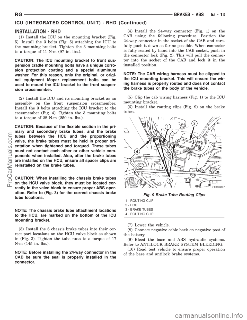
(6) Install the routing clips (Fig. 9) on the brake
tubes.
(7) Lower the vehicle.
(8) Connect negative cable back on negative post of
the battery.
(9) Bleed the base and ABS hydraulic systems.
Refer to ANTILOCK BRAKE SYSTEM BLEEDING.
(10) Road test vehicle to ensure proper operation
of the base and antilock brake systems.
Fig. 9 Brake Tube Routing Clips
1 - ROUTING CLIP
2 - HCU
3 - BRAKE TUBES
4 - ROUTING CLIP
RGBRAKES - ABS5a-13
ICU (INTEGRATED CONTROL UNIT) - RHD (Continued)
ProCarManuals.com