2001 DODGE TOWN AND COUNTRY back
[x] Cancel search: backPage 276 of 2321
CONDITION POSSIBLE CAUSES CORRECTIONS
BELT ROLLED OVER IN GROOVE
OR BELT JUMPS OFF1. Broken cord in belt 1. Replace belt
2. Belt too loose, or too tight 2. (a) Replace belt (auto-tensioned
belts.)
(b) Adjust power steering belt
tension (4 cyl. engine)
3. Misaligned pulleys 3. Align accessories
4. Non-uniform groove or eccentric
pulley4. Replace pulley
DRIVE BELTS - 2.4L
REMOVAL
GENERATOR AND AIR CONDITIONING BELT
(1) Raise vehicle on hoist.
(2) Remove the drive belt shield (Fig. 7).
WARNING: DO NOT ALLOW DRIVE BELT TEN-
SIONER TO SNAP BACK, AS DAMAGE TO TEN-
SIONER AND/OR PERSONAL INJURY COULD
RESULT.
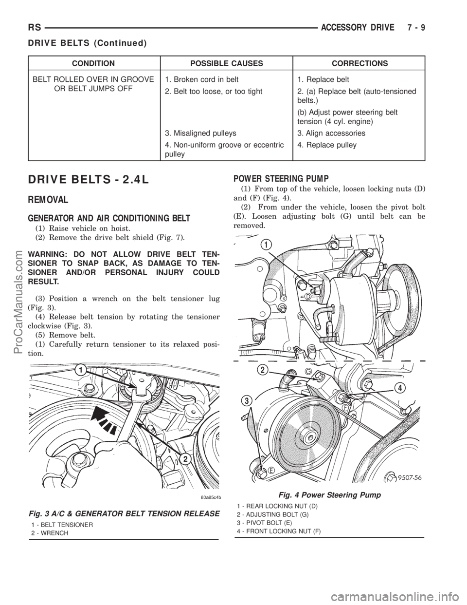
(3) Position a wrench on the belt tensioner lug
(Fig. 3).
(4) Release belt tension by rotating the tensioner
clockwise (Fig. 3).
(5) Remove belt.
(1) Carefully return tensioner to its relaxed posi-
tion.
POWER STEERING PUMP
(1) From top of the vehicle, loosen locking nuts (D)
and (F) (Fig. 4).
(2) From under the vehicle, loosen the pivot bolt
(E). Loosen adjusting bolt (G) until belt can be
removed.
Fig. 3 A/C & GENERATOR BELT TENSION RELEASE
1 - BELT TENSIONER
2 - WRENCH
Fig. 4 Power Steering Pump
1 - REAR LOCKING NUT (D)
2 - ADJUSTING BOLT (G)
3 - PIVOT BOLT (E)
4 - FRONT LOCKING NUT (F)
RSACCESSORY DRIVE7-9
DRIVE BELTS (Continued)
ProCarManuals.com
Page 278 of 2321

DRIVE BELTS - 3.3/3.8L
REMOVAL
(1) Raise vehicle on hoist.
(2) Remove the drive belt shield (Fig. 7).
WARNING: DO NOT ALLOW DRIVE BELT TEN-
SIONER TO SNAP BACK, AS DAMAGE TO TEN-
SIONER AND/OR PERSONAL INJURY COULD
RESULT.
(3) Position a wrench on the belt tensioner lug
(Fig. 8).
(4) Release belt tension by rotating the tensioner
counterclockwise (Fig. 8).(5) Remove the drive belt (Fig. 10).
(6) Carefully return tensioner to its relaxed posi-
tion.CLEANING
Clean all foreign debris from belt pulley grooves.
The belt pulleys must be free of oil, grease, and cool-
ants before installing the drive belt.
INSPECTION
Belt replacement under any or all of the following
conditions is required:
²Excessive wear
²Frayed cords
²Severe glazing
Poly-V Belt system may develop minor cracks
across the ribbed side (due to reverse bending). These
minor cracks are considered normal and acceptable.
Parallel cracks are not (Fig. 9).
NOTE: Do not use any type of belt dressing or
restorer on Poly-V Belts.
Fig. 7 Accessory Drive Belt Shield
1 - ATTACHING SCREW
2 - ATTACHING SCREWS
3 - SPLASH SHIELD
Fig. 8 DRIVE BELT TENSION RELEASE
1 - BLET TENSIONER LUG
2 - WRENCH
Fig. 9 Drive Belt Wear Pattern
1 - NORMAL CRACKS - BELT OK
2 - NOT NORMAL CRACKS - REPLACE BELT
RSACCESSORY DRIVE7-11
ProCarManuals.com
Page 292 of 2321
INSTALLATION
(1)Be sure the air seal is in position before
radiator is installed.Slide radiator down into posi-
tion. Seat the radiator with the rubber isolators into
the mounting holes provided, with a 10 lbs. force.
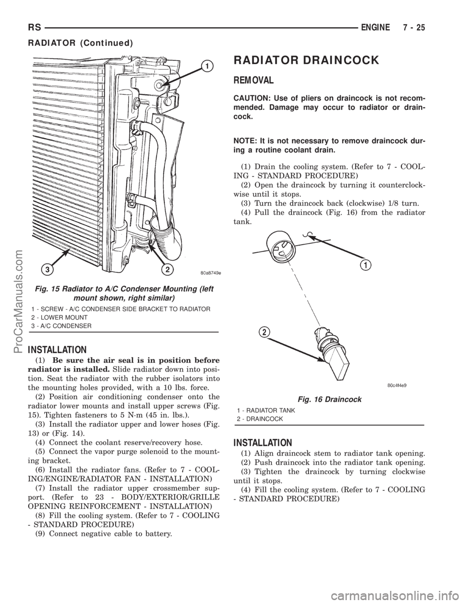
(2) Position air conditioning condenser onto the
radiator lower mounts and install upper screws (Fig.
15). Tighten fasteners to 5 N´m (45 in. lbs.).
(3) Install the radiator upper and lower hoses (Fig.
13) or (Fig. 14).
(4) Connect the coolant reserve/recovery hose.
(5) Connect the vapor purge solenoid to the mount-
ing bracket.
(6) Install the radiator fans. (Refer to 7 - COOL-
ING/ENGINE/RADIATOR FAN - INSTALLATION)
(7) Install the radiator upper crossmember sup-
port. (Refer to 23 - BODY/EXTERIOR/GRILLE
OPENING REINFORCEMENT - INSTALLATION)
(8) Fill the cooling system. (Refer to 7 - COOLING
- STANDARD PROCEDURE)
(9) Connect negative cable to battery.
RADIATOR DRAINCOCK
REMOVAL
CAUTION: Use of pliers on draincock is not recom-
mended. Damage may occur to radiator or drain-
cock.
NOTE: It is not necessary to remove draincock dur-
ing a routine coolant drain.
(1) Drain the cooling system. (Refer to 7 - COOL-
ING - STANDARD PROCEDURE)
(2) Open the draincock by turning it counterclock-
wise until it stops.
(3) Turn the draincock back (clockwise) 1/8 turn.
(4) Pull the draincock (Fig. 16) from the radiator
tank.
INSTALLATION
(1) Align draincock stem to radiator tank opening.
(2) Push draincock into the radiator tank opening.
(3) Tighten the draincock by turning clockwise
until it stops.
(4) Fill the cooling system. (Refer to 7 - COOLING
- STANDARD PROCEDURE)
Fig. 15 Radiator to A/C Condenser Mounting (left
mount shown, right similar)
1 - SCREW - A/C CONDENSER SIDE BRACKET TO RADIATOR
2 - LOWER MOUNT
3 - A/C CONDENSER
Fig. 16 Draincock
1 - RADIATOR TANK
2 - DRAINCOCK
RSENGINE7-25
RADIATOR (Continued)
ProCarManuals.com
Page 293 of 2321
RADIATOR PRESSURE CAP
DESCRIPTION
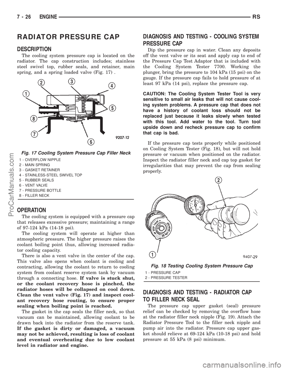
The cooling system pressure cap is located on the
radiator. The cap construction includes; stainless
steel swivel top, rubber seals, and retainer, main
spring, and a spring loaded valve (Fig. 17) .
OPERATION
The cooling system is equipped with a pressure cap
that releases excessive pressure; maintaining a range
of 97-124 kPa (14-18 psi).
The cooling system will operate at higher than
atmospheric pressure. The higher pressure raises the
coolant boiling point thus, allowing increased radia-
tor cooling capacity.
There is also a vent valve in the center of the cap.
This valve also opens when coolant is cooling and
contracting, allowing the coolant to return to cooling
system from coolant reserve system tank by vacuum
through a connecting hose.If valve is stuck shut,
or the coolant recovery hose is pinched, the
radiator hoses will be collapsed on cool down.
Clean the vent valve (Fig. 17) and inspect cool-
ant recovery hose routing, to ensure proper
sealing when boiling point is reached.
The gasket in the cap seals the filler neck, so that
vacuum can be maintained, allowing coolant to be
drawn back into the radiator from the reserve tank.
If the gasket is dirty or damaged, a vacuum
may not be achieved, resulting is loss of coolant
and eventual overheating due to low coolant
level in radiator and engine.
DIAGNOSIS AND TESTING - COOLING SYSTEM
PRESSURE CAP
Dip the pressure cap in water. Clean any deposits
off the vent valve or its seat and apply cap to end of
the Pressure Cap Test Adaptor that is included with
the Cooling System Tester 7700. Working the
plunger, bring the pressure to 104 kPa (15 psi) on the
gauge. If the pressure cap fails to hold pressure of at
least 97 kPa (14 psi), replace the pressure cap.
CAUTION: The Cooling System Tester Tool is very
sensitive to small air leaks that will not cause cool-
ing system problems. A pressure cap that does not
have a history of coolant loss should not be
replaced just because it leaks slowly when tested
with this tool. Add water to the tool. Turn tool
upside down and recheck pressure cap to confirm
that cap is bad.
If the pressure cap tests properly while positioned
on Cooling System Tester (Fig. 18), but will not hold
pressure or vacuum when positioned on the radiator.
Inspect the radiator filler neck and cap top gasket for
irregularities that may prevent the cap from sealing
properly.
DIAGNOSIS AND TESTING - RADIATOR CAP
TO FILLER NECK SEAL
The pressure cap upper gasket (seal) pressure
relief can be checked by removing the overflow hose
at the radiator filler neck nipple (Fig. 19). Attach the
Radiator Pressure Tool to the filler neck nipple and
pump air into the radiator. Pressure cap upper gas-
ket should relieve at 69-124 kPa (10-18 psi) and hold
pressure at 55 kPa (8 psi) minimum.
Fig. 17 Cooling System Pressure Cap Filler Neck
1 - OVERFLOW NIPPLE
2 - MAIN SPRING
3 - GASKET RETAINER
4 - STAINLESS-STEEL SWIVEL TOP
5 - RUBBER SEALS
6 - VENT VALVE
7 - PRESSURE BOTTLE
8 - FILLER NECK
Fig. 18 Testing Cooling System Pressure Cap
1 - PRESSURE CAP
2 - PRESSURE TESTER
7 - 26 ENGINERS
ProCarManuals.com
Page 294 of 2321
WARNING: THE WARNING WORDS ªDO NOT OPEN
HOTº ON THE RADIATOR PRESSURE CAP IS A
SAFETY PRECAUTION. WHEN HOT, PRESSURE
BUILDS UP IN COOLING SYSTEM. TO PREVENT
SCALDING OR INJURY, THE RADIATOR CAP
SHOULD NOT BE REMOVED WHILE THE SYSTEM
IS HOT OR UNDER PRESSURE.
There is no need to remove the radiator cap at any
timeexceptfor the following purposes:
(1) Check and adjust coolant freeze point.
(2) Refill system with new coolant.
(3) Conducting service procedures.
(4) Checking for vacuum leaks.
WARNING: IF VEHICLE HAS BEEN RUN RECENTLY,
WAIT 15 MINUTES BEFORE REMOVING CAP. THEN
PLACE A SHOP TOWEL OVER THE CAP AND WITH-
OUT PUSHING DOWN ROTATE COUNTERCLOCK-
WISE TO THE FIRST STOP. ALLOW FLUIDS TO
ESCAPE THROUGH THE OVERFLOW TUBE AND
WHEN THE SYSTEM STOPS PUSHING COOLANT
AND STEAM INTO THE CRS TANK AND PRESSURE
DROPS PUSH DOWN AND REMOVE THE CAP COM-
PLETELY. SQUEEZING THE RADIATOR INLET HOSE
WITH A SHOP TOWEL (TO CHECK PRESSURE)
BEFORE AND AFTER TURNING TO THE FIRST
STOP IS RECOMMENDED.
CLEANING
Use only a mild soap to clean the pressure cap.
INSPECTION
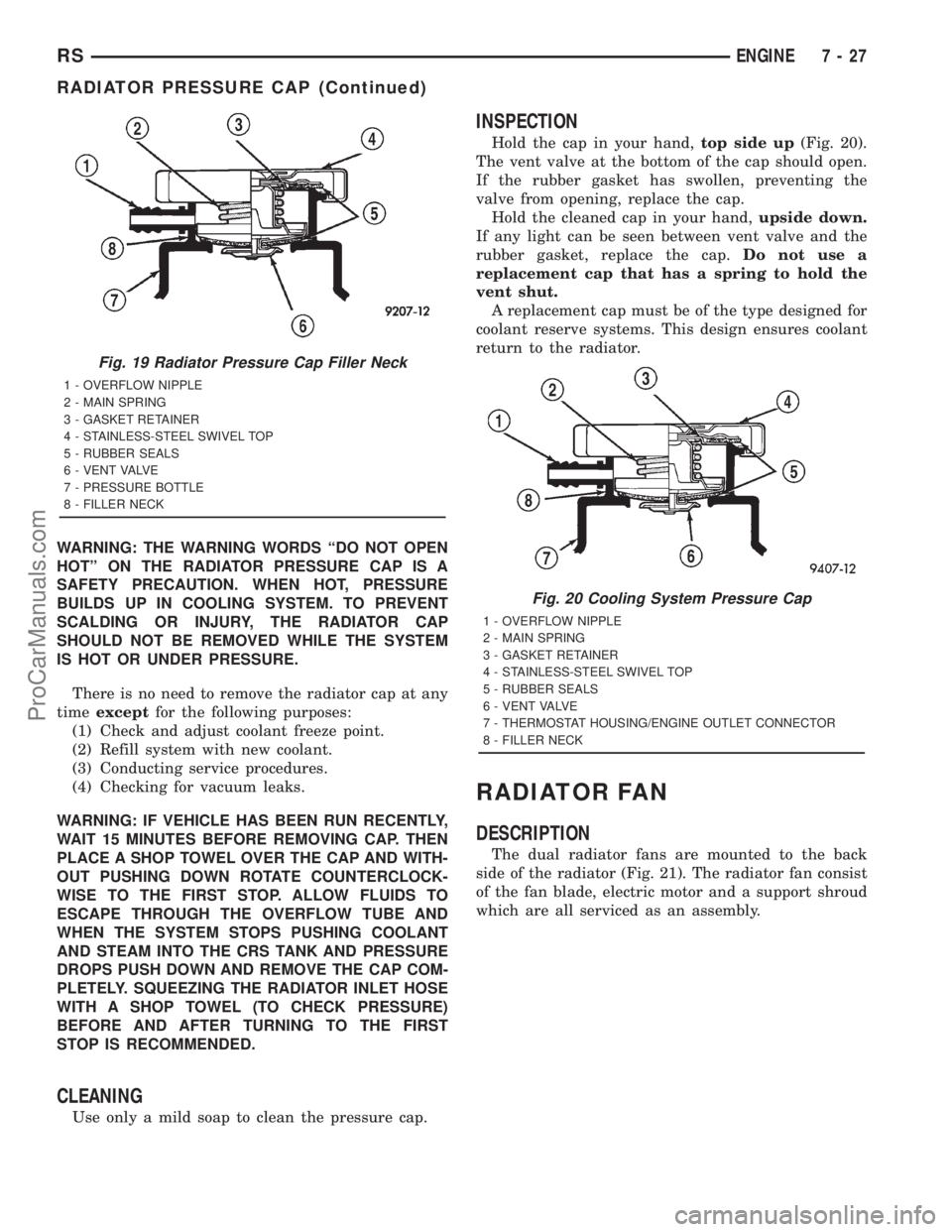
Hold the cap in your hand,top side up(Fig. 20).
The vent valve at the bottom of the cap should open.
If the rubber gasket has swollen, preventing the
valve from opening, replace the cap.
Hold the cleaned cap in your hand,upside down.
If any light can be seen between vent valve and the
rubber gasket, replace the cap.Do not use a
replacement cap that has a spring to hold the
vent shut.
A replacement cap must be of the type designed for
coolant reserve systems. This design ensures coolant
return to the radiator.
RADIATOR FAN
DESCRIPTION
The dual radiator fans are mounted to the back
side of the radiator (Fig. 21). The radiator fan consist
of the fan blade, electric motor and a support shroud
which are all serviced as an assembly.
Fig. 19 Radiator Pressure Cap Filler Neck
1 - OVERFLOW NIPPLE
2 - MAIN SPRING
3 - GASKET RETAINER
4 - STAINLESS-STEEL SWIVEL TOP
5 - RUBBER SEALS
6 - VENT VALVE
7 - PRESSURE BOTTLE
8 - FILLER NECK
Fig. 20 Cooling System Pressure Cap
1 - OVERFLOW NIPPLE
2 - MAIN SPRING
3 - GASKET RETAINER
4 - STAINLESS-STEEL SWIVEL TOP
5 - RUBBER SEALS
6 - VENT VALVE
7 - THERMOSTAT HOUSING/ENGINE OUTLET CONNECTOR
8 - FILLER NECK
RSENGINE7-27
RADIATOR PRESSURE CAP (Continued)
ProCarManuals.com
Page 305 of 2321
TRANS COOLER
DESCRIPTION
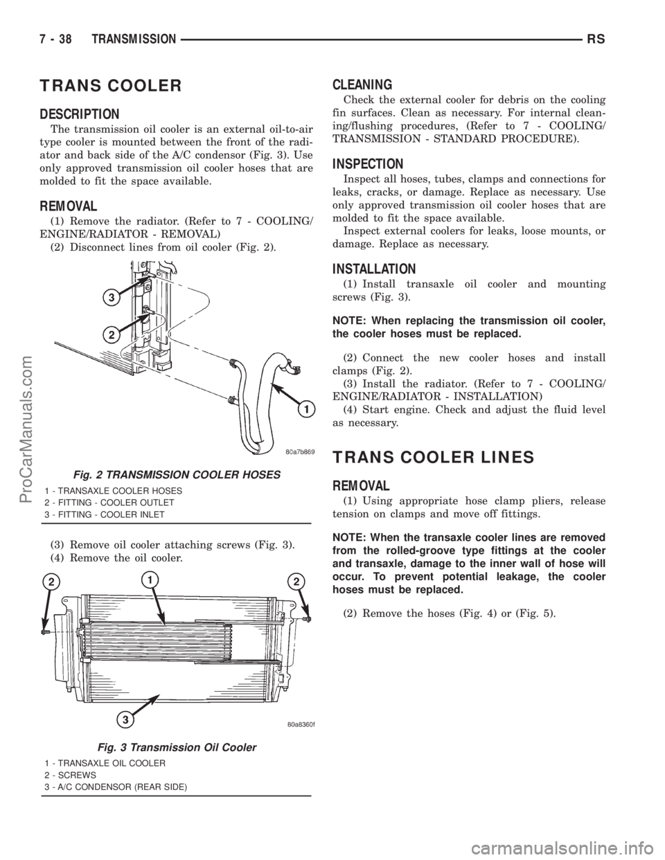
The transmission oil cooler is an external oil-to-air
type cooler is mounted between the front of the radi-
ator and back side of the A/C condensor (Fig. 3). Use
only approved transmission oil cooler hoses that are
molded to fit the space available.
REMOVAL
(1) Remove the radiator. (Refer to 7 - COOLING/
ENGINE/RADIATOR - REMOVAL)
(2) Disconnect lines from oil cooler (Fig. 2).
(3) Remove oil cooler attaching screws (Fig. 3).
(4) Remove the oil cooler.
CLEANING
Check the external cooler for debris on the cooling
fin surfaces. Clean as necessary. For internal clean-
ing/flushing procedures, (Refer to 7 - COOLING/
TRANSMISSION - STANDARD PROCEDURE).
INSPECTION
Inspect all hoses, tubes, clamps and connections for
leaks, cracks, or damage. Replace as necessary. Use
only approved transmission oil cooler hoses that are
molded to fit the space available.
Inspect external coolers for leaks, loose mounts, or
damage. Replace as necessary.
INSTALLATION
(1) Install transaxle oil cooler and mounting
screws (Fig. 3).
NOTE: When replacing the transmission oil cooler,
the cooler hoses must be replaced.
(2) Connect the new cooler hoses and install
clamps (Fig. 2).
(3) Install the radiator. (Refer to 7 - COOLING/
ENGINE/RADIATOR - INSTALLATION)
(4) Start engine. Check and adjust the fluid level
as necessary.
TRANS COOLER LINES
REMOVAL
(1) Using appropriate hose clamp pliers, release
tension on clamps and move off fittings.
NOTE: When the transaxle cooler lines are removed
from the rolled-groove type fittings at the cooler
and transaxle, damage to the inner wall of hose will
occur. To prevent potential leakage, the cooler
hoses must be replaced.
(2) Remove the hoses (Fig. 4) or (Fig. 5).
Fig. 2 TRANSMISSION COOLER HOSES
1 - TRANSAXLE COOLER HOSES
2 - FITTING - COOLER OUTLET
3 - FITTING - COOLER INLET
Fig. 3 Transmission Oil Cooler
1 - TRANSAXLE OIL COOLER
2 - SCREWS
3 - A/C CONDENSOR (REAR SIDE)
7 - 38 TRANSMISSIONRS
ProCarManuals.com
Page 329 of 2321
RADIATOR DRAINCOCK
REMOVAL
CAUTION: Use of pliers on draincock is not recom-
mended. Damage may occur to radiator or drain-
cock.
NOTE: It is not necessary to remove draincock dur-
ing a routine coolant drain.
(1) Drain the cooling system (Refer to 7 - COOL-
ING/ENGINE/COOLANT - STANDARD PROCE-
DURE).
(2) Open the draincock by turning it counterclock-
wise until it stops.
(3) Turn the draincock back (clockwise) 1/8 turn.
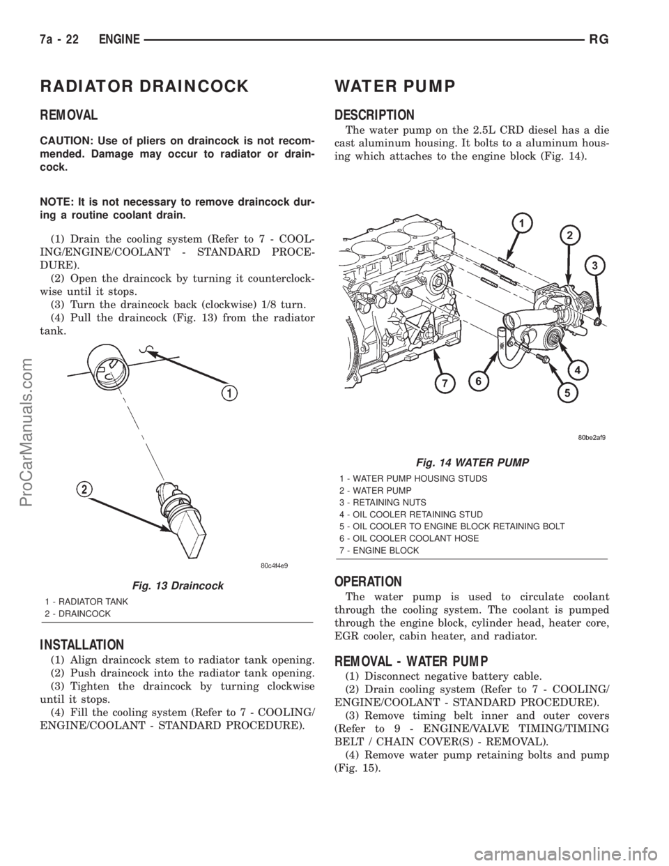
(4) Pull the draincock (Fig. 13) from the radiator
tank.
INSTALLATION
(1) Align draincock stem to radiator tank opening.
(2) Push draincock into the radiator tank opening.
(3) Tighten the draincock by turning clockwise
until it stops.
(4) Fill the cooling system (Refer to 7 - COOLING/
ENGINE/COOLANT - STANDARD PROCEDURE).
WATER PUMP
DESCRIPTION
The water pump on the 2.5L CRD diesel has a die
cast aluminum housing. It bolts to a aluminum hous-
ing which attaches to the engine block (Fig. 14).
OPERATION
The water pump is used to circulate coolant
through the cooling system. The coolant is pumped
through the engine block, cylinder head, heater core,
EGR cooler, cabin heater, and radiator.
REMOVAL - WATER PUMP
(1) Disconnect negative battery cable.
(2) Drain cooling system (Refer to 7 - COOLING/
ENGINE/COOLANT - STANDARD PROCEDURE).
(3) Remove timing belt inner and outer covers
(Refer to 9 - ENGINE/VALVE TIMING/TIMING
BELT / CHAIN COVER(S) - REMOVAL).
(4) Remove water pump retaining bolts and pump
(Fig. 15).
Fig. 13 Draincock
1 - RADIATOR TANK
2 - DRAINCOCK
Fig. 14 WATER PUMP
1 - WATER PUMP HOUSING STUDS
2 - WATER PUMP
3 - RETAINING NUTS
4 - OIL COOLER RETAINING STUD
5 - OIL COOLER TO ENGINE BLOCK RETAINING BOLT
6 - OIL COOLER COOLANT HOSE
7 - ENGINE BLOCK
7a - 22 ENGINERG
ProCarManuals.com
Page 331 of 2321
RADIATOR PRESSURE CAP
DESCRIPTION
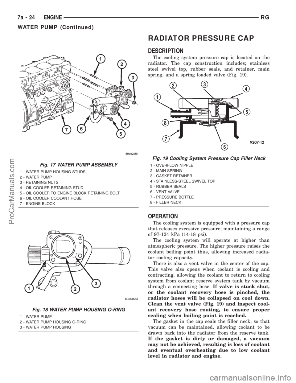
The cooling system pressure cap is located on the
radiator. The cap construction includes; stainless
steel swivel top, rubber seals, and retainer, main
spring, and a spring loaded valve (Fig. 19).
OPERATION
The cooling system is equipped with a pressure cap
that releases excessive pressure; maintaining a range
of 97-124 kPa (14-18 psi).
The cooling system will operate at higher than
atmospheric pressure. The higher pressure raises the
coolant boiling point thus, allowing increased radia-
tor cooling capacity.
There is also a vent valve in the center of the cap.
This valve also opens when coolant is cooling and
contracting, allowing the coolant to return to cooling
system from coolant reserve system tank by vacuum
through a connecting hose.If valve is stuck shut,
or the coolant recovery hose is pinched, the
radiator hoses will be collapsed on cool down.
Clean the vent valve (Fig. 19) and inspect cool-
ant recovery hose routing, to ensure proper
sealing when boiling point is reached.
The gasket in the cap seals the filler neck, so that
vacuum can be maintained, allowing coolant to be
drawn back into the radiator from the reserve tank.
If the gasket is dirty or damaged, a vacuum
may not be achieved, resulting is loss of coolant
and eventual overheating due to low coolant
level in radiator and engine.
Fig. 17 WATER PUMP ASSEMBLY
1 - WATER PUMP HOUSING STUDS
2 - WATER PUMP
3 - RETAINING NUTS
4 - OIL COOLER RETAINING STUD
5 - OIL COOLER TO ENGINE BLOCK RETAINING BOLT
6 - OIL COOLER COOLANT HOSE
7 - ENGINE BLOCK
Fig. 18 WATER PUMP HOUSING O-RING
1 - WATER PUMP
2 - WATER PUMP HOUSING O-RING
3 - WATER PUMP HOUSING
Fig. 19 Cooling System Pressure Cap Filler Neck
1 - OVERFLOW NIPPLE
2 - MAIN SPRING
3 - GASKET RETAINER
4 - STAINLESS-STEEL SWIVEL TOP
5 - RUBBER SEALS
6 - VENT VALVE
7 - PRESSURE BOTTLE
8 - FILLER NECK
7a - 24 ENGINERG
WATER PUMP (Continued)
ProCarManuals.com