2001 DODGE TOWN AND COUNTRY back
[x] Cancel search: backPage 458 of 2321

CAUTION: Cleaning of the platinum plug may dam-
age the platinum tip.
REMOVAL
When replacing the spark plugs and spark plug
cables, route the cables correctly and secure them in
the appropriate retainers. Failure to route the cables
properly can cause the radio to reproduce ignition
noise, cross ignition of the spark plugs orshort cir-
cuit the cables to ground.
Always remove cables by grasping at the boot,
rotating the boot 1/2 turn, and pulling straight back
in a steady motion.
(1) Prior to removing the spark plug, spray com-
pressed air around the spark plug hole and the area
around the spark plug.
(2) Remove the spark plug using a quality socket
with a foam insert.
(3) Inspect the spark plug condition.
INSTALLATION
When replacing the spark plugs and spark plug
cables, route the cables correctly and secure them in
the appropriate retainers. Failure to route the cables
properly can cause the radio to reproduce ignition
noise, cross ignition of the spark plugs orshort cir-
cuit the cables to ground.(1) To avoid cross threading, start the spark plug
into the cylinder head by hand.
(2) Tighten spark plugs to 17.5 N´m (13 ft. lbs.)
torque.
(3) Install spark plug cables over spark plugs. A
click will be heard and felt when the cable properly
attaches to the spark plug.
SPARK PLUG CABLE
DESCRIPTION
Spark Plug cables are sometimes referred to as
secondary ignition wires. The wires transfer electri-
cal current from the ignition coil pack to individual
spark plugs at each cylinder. The resistive spark plug
cables are of nonmetallic construction. The cables
provide suppression of radio frequency emissions
from the ignition system.
Check the spark plug cable connections for good
contact at the coil, and spark plugs. Terminals should
be fully seated. The insulators should be in good con-
dition and should fit tightly on the coil, and spark
plugs. Spark plug cables with insulators that are
cracked or torn must be replaced.
Clean Spark Plug cables with a cloth moistened
with a non-flammable solvent. Wipe the cables dry.
Check for brittle or cracked insulation. The spark
plug cables and spark plug boots are made from high
temperature silicone materials. All spark plug cable
leads are properly identified with cylinder numbers.
The inside of most the spark plug boot is coated with
a special high temperature silicone grease for greater
sealing and to minimize boot bonding to the spark
plug insulator.
REMOVAL
Failure to route the cables properly could cause the
radio to reproduce ignition noise, cross ignition of the
spark plugs or short circuit the cables to ground.
Remove spark plug cable from coil first.
Always remove the spark plug cable by grasping
the top of the spark plug insulator, turning the boot
1/2 turn and pulling straight up in a steady motion.
INSTALLATION
Failure to route the cables properly could cause the
radio to reproduce ignition noise, cross ignition of the
spark plugs or short circuit the cables to ground.
Install spark plug insulators over spark plugs.
Ensure the top of the spark plug insulator covers the
upper end of the spark plug tube.Then connect the
other end to coil pack.
Fig. 15 Setting Spark Plug Electrode Gap
1 - TAPER GAUGE
RSIGNITION CONTROL8I-9
SPARK PLUG (Continued)
ProCarManuals.com
Page 461 of 2321
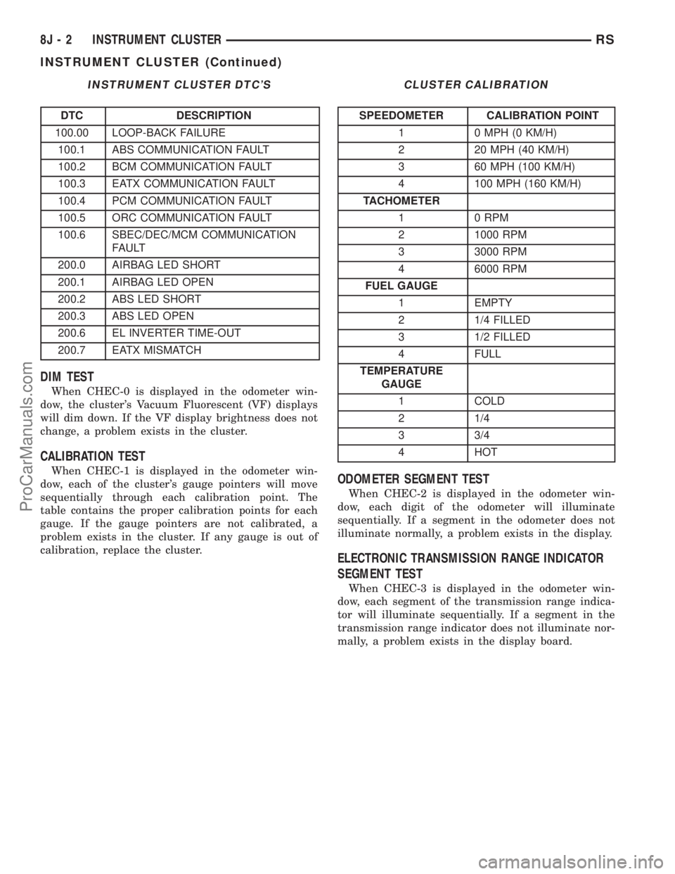
INSTRUMENT CLUSTER DTC'S
DTC DESCRIPTION
100.00 LOOP-BACK FAILURE
100.1 ABS COMMUNICATION FAULT
100.2 BCM COMMUNICATION FAULT
100.3 EATX COMMUNICATION FAULT
100.4 PCM COMMUNICATION FAULT
100.5 ORC COMMUNICATION FAULT
100.6 SBEC/DEC/MCM COMMUNICATION
FAULT
200.0 AIRBAG LED SHORT
200.1 AIRBAG LED OPEN
200.2 ABS LED SHORT
200.3 ABS LED OPEN
200.6 EL INVERTER TIME-OUT
200.7 EATX MISMATCH
DIM TEST
When CHEC-0 is displayed in the odometer win-
dow, the cluster's Vacuum Fluorescent (VF) displays
will dim down. If the VF display brightness does not
change, a problem exists in the cluster.
CALIBRATION TEST
When CHEC-1 is displayed in the odometer win-
dow, each of the cluster's gauge pointers will move
sequentially through each calibration point. The
table contains the proper calibration points for each
gauge. If the gauge pointers are not calibrated, a
problem exists in the cluster. If any gauge is out of
calibration, replace the cluster.
CLUSTER CALIBRATION
SPEEDOMETER CALIBRATION POINT
1 0 MPH (0 KM/H)
2 20 MPH (40 KM/H)
3 60 MPH (100 KM/H)
4 100 MPH (160 KM/H)
TACHOMETER
1 0 RPM
2 1000 RPM
3 3000 RPM
4 6000 RPM
FUEL GAUGE
1 EMPTY
2 1/4 FILLED
3 1/2 FILLED
4 FULL
TEMPERATURE
GAUGE
1 COLD
2 1/4
3 3/4
4 HOT
ODOMETER SEGMENT TEST
When CHEC-2 is displayed in the odometer win-
dow, each digit of the odometer will illuminate
sequentially. If a segment in the odometer does not
illuminate normally, a problem exists in the display.
ELECTRONIC TRANSMISSION RANGE INDICATOR
SEGMENT TEST
When CHEC-3 is displayed in the odometer win-
dow, each segment of the transmission range indica-
tor will illuminate sequentially. If a segment in the
transmission range indicator does not illuminate nor-
mally, a problem exists in the display board.
8J - 2 INSTRUMENT CLUSTERRS
INSTRUMENT CLUSTER (Continued)
ProCarManuals.com
Page 463 of 2321

SPEEDOMETER DIAGNOSIS
CONDITION POSSIBLE CAUSES CORRECTION
NO POINTER
MOVEMENT1. INTERNAL CLUSTER
FAILURE.1.A. PERFORM CLUSTER SELF-DIAGNOSTIC TEST
AND CHECK FOR FAULT CODES.
²IF SPEEDOMETER POINTER MOVES TO
CALIBRATION POINTS DURING TEST LOOK FOR
ANOTHER POSSIBLE CAUSE OF FAILURE.
²IF THE POINTER DOESN'T MOVE DURING TEST,
CHECK FOR POWER AND GROUND TO THE MIC.
IF POWER AND GROUND ARE PRESENT GO TO
STEP 1.B.
1.B. REPLACE CLUSTER. GO TO STEP 1.C.
1.C. CONNECT CLUSTER INTO INSTRUMENT
PANEL WIRING HARNESS. PLACE IT BACK INTO
THE PROPER POSITION IN THE INSTRUMENT
PANEL. PUT IN THE TOP FOUR MOUNTING
SCREWS AND SECURE THE CLUSTER TO THE
INSTRUMENT PANEL.
2. NO SPEED PCI BUS
MESSAGE OR ZERO
MPH PCI SPEED BUS
MESSAGE.2.A. CHECK THE PCM (CODE 10) USING A DRB IIIT
SCAN TOOL. IF OK, GO TO STEP 2.B. IF NOT OK,
REFER TO THE PROPER ENGINE DIAGNOSTIC
PROCEDURES MANUAL TO REPAIR THE PCM.
2.B. CHECK THE SPEED SIGNAL INPUT INTO THE
PCM. THE SPEED SIGNAL ORIGINATES FROM ONE
OF THE FOLLOWING SOURCES:
²A DISTANCE SENSOR FOR VEHICLES WITH 3
SPEED AUTOMATIC TRANSMISSION. CHECK
CONTINUITY FROM DISTANCE SENSOR TO PCM.
IF OK, REPLACE DISTANCE SENSOR. IF NOT OK,
REPAIR WIRING.
²THE TCM FOR VEHICLES WITH THE 4 SPEED
ELECTRONIC TRANSMISSIONS. CHECK
CONTINUITY FROM TCM TO PCM. IF OK, USE A
DRB IIITSCAN TOOL TO CHECK TCM. REFER TO
THE PROPER TRANSMISSION DIAGNOSTIC
PROCEDURES MANUAL TO REPAIR THE TCM. IF
NOT OK, REPAIR WIRING.
8J - 4 INSTRUMENT CLUSTERRS
INSTRUMENT CLUSTER (Continued)
ProCarManuals.com
Page 471 of 2321
(11) Install the lower steering column cover. Refer
to Body, Instrument Panel, Lower Steering Column
Cover, Installation.
(12) Connect the battery negative cable.
CLUSTER LENS
REMOVAL
(1) Remove the instrument cluster. Refer to Elec-
trical, Instrument Cluster, Removal.
(2) Remove the screws holding the lens to the
instrument cluster.
(3) Press down on the snap features of the lens
and remove the lens from the cluster.
INSTALLATION
(1) Insert the lens snap features into the cluster.
(2) Install the screws holding the lens to the
instrument cluster.
(3) Install the instrument cluster. Refer to Electri-
cal, Instrument Cluster, Installation.
MECHANICAL TRANSMISSION
RANGE INDICATOR
REMOVAL
(1) Remove the instrument cluster and disconnect
the range indicator cable at both attaching points.
Refer to Electrical, Instrument Cluster, Removal.
(2) From the backside of the cluster, remove two
screws holding the mechanical transmission rangeindicator and then remove it fromt instrument clus-
ter.
INSTALLATION
(1) Insert the mechanical transmission range indi-
cator into the backside of the instrument cluster and
install the two screws.
(2) Install the instrument cluster. Refer to Electri-
cal, Instrument Cluster, Installation.
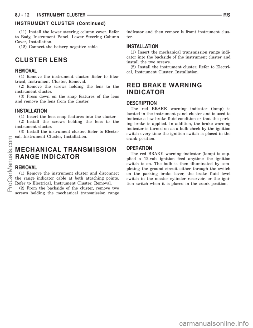
RED BRAKE WARNING
INDICATOR
DESCRIPTION
The red BRAKE warning indicator (lamp) is
located in the instrument panel cluster and is used to
indicate a low brake fluid condition or that the park-
ing brake is applied. In addition, the brake warning
indicator is turned on as a bulb check by the ignition
switch every time the ignition switch is placed in the
crank position.
OPERATION
The red BRAKE warning indicator (lamp) is sup-
plied a 12-volt ignition feed anytime the ignition
switch is on. The bulb is then illuminated by com-
pleting the ground circuit either through the switch
on the parking brake lever, the brake fluid level
switch in the master cylinder reservoir, or the igni-
tion switch when it is placed in the crank position.
8J - 12 INSTRUMENT CLUSTERRS
INSTRUMENT CLUSTER (Continued)
ProCarManuals.com
Page 480 of 2321
SPECIFICATIONS
EXTERIOR LAMPS
CAUTION: Do not use bulbs other than those listed
in the Bulb Application Table. Damage to lamp can
result.
CAUTION: Do not touch halogen bulbs with fingers
or other oily surfaces. Bulb life will be reduced.
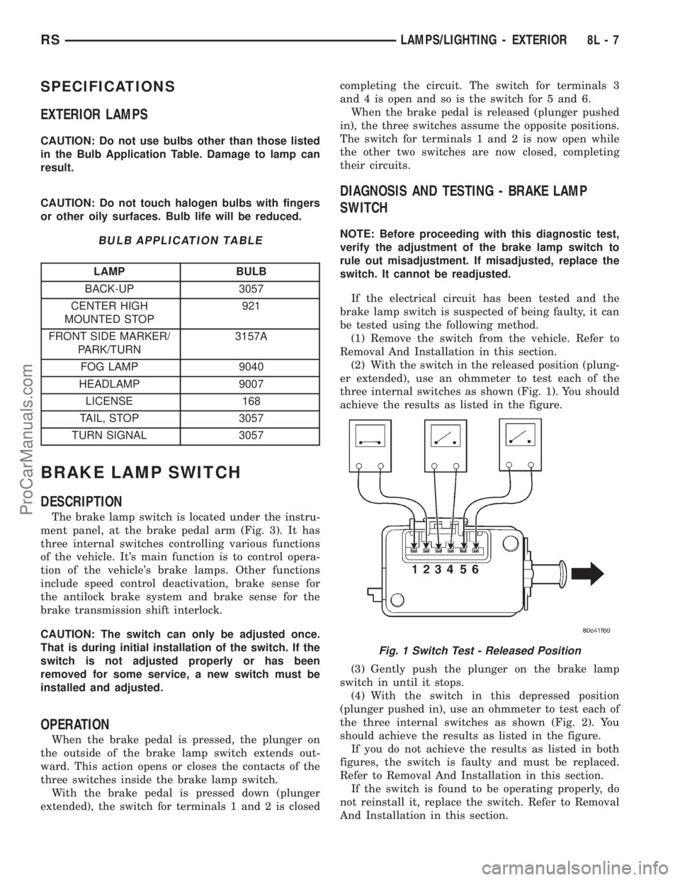
BULB APPLICATION TABLE
LAMP BULB
BACK-UP 3057
CENTER HIGH
MOUNTED STOP921
FRONT SIDE MARKER/
PARK/TURN3157A
FOG LAMP 9040
HEADLAMP 9007
LICENSE 168
TAIL, STOP 3057
TURN SIGNAL 3057
BRAKE LAMP SWITCH
DESCRIPTION
The brake lamp switch is located under the instru-
ment panel, at the brake pedal arm (Fig. 3). It has
three internal switches controlling various functions
of the vehicle. It's main function is to control opera-
tion of the vehicle's brake lamps. Other functions
include speed control deactivation, brake sense for
the antilock brake system and brake sense for the
brake transmission shift interlock.
CAUTION: The switch can only be adjusted once.
That is during initial installation of the switch. If the
switch is not adjusted properly or has been
removed for some service, a new switch must be
installed and adjusted.
OPERATION
When the brake pedal is pressed, the plunger on
the outside of the brake lamp switch extends out-
ward. This action opens or closes the contacts of the
three switches inside the brake lamp switch.
With the brake pedal is pressed down (plunger
extended), the switch for terminals 1 and 2 is closedcompleting the circuit. The switch for terminals 3
and 4 is open and so is the switch for 5 and 6.
When the brake pedal is released (plunger pushed
in), the three switches assume the opposite positions.
The switch for terminals 1 and 2 is now open while
the other two switches are now closed, completing
their circuits.
DIAGNOSIS AND TESTING - BRAKE LAMP
SWITCH
NOTE: Before proceeding with this diagnostic test,
verify the adjustment of the brake lamp switch to
rule out misadjustment. If misadjusted, replace the
switch. It cannot be readjusted.
If the electrical circuit has been tested and the
brake lamp switch is suspected of being faulty, it can
be tested using the following method.
(1) Remove the switch from the vehicle. Refer to
Removal And Installation in this section.
(2) With the switch in the released position (plung-
er extended), use an ohmmeter to test each of the
three internal switches as shown (Fig. 1). You should
achieve the results as listed in the figure.
(3) Gently push the plunger on the brake lamp
switch in until it stops.
(4) With the switch in this depressed position
(plunger pushed in), use an ohmmeter to test each of
the three internal switches as shown (Fig. 2). You
should achieve the results as listed in the figure.
If you do not achieve the results as listed in both
figures, the switch is faulty and must be replaced.
Refer to Removal And Installation in this section.
If the switch is found to be operating properly, do
not reinstall it, replace the switch. Refer to Removal
And Installation in this section.
Fig. 1 Switch Test - Released Position
RSLAMPS/LIGHTING - EXTERIOR8L-7
ProCarManuals.com
Page 481 of 2321
CAUTION: The switch can only be adjusted once.
That is during initial installation of the switch. If the
switch is not adjusted properly or has been
removed for some service, a new switch must be
installed and adjusted.
REMOVAL - BRAKE LAMP SWITCH
(1) Disconnect and isolate the battery negative
cable from its post on the battery.
(2) Remove silencer panel below steering column
and knee blocker.
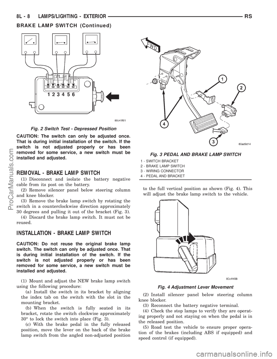
(3) Remove the brake lamp switch by rotating the
switch in a counterclockwise direction approximately
30 degrees and pulling it out of the bracket (Fig. 3).
(4) Discard the brake lamp switch. It must not be
reused.
INSTALLATION - BRAKE LAMP SWITCH
CAUTION: Do not reuse the original brake lamp
switch. The switch can only be adjusted once. That
is during initial installation of the switch. If the
switch is not adjusted properly or has been
removed for some service, a new switch must be
installed and adjusted.
(1) Mount and adjust the NEW brake lamp switch
using the following procedure:
(a) Install the switch in its bracket by aligning
the index tab on the switch with the slot in the
mounting bracket.
(b) When the switch is fully seated in its
bracket, rotate the switch clockwise approximately
30É to lock the switch into place (Fig. 3).
(c) With the brake pedal in the fully released
position, move the lever on the back of the brake
lamp switch from the angled non-adjusted positionto the full vertical position as shown (Fig. 4). This
will adjust the brake lamp switch to the vehicle.
(2) Install silencer panel below steering column
knee blocker.
(3) Reconnect the battery negative terminal.
(4) Check the stop lamps to verify they are operat-
ing properly and not staying on when the pedal is in
the released position.
(5) Road test the vehicle to ensure proper opera-
tion of the brakes (including ABS if equipped) and
speed control (if equipped).
Fig. 2 Switch Test - Depressed Position
Fig. 3 PEDAL AND BRAKE LAMP SWITCH
1 - SWITCH BRACKET
2 - BRAKE LAMP SWITCH
3 - WIRING CONNECTOR
4 - PEDAL AND BRACKET
Fig. 4 Adjustment Lever Movement
8L - 8 LAMPS/LIGHTING - EXTERIORRS
BRAKE LAMP SWITCH (Continued)
ProCarManuals.com
Page 483 of 2321
FOG LAMP UNIT
REMOVAL
(1) Disconnect and isolate the battery negative
cable.
(2) From behind the bumper fascia, disconnect the
wire harness from the fog lamp bulb (Fig. 7).
(3) Remove mounting nuts.
INSTALLATION
(1) Install mounting nuts.
(2) Reconnect the wire harness to the fog lamp
bulb.
(3) Reconnect the battery negative cable.
ADJUSTMENT
FOG LAMP ALIGNMENT
Prepare an alignment screen. (Refer to 8 - ELEC-
TRICAL/LAMPS/LIGHTING - EXTERIOR/HEAD-
LAMP UNIT - ADJUSTMENTS). A properly aligned
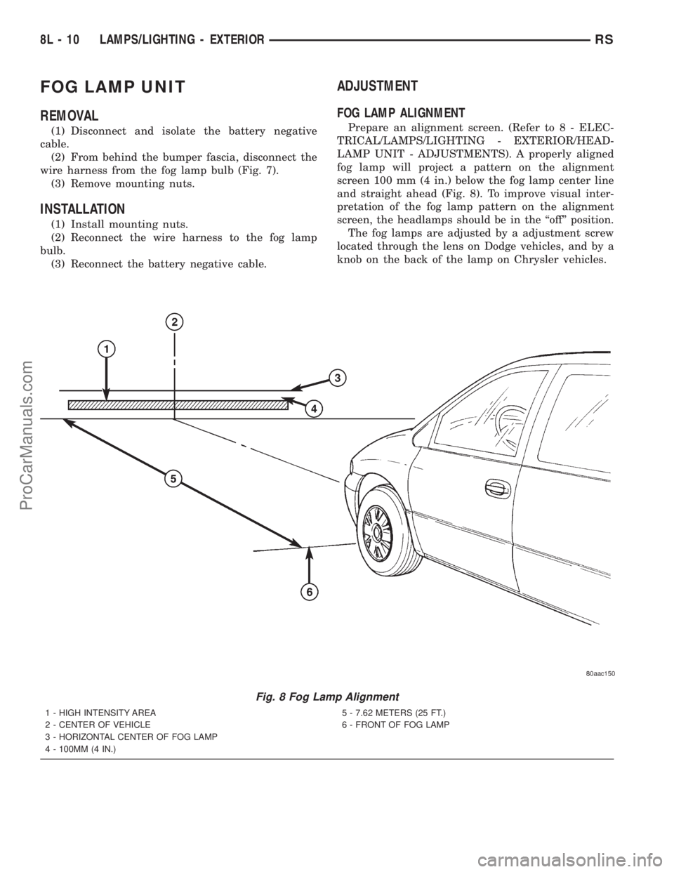
fog lamp will project a pattern on the alignment
screen 100 mm (4 in.) below the fog lamp center line
and straight ahead (Fig. 8). To improve visual inter-
pretation of the fog lamp pattern on the alignment
screen, the headlamps should be in the ªoffº position.
The fog lamps are adjusted by a adjustment screw
located through the lens on Dodge vehicles, and by a
knob on the back of the lamp on Chrysler vehicles.
Fig. 8 Fog Lamp Alignment
1 - HIGH INTENSITY AREA
2 - CENTER OF VEHICLE
3 - HORIZONTAL CENTER OF FOG LAMP
4 - 100MM (4 IN.)5 - 7.62 METERS (25 FT.)
6 - FRONT OF FOG LAMP
8L - 10 LAMPS/LIGHTING - EXTERIORRS
ProCarManuals.com
Page 484 of 2321
HEADLAMP
REMOVAL
(1)Disconnect and isolate the battery negative cable.
(2) Remove headlamp unit retaining screws.
(3) Remove headlamp unit to expose back of unit.
(4) Remove wiring connector from bulb.
(5) Rotate headlamp bulb retaining ring counter-
clockwise.
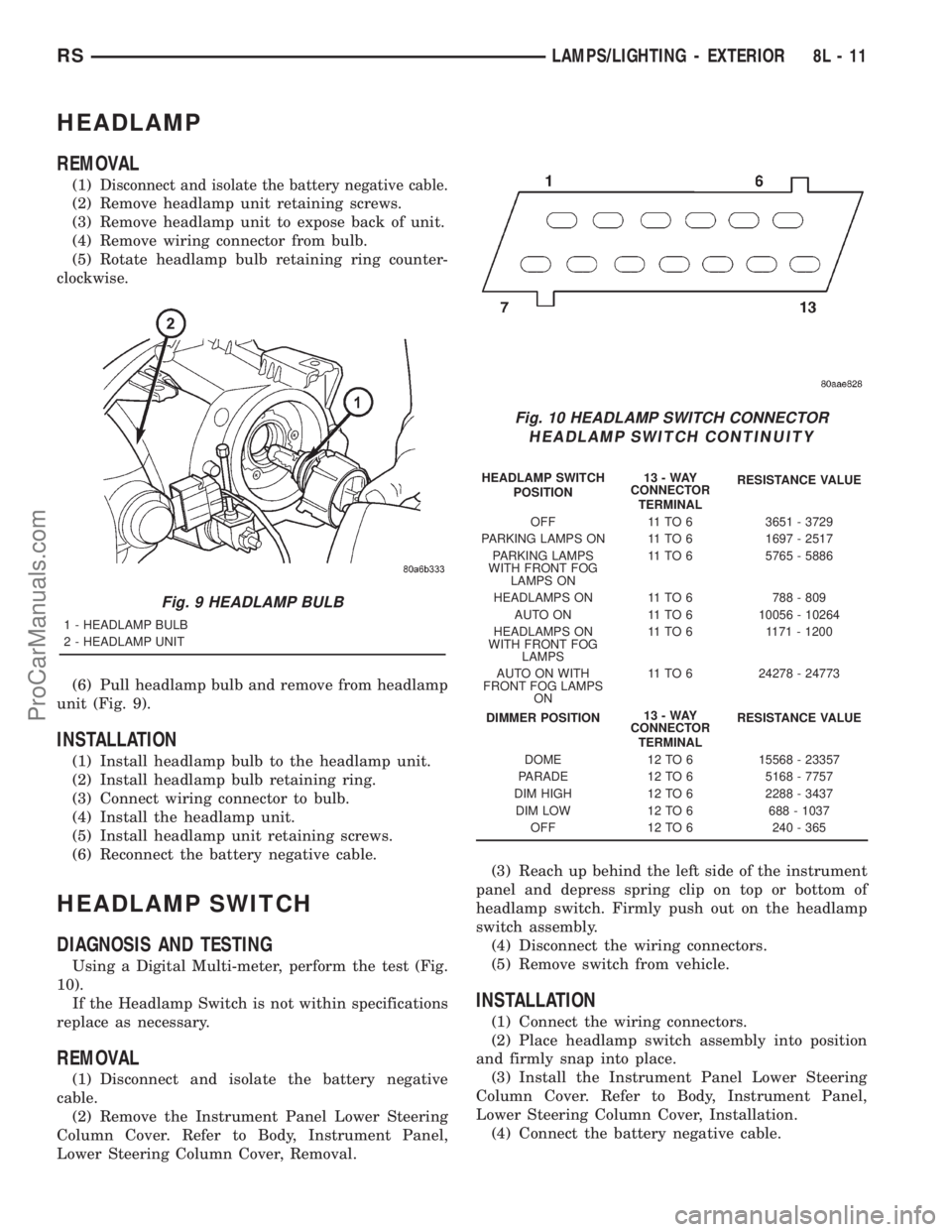
(6) Pull headlamp bulb and remove from headlamp
unit (Fig. 9).
INSTALLATION
(1) Install headlamp bulb to the headlamp unit.
(2) Install headlamp bulb retaining ring.
(3) Connect wiring connector to bulb.
(4) Install the headlamp unit.
(5) Install headlamp unit retaining screws.
(6) Reconnect the battery negative cable.
HEADLAMP SWITCH
DIAGNOSIS AND TESTING
Using a Digital Multi-meter, perform the test (Fig.
10).
If the Headlamp Switch is not within specifications
replace as necessary.
REMOVAL
(1) Disconnect and isolate the battery negative
cable.
(2) Remove the Instrument Panel Lower Steering
Column Cover. Refer to Body, Instrument Panel,
Lower Steering Column Cover, Removal.(3) Reach up behind the left side of the instrument
panel and depress spring clip on top or bottom of
headlamp switch. Firmly push out on the headlamp
switch assembly.
(4) Disconnect the wiring connectors.
(5) Remove switch from vehicle.
INSTALLATION
(1) Connect the wiring connectors.
(2) Place headlamp switch assembly into position
and firmly snap into place.
(3) Install the Instrument Panel Lower Steering
Column Cover. Refer to Body, Instrument Panel,
Lower Steering Column Cover, Installation.
(4) Connect the battery negative cable.
Fig. 9 HEADLAMP BULB
1 - HEADLAMP BULB
2 - HEADLAMP UNIT
Fig. 10 HEADLAMP SWITCH CONNECTOR
HEADLAMP SWITCH CONTINUITY
HEADLAMP SWITCH
POSITION13-WAY
CONNECTOR
TERMINALRESISTANCE VALUE
OFF 11 TO 6 3651 - 3729
PARKING LAMPS ON 11 TO 6 1697 - 2517
PARKING LAMPS
WITH FRONT FOG
LAMPS ON11 TO 6 5765 - 5886
HEADLAMPS ON 11 TO 6 788 - 809
AUTO ON 11 TO 6 10056 - 10264
HEADLAMPS ON
WITH FRONT FOG
LAMPS11 TO 6 1171 - 1200
AUTO ON WITH
FRONT FOG LAMPS
ON11 TO 6 24278 - 24773
DIMMER POSITION13-WAY
CONNECTOR
TERMINALRESISTANCE VALUE
DOME 12 TO 6 15568 - 23357
PARADE 12 TO 6 5168 - 7757
DIM HIGH 12 TO 6 2288 - 3437
DIM LOW 12 TO 6 688 - 1037
OFF 12 TO 6 240 - 365
RSLAMPS/LIGHTING - EXTERIOR8L-11
ProCarManuals.com