2001 DODGE TOWN AND COUNTRY back
[x] Cancel search: backPage 2285 of 2321
put component, it can verify that the command was
carried out by monitoring specific input signals for
expected changes. For example, when the PCM com-
mands the Idle Air Control (IAC) Motor to a specific
position under certain operating conditions, it expects
to see a specific (target) idle speed (RPM). If it does
not, it stores a DTC.
PCM outputs monitored for functionality include:
²Fuel Injectors
²Ignition Coils
²Torque Converter Clutch Solenoid
²Idle Air Control
²Purge Solenoid
²EGR Solenoid
²LDP Solenoid
²Radiator Fan Control
²Trans Controls
OXYGEN SENSOR (O2S) MONITOR
DESCRIPTIONÐEffective control of exhaust
emissions is achieved by an oxygen feedback system.
The most important element of the feedback system
is the O2S. The O2S is located in the exhaust path.
Once it reaches operating temperature 300É to 350ÉC
(572É to 662ÉF), the sensor generates a voltage that
is inversely proportional to the amount of oxygen in
the exhaust. When there is a large amount of oxygen
in the exhaust caused by a lean condition, the sensor
produces a low voltage, below 450 mV. When the oxy-
gen content is lower, caused by a rich condition, the
sensor produces a higher voltage, above 450mV.
The information obtained by the sensor is used to
calculate the fuel injector pulse width. The PCM is
programmed to maintain the optimum air/fuel ratio.
At this mixture ratio, the catalyst works best to
remove hydrocarbons (HC), carbon monoxide (CO)
and nitrous oxide (NOx) from the exhaust.
The O2S is also the main sensing element for the
EGR, Catalyst and Fuel Monitors.
The O2S may fail in any or all of the following
manners:
²Slow response rate (Big Slope)
²Reduced output voltage (Half Cycle)
²Heater Performance
Slow Response Rate (Big Slope)ÐResponse rate
is the time required for the sensor to switch from
lean to rich signal output once it is exposed to a
richer than optimum A/F mixture or vice versa. As
the PCM adjusts the air/fuel ratio, the sensor must
be able to rapidly detect the change. As the sensor
ages, it could take longer to detect the changes in the
oxygen content of the exhaust gas. The rate of
change that an oxygen sensor experiences is called
'Big Slope'. The PCM checks the oxygen sensor volt-
age in increments of a few milliseconds.Reduced Output Voltage (Half Cycle)ÐThe
output voltage of the O2S ranges from 0 to 1 volt. A
good sensor can easily generate any output voltage in
this range as it is exposed to different concentrations
of oxygen. To detect a shift in the A/F mixture (lean
or rich), the output voltage has to change beyond a
threshold value. A malfunctioning sensor could have
difficulty changing beyond the threshold value. Each
time the voltage signal surpasses the threshold, a
counter is incremented by one. This is called the Half
Cycle Counter.
Heater PerformanceÐThe heater is tested by a
separate monitor. Refer to the Oxygen Sensor Heater
Monitor.
OPERATIONÐAs the Oxygen Sensor signal
switches, the PCM monitors the half cycle and big
slope signals from the oxygen sensor. If during the
test neither counter reaches a predetermined value, a
malfunction is entered and a Freeze Frame is stored.
Only one counter reaching its predetermined value is
needed for the monitor to pass.
The Oxygen Sensor Monitor is a two trip monitor
that is tested only once per trip. When the Oxygen
Sensor fails the test in two consecutive trips, the
MIL is illuminated and a DTC is set. The MIL is
extinguished when the Oxygen Sensor monitor
passes in three consecutive trips. The DTC is erased
from memory after 40 consecutive warm-up cycles
without test failure.
Enabling ConditionsÐThe following conditions
must typically be met for the PCM to run the oxygen
sensor monitor:
²Battery voltage
²Engine temperature
²Engine run time
²Engine run time at a predetermined speed
²Engine run time at a predetermined speed and
throttle opening
²Transmission in gear (automatic only)
²Fuel system in Closed Loop
²Long Term Adaptive (within parameters)
²Power Steering Switch in low PSI (no load)
²Engine at idle
²Fuel level above 15%
²Ambient air temperature
²Barometric pressure
²Engine RPM within acceptable range of desired
idle
²Closed throttle speed
Pending ConditionsÐThe Task Manager typi-
cally does not run the Oxygen Sensor Monitor if over-
lapping monitors are running or the MIL is
illuminated for any of the following:
²Misfire Monitor
²Front Oxygen Sensor and Heater Monitor
²MAP Sensor
25 - 2 EMISSIONS CONTROLRS
EMISSIONS CONTROL (Continued)
ProCarManuals.com
Page 2289 of 2321
VACUUM ASSIST
The PCM cannot detect leaks or restrictions in the
vacuum circuits of vacuum assisted engine control
system devices. However, these could cause the PCM
to store a MAP sensor diagnostic trouble code and
cause a high idle condition.
PCM SYSTEM GROUND
The PCM cannot determine a poor system ground.
However, one or more diagnostic trouble codes may
be generated as a result of this condition. The mod-
ule should be mounted to the body at all times, also
during diagnostic.
PCM CONNECTOR ENGAGEMENT
The PCM may not be able to determine spread or
damaged connector pins. However, it might store
diagnostic trouble codes as a result of spread connec-
tor pins.
DESCRIPTION - MONITORED SYSTEMS
There are new electronic circuit monitors that
check fuel, emission, engine and ignition perfor-
mance. These monitors use information from various
sensor circuits to indicate the overall operation of the
fuel, engine, ignition and emission systems and thus
the emissions performance of the vehicle.
The fuel, engine, ignition and emission systems
monitors do not indicate a specific component prob-
lem. They do indicate that there is an implied prob-
lem within one of the systems and that a specific
problem must be diagnosed.
If any of these monitors detect a problem affecting
vehicle emissions, the Malfunction Indicator (Check
Engine) Lamp will be illuminated. These monitors
generate Diagnostic Trouble Codes that can be dis-
played with the check engine lamp or a scan tool.
The following is a list of the system monitors:
²EGR Monitor
²Misfire Monitor
²Fuel System Monitor
²Oxygen Sensor Monitor
²Oxygen Sensor Heater Monitor
²Catalyst Monitor
²Evaporative System Leak Detection Monitor
Following is a description of each system monitor,
and its DTC.
Refer to the appropriate Powertrain Diagnos-
tics Procedures manual for diagnostic proce-
dures.
OXYGEN SENSOR (O2S) MONITOR
Effective control of exhaust emissions is achieved
by an oxygen feedback system. The most important
element of the feedback system is the O2S. The O2S
is located in the exhaust path. Once it reaches oper-ating temperatures of 300É to 350ÉC (572É to 662ÉF),
the sensor generates a voltage that is inversely pro-
portional to the amount of oxygen in the exhaust.
The information obtained by the sensor is used to
calculate the fuel injector pulse width. The PCM is
programmed to maintain the optimum air/fuel ratio.
At this mixture ratio, the catalyst works best to
remove hydrocarbons (HC), carbon monoxide (CO)
and nitrous oxide (NOx) from the exhaust.
The O2S is also the main sensing element for the
EGR, Catalyst and Fuel Monitors.
The O2S may fail in any or all of the following
manners:
²Slow response rate
²Reduced output voltage
²Dynamic shift
²Shorted or open circuits
Response rate is the time required for the sensor to
switch from lean to rich once it is exposed to a richer
than optimum A/F mixture or vice versa. As the sen-
sor starts malfunctioning, it could take longer to
detect the changes in the oxygen content of the
exhaust gas.
The output voltage of the O2S ranges from 0 to 1
volt. A good sensor can easily generate any output
voltage in this range as it is exposed to different con-
centrations of oxygen. To detect a shift in the A/F
mixture (lean or rich), the output voltage has to
change beyond a threshold value. A malfunctioning
sensor could have difficulty changing beyond the
threshold value.
OXYGEN SENSOR HEATER MONITOR
If there is an oxygen sensor (O2S) DTC as well as
a O2S heater DTC, the O2S fault MUST be repaired
first. After the O2S fault is repaired, verify that the
heater circuit is operating correctly.
Effective control of exhaust emissions is achieved
by an oxygen feedback system. The most important
element of the feedback system is the O2S. The O2S
is located in the exhaust path. Once it reaches oper-
ating temperatures of 300É to 350ÉC (572 É to 662ÉF),
the sensor generates a voltage that is inversely pro-
portional to the amount of oxygen in the exhaust.
The information obtained by the sensor is used to
calculate the fuel injector pulse width. This main-
tains a 14.7 to 1 Air Fuel (A/F) ratio. At this mixture
ratio, the catalyst works best to remove hydrocarbons
(HC), carbon monoxide (CO) and nitrogen oxide
(NOx) from the exhaust.
The voltage readings taken from the O2S are very
temperature sensitive. The readings are not accurate
below 300ÉC. Heating of the O2S is done to allow the
engine controller to shift to closed loop control as
soon as possible. The heating element used to heat
25 - 6 EMISSIONS CONTROLRS
EMISSIONS CONTROL (Continued)
ProCarManuals.com
Page 2298 of 2321
ORVR
OPERATION
The emission control principle used in the ORVR sys-
tem is that the fuel flowing into the filler tube (appx. 1º
I.D.) creates an aspiration effect which draws air into
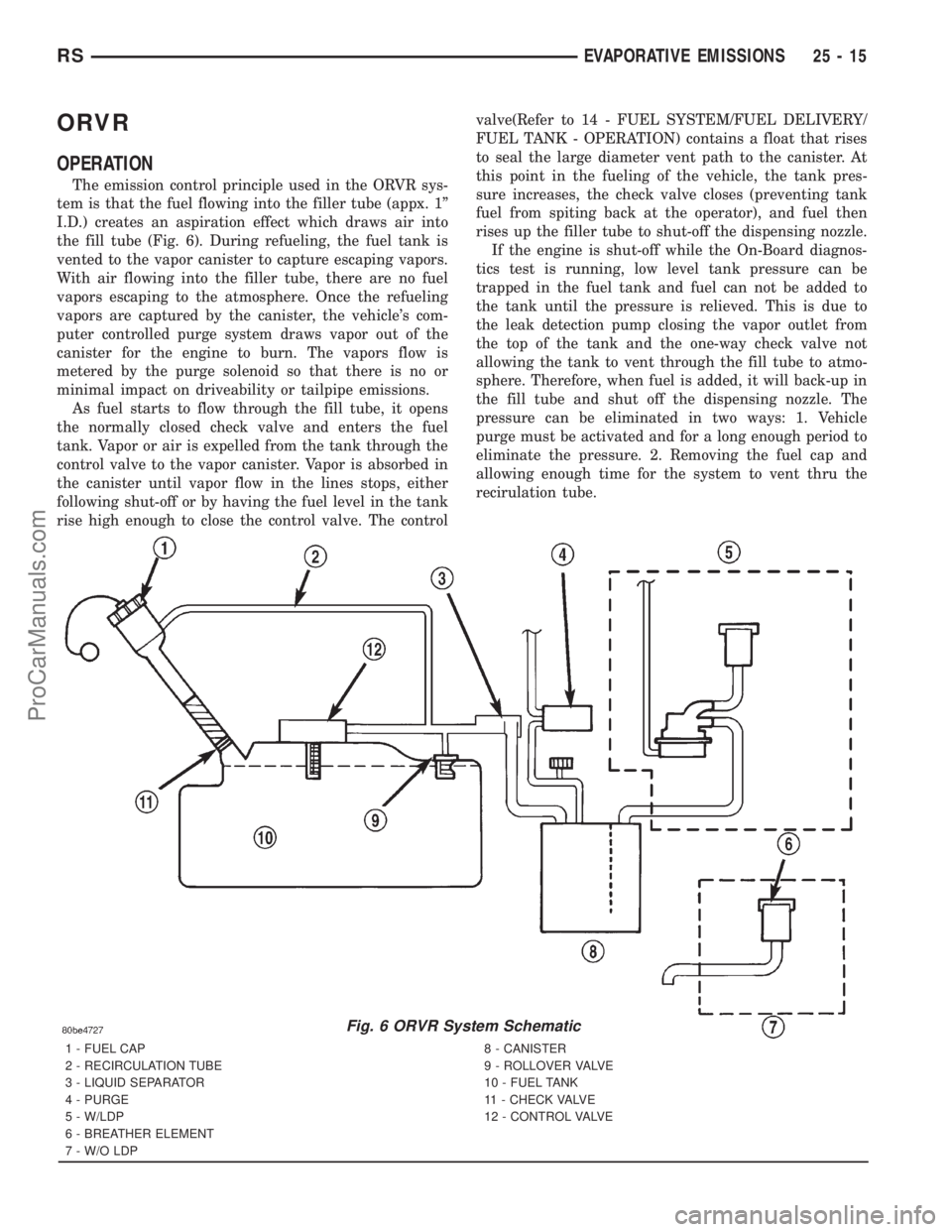
the fill tube (Fig. 6). During refueling, the fuel tank is
vented to the vapor canister to capture escaping vapors.
With air flowing into the filler tube, there are no fuel
vapors escaping to the atmosphere. Once the refueling
vapors are captured by the canister, the vehicle's com-
puter controlled purge system draws vapor out of the
canister for the engine to burn. The vapors flow is
metered by the purge solenoid so that there is no or
minimal impact on driveability or tailpipe emissions.
As fuel starts to flow through the fill tube, it opens
the normally closed check valve and enters the fuel
tank. Vapor or air is expelled from the tank through the
control valve to the vapor canister. Vapor is absorbed in
the canister until vapor flow in the lines stops, either
following shut-off or by having the fuel level in the tank
rise high enough to close the control valve. The controlvalve(Refer to 14 - FUEL SYSTEM/FUEL DELIVERY/
FUEL TANK - OPERATION) contains a float that rises
to seal the large diameter vent path to the canister. At
this point in the fueling of the vehicle, the tank pres-
sure increases, the check valve closes (preventing tank
fuel from spiting back at the operator), and fuel then
rises up the filler tube to shut-off the dispensing nozzle.
If the engine is shut-off while the On-Board diagnos-
tics test is running, low level tank pressure can be
trapped in the fuel tank and fuel can not be added to
the tank until the pressure is relieved. This is due to
the leak detection pump closing the vapor outlet from
the top of the tank and the one-way check valve not
allowing the tank to vent through the fill tube to atmo-
sphere. Therefore, when fuel is added, it will back-up in
the fill tube and shut off the dispensing nozzle. The
pressure can be eliminated in two ways: 1. Vehicle
purge must be activated and for a long enough period to
eliminate the pressure. 2. Removing the fuel cap and
allowing enough time for the system to vent thru the
recirulation tube.
Fig. 6 ORVR System Schematic
1 - FUEL CAP
2 - RECIRCULATION TUBE
3 - LIQUID SEPARATOR
4 - PURGE
5 - W/LDP
6 - BREATHER ELEMENT
7 - W/O LDP8 - CANISTER
9 - ROLLOVER VALVE
10 - FUEL TANK
11 - CHECK VALVE
12 - CONTROL VALVE
RSEVAPORATIVE EMISSIONS25-15
ProCarManuals.com
Page 2300 of 2321
PCV VALVE
DESCRIPTION
The PCV valve contains a spring loaded plunger.
The plunger meters the amount of crankcase vapors
routed into the combustion chamber based on intake
manifold vacuum.
OPERATION
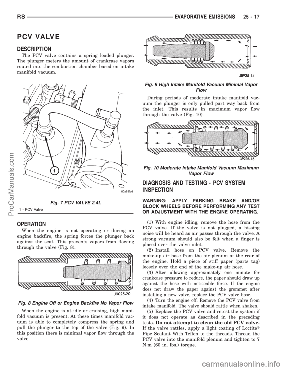
When the engine is not operating or during an
engine backfire, the spring forces the plunger back
against the seat. This prevents vapors from flowing
through the valve (Fig. 8).
When the engine is at idle or cruising, high mani-
fold vacuum is present. At these times manifold vac-
uum is able to completely compress the spring and
pull the plunger to the top of the valve (Fig. 9). In
this position there is minimal vapor flow through the
valve.During periods of moderate intake manifold vac-
uum the plunger is only pulled part way back from
the inlet. This results in maximum vapor flow
through the valve (Fig. 10).
DIAGNOSIS AND TESTING - PCV SYSTEM
INSPECTION
WARNING: APPLY PARKING BRAKE AND/OR
BLOCK WHEELS BEFORE PERFORMING ANY TEST
OR ADJUSTMENT WITH THE ENGINE OPERATING.
(1) With engine idling, remove the hose from the
PCV valve. If the valve is not plugged, a hissing
noise will be heard as air passes through the valve. A
strong vacuum should also be felt when a finger is
placed over the valve inlet.
(2) Install hose on PCV valve. Remove the
make-up air hose from the air plenum at the rear of
the engine. Hold a piece of stiff paper (parts tag)
loosely over the end of the make-up air hose.
(3)
After allowing approximately one minute for
crankcase pressure to reduce, the paper should draw up
against the hose with noticeable force. If the engine
does not draw the paper against the grommet after
installing a new valve, replace the PCV valve hose.
(4)Turn the engine off. Remove the PCV valve from
intake manifold. The valve should rattle when shaken.
(5) Replace the PCV valve and retest the system if
it does not operate as described in the preceding
tests.Do not attempt to clean the old PCV valve.
If the valve rattles, apply a light coating of Loctitet
Pipe Sealant With Teflon to the threads. Thread the
PCV valve into the manifold plenum and tighten to 7
N´m (60 in. lbs.) torque.
Fig. 7 PCV VALVE 2.4L
1 - PCV Valve
Fig. 8 Engine Off or Engine Backfire No Vapor Flow
Fig. 9 High Intake Manifold Vacuum Minimal Vapor
Flow
Fig. 10 Moderate Intake Manifold Vacuum Maximum
Vapor Flow
RSEVAPORATIVE EMISSIONS25-17
ProCarManuals.com
Page 2304 of 2321
NOTE: If you have a striped bolt at the Intake man-
ifold (Refer to 9 - ENGINE - STANDARD PROCE-
DURE) for thread repair.
INSTALLATION - 3.8L
(1) Loose install EGR tube and gasket with attach-
ing bolts at intake manifold.
(2) Loose install EGR tube and gasket with attach-
ing bolts at EGR valve.
(3) Tighten bolts to EGR valve to 11.9 N´m (105
620 ins. lbs.).
(4) Tighten bolts to Intake manifold to 11.9 N´m
(105620 ins. lbs.).
VA LV E
DESCRIPTION
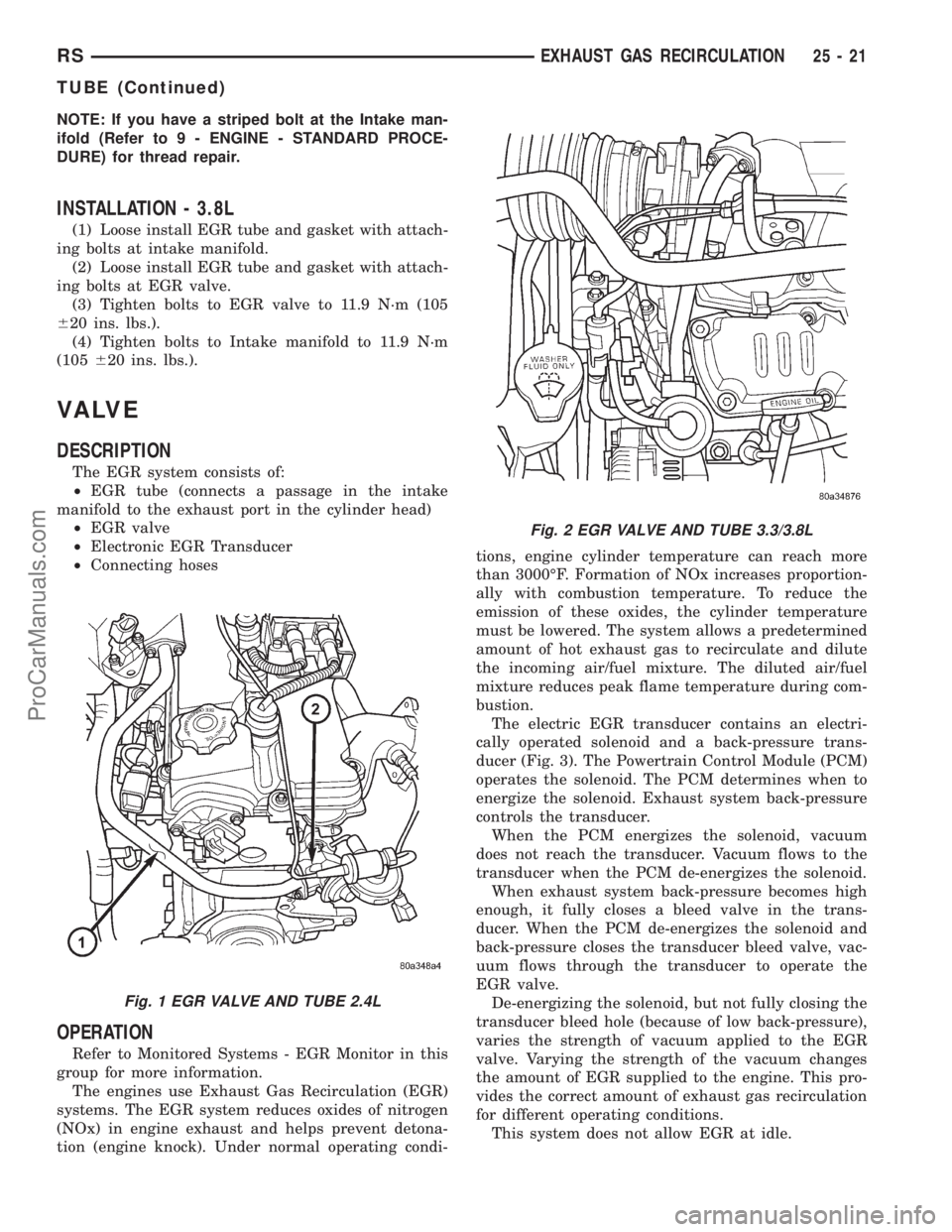
The EGR system consists of:
²EGR tube (connects a passage in the intake
manifold to the exhaust port in the cylinder head)
²EGR valve
²Electronic EGR Transducer
²Connecting hoses
OPERATION
Refer to Monitored Systems - EGR Monitor in this
group for more information.
The engines use Exhaust Gas Recirculation (EGR)
systems. The EGR system reduces oxides of nitrogen
(NOx) in engine exhaust and helps prevent detona-
tion (engine knock). Under normal operating condi-tions, engine cylinder temperature can reach more
than 3000ÉF. Formation of NOx increases proportion-
ally with combustion temperature. To reduce the
emission of these oxides, the cylinder temperature
must be lowered. The system allows a predetermined
amount of hot exhaust gas to recirculate and dilute
the incoming air/fuel mixture. The diluted air/fuel
mixture reduces peak flame temperature during com-
bustion.
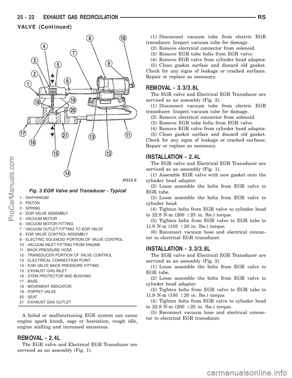
The electric EGR transducer contains an electri-
cally operated solenoid and a back-pressure trans-
ducer (Fig. 3). The Powertrain Control Module (PCM)
operates the solenoid. The PCM determines when to
energize the solenoid. Exhaust system back-pressure
controls the transducer.
When the PCM energizes the solenoid, vacuum
does not reach the transducer. Vacuum flows to the
transducer when the PCM de-energizes the solenoid.
When exhaust system back-pressure becomes high
enough, it fully closes a bleed valve in the trans-
ducer. When the PCM de-energizes the solenoid and
back-pressure closes the transducer bleed valve, vac-
uum flows through the transducer to operate the
EGR valve.
De-energizing the solenoid, but not fully closing the
transducer bleed hole (because of low back-pressure),
varies the strength of vacuum applied to the EGR
valve. Varying the strength of the vacuum changes
the amount of EGR supplied to the engine. This pro-
vides the correct amount of exhaust gas recirculation
for different operating conditions.
This system does not allow EGR at idle.
Fig. 1 EGR VALVE AND TUBE 2.4L
Fig. 2 EGR VALVE AND TUBE 3.3/3.8L
RSEXHAUST GAS RECIRCULATION25-21
TUBE (Continued)
ProCarManuals.com
Page 2305 of 2321
A failed or malfunctioning EGR system can cause
engine spark knock, sags or hesitation, rough idle,
engine stalling and increased emissions.
REMOVAL - 2.4L
The EGR valve and Electrical EGR Transducer are
serviced as an assembly (Fig. 1).(1) Disconnect vacuum tube from electric EGR
transducer. Inspect vacuum tube for damage.
(2) Remove electrical connector from solenoid.
(3) Remove EGR tube bolts from EGR valve.
(4) Remove EGR valve from cylinder head adaptor.
(5) Clean gasket surface and discard old gasket.
Check for any signs of leakage or cracked surfaces.
Repair or replace as necessary.
REMOVAL - 3.3/3.8L
The EGR valve and Electrical EGR Transducer are
serviced as an assembly (Fig. 2).
(1) Disconnect vacuum tube from electric EGR
transducer. Inspect vacuum tube for damage.
(2) Remove electrical connector from solenoid.
(3) Remove EGR tube bolts from EGR valve.
(4) Remove EGR valve from cylinder head adaptor.
(5) Clean gasket surface and discard old gasket.
Check for any signs of leakage or cracked surfaces.
Repair or replace as necessary.
INSTALLATION - 2.4L
The EGR valve and Electrical EGR Transducer are
serviced as an assembly (Fig. 1).
(1) Assemble EGR valve with new gasket onto the
cylinder head adaptor.
(2) Loose assemble the bolts from EGR valve to
EGR tube.
(3) Loose assemble the bolts from EGR valve to
cylinder head.
(4) Tighten bolts from EGR valve to cylinder head
to 22.8 N´m (200625 in. lbs.) torque.
(5) Tighten bolts from EGR valve to EGR tube to
11.9 N´m (105620 in. lbs.) torque.
(6) Reconnect vacuum hose and electrical connec-
tor to electrical EGR transducer.
INSTALLATION - 3.3/3.8L
The EGR valve and Electrical EGR Transducer are
serviced as an assembly (Fig. 2).
(1) Loose assemble the bolts from EGR valve to
EGR tube.
(2) Loose assemble the bolts from EGR valve to
cylinder head adaptor.
(3) Tighten bolts from EGR valve to EGR tube to
11.9 N´m (105620 in. lbs.) torque.
(4) Tighten bolts from EGR valve to cylinder head
to 22.9 N´m (200625 in. lbs.) torque.
(5) Reconnect vacuum hose and electrical connec-
tor to electrical EGR transducer.
Fig. 3 EGR Valve and Transducer - Typical
1 - DIAPHRAGM
2 - PISTON
3 - SPRING
4 - EGR VALVE ASSEMBLY
5 - VACUUM MOTOR
6 - VACUUM MOTOR FITTING
7 - VACUUM OUTLET FITTING TO EGR VALVE
8 - EGR VALVE CONTROL ASSEMBLY
9 - ELECTRIC SOLENOID PORTION OF VALVE CONTROL
10 - VACUUM INLET FITTING FROM ENGINE
11 - BACK-PRESSURE HOSE
12 - TRANSDUCER PORTION OF VALVE CONTROL
13 - ELECTRICAL CONNECTION POINT
14 - EGR VALVE BACK-PRESSURE FITTING
15 - EXHAUST GAS INLET
16 - STEM PROTECTOR AND BUSHING
17 - BASE
18 - MOVEMENT INDICATOR
19 - POPPET VALVE
20 - SEAT
21 - EXHAUST GAS OUTLET
25 - 22 EXHAUST GAS RECIRCULATIONRS
VALVE (Continued)
ProCarManuals.com
Page 2312 of 2321
EXHAUST GAS RECIRCULATION
TABLE OF CONTENTS
page page
EXHAUST GAS RECIRCULATION
DESCRIPTION............................3
OPERATION.............................3
VA LV E
DESCRIPTION............................3
OPERATION.............................4REMOVAL...............................4
INSTALLATION............................4
VALVE COOLER
DESCRIPTION............................4
REMOVAL...............................4
INSTALLATION............................5
EXHAUST GAS
RECIRCULATION
DESCRIPTION
The EGR system reduces oxides of nitrogen (NOx)
in the engine exhaust. This is accomplished by allow-
ing a predetermined amount of hot exhaust gas to
recirculate and dilute the incoming fuel/air mixture.
A malfunctioning EGR system can cause engine
stumble, sags, or hesitation, rough idle, engine stall-
ing and poor driveability.
OPERATION
The system consists of:
²An EGR valve assembly. The valve is located on
the rear of the engine above the exhaust manfiold.
²An EGR solenoid.The EGR solenoid controls the
ªon timeº of the EGR valve.
²The ECM operates the EGR solenoid. The ECM
is located inside the vehicle under the instrument
panel.
²An EGR tube connects a passage in the EGR
valve to the rear of the exhaust manifold.
²The vacuum pump supplies vacuum for the EGR
solenoid and the EGR valve. This pump also supplies
vacuum for operation of the power brake boosterb
and the heating and air conditioning system. The
pump is located internally in the front of the engine
block and is driven by the crankshaft gear.
²Vacuum lines and hoses connect the various
components.
When the ECM supplies a variable ground signal
to the EGR solenoid, EGR system operation starts to
occur. The ECM will monitor and determine when tosupply and remove this variable ground signal. This
will depend on inputs from the engine coolant tem-
perature, throttle position and engine speed sensors.
When the variable ground signal is supplied to the
EGR solenoid, vacuum from the vacuum pump will
be allowed to pass through the EGR solenoid and on
to the EGR valve with a connecting hose.
Exhaust gas recirculation will begin in this order
when:
²The ECM determines that EGR system opera-
tion is necessary.
²The engine is running to operate the vacuum
pump.
²A variable ground signal is supplied to the EGR
solenoid.
²Variable vacuum passes through the EGR sole-
noid to the EGR valve.
²The inlet seat (poppet valve) at the bottom of
the EGR valve opens to dilute and recirculate
exhaust gas back into the intake manifold.
The EGR system will be shut down by the ECM
after 60 seconds of continuous engine idling to
improve idle quality.
VA LV E
DESCRIPTION
The EGR system consists of (Fig. 1):
²EGR valve
²EGR tube
²Vacuum hoses
²EGR cooler
²EGR solenoid
RGEXHAUST GAS RECIRCULATION25a-3
ProCarManuals.com