2001 DODGE TOWN AND COUNTRY back
[x] Cancel search: backPage 2208 of 2321
BLOWER MOTOR
DESCRIPTION
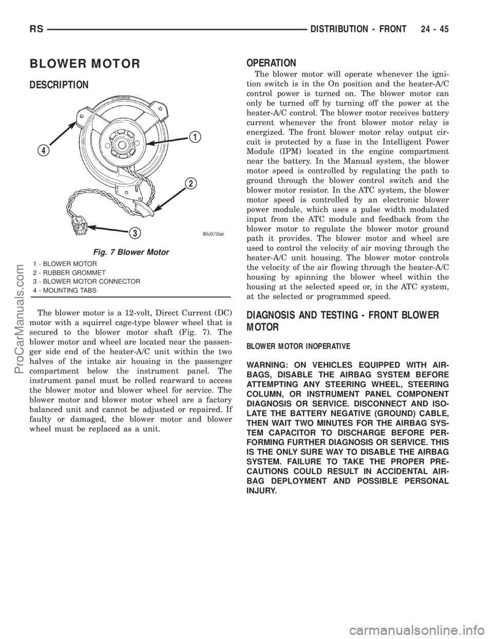
The blower motor is a 12-volt, Direct Current (DC)
motor with a squirrel cage-type blower wheel that is
secured to the blower motor shaft (Fig. 7). The
blower motor and wheel are located near the passen-
ger side end of the heater-A/C unit within the two
halves of the intake air housing in the passenger
compartment below the instrument panel. The
instrument panel must be rolled rearward to access
the blower motor and blower wheel for service. The
blower motor and blower motor wheel are a factory
balanced unit and cannot be adjusted or repaired. If
faulty or damaged, the blower motor and blower
wheel must be replaced as a unit.
OPERATION
The blower motor will operate whenever the igni-
tion switch is in the On position and the heater-A/C
control power is turned on. The blower motor can
only be turned off by turning off the power at the
heater-A/C control. The blower motor receives battery
current whenever the front blower motor relay is
energized. The front blower motor relay output cir-
cuit is protected by a fuse in the Intelligent Power
Module (IPM) located in the engine compartment
near the battery. In the Manual system, the blower
motor speed is controlled by regulating the path to
ground through the blower control switch and the
blower motor resistor. In the ATC system, the blower
motor speed is controlled by an electronic blower
power module, which uses a pulse width modulated
input from the ATC module and feedback from the
blower motor to regulate the blower motor ground
path it provides. The blower motor and wheel are
used to control the velocity of air moving through the
heater-A/C unit housing. The blower motor controls
the velocity of the air flowing through the heater-A/C
housing by spinning the blower wheel within the
housing at the selected speed or, in the ATC system,
at the selected or programmed speed.
DIAGNOSIS AND TESTING - FRONT BLOWER
MOTOR
BLOWER MOTOR INOPERATIVE
WARNING: ON VEHICLES EQUIPPED WITH AIR-
BAGS, DISABLE THE AIRBAG SYSTEM BEFORE
ATTEMPTING ANY STEERING WHEEL, STEERING
COLUMN, OR INSTRUMENT PANEL COMPONENT
DIAGNOSIS OR SERVICE. DISCONNECT AND ISO-
LATE THE BATTERY NEGATIVE (GROUND) CABLE,
THEN WAIT TWO MINUTES FOR THE AIRBAG SYS-
TEM CAPACITOR TO DISCHARGE BEFORE PER-
FORMING FURTHER DIAGNOSIS OR SERVICE. THIS
IS THE ONLY SURE WAY TO DISABLE THE AIRBAG
SYSTEM. FAILURE TO TAKE THE PROPER PRE-
CAUTIONS COULD RESULT IN ACCIDENTAL AIR-
BAG DEPLOYMENT AND POSSIBLE PERSONAL
INJURY.
Fig. 7 Blower Motor
1 - BLOWER MOTOR
2 - RUBBER GROMMET
3 - BLOWER MOTOR CONNECTOR
4 - MOUNTING TABS
RSDISTRIBUTION - FRONT24-45
ProCarManuals.com
Page 2213 of 2321
INSTALLATION
WARNING: ON VEHICLES EQUIPPED WITH AIR-
BAGS, DISABLE THE AIRBAG SYSTEM BEFORE
ATTEMPTING ANY STEERING WHEEL, STEERING
COLUMN, OR INSTRUMENT PANEL COMPONENT
DIAGNOSIS OR SERVICE. DISCONNECT AND ISO-
LATE THE BATTERY NEGATIVE (GROUND) CABLE,
THEN WAIT TWO MINUTES FOR THE AIRBAG SYS-
TEM CAPACITOR TO DISCHARGE BEFORE PER-
FORMING FURTHER DIAGNOSIS OR SERVICE. THIS
IS THE ONLY SURE WAY TO DISABLE THE AIRBAG
SYSTEM. FAILURE TO TAKE THE PROPER PRE-
CAUTIONS COULD RESULT IN ACCIDENTAL AIR-
BAG DEPLOYMENT AND POSSIBLE PERSONAL
INJURY.
(1) Position the defroster duct to the instrument
panel.
(2) Install the fasteners that secure the defroster
duct to the instrument panel armature.
(3) Reinstall the instrument panel in the vehicle.
(Refer to 23 - BODY/INSTRUMENT PANEL/IN-
STRUMENT PANEL ASSEMBLY - INSTALLA-
TION).
(4) Reconnect the battery negative cable.
DEMISTER DUCTS
REMOVAL
WARNING: ON VEHICLES EQUIPPED WITH AIR-
BAGS, DISABLE THE AIRBAG SYSTEM BEFORE
ATTEMPTING ANY STEERING WHEEL, STEERING
COLUMN, OR INSTRUMENT PANEL COMPONENT
DIAGNOSIS OR SERVICE. DISCONNECT AND ISO-
LATE THE BATTERY NEGATIVE (GROUND) CABLE,
THEN WAIT TWO MINUTES FOR THE AIRBAG SYS-
TEM CAPACITOR TO DISCHARGE BEFORE PER-
FORMING FURTHER DIAGNOSIS OR SERVICE. THIS
IS THE ONLY SURE WAY TO DISABLE THE AIRBAG
SYSTEM. FAILURE TO TAKE THE PROPER PRE-
CAUTIONS COULD RESULT IN ACCIDENTAL AIR-
BAG DEPLOYMENT AND POSSIBLE PERSONAL
INJURY.
(1) Disconnect and isolate the battery negative
cable.
(2) Remove the instrument panel from the vehicle.
(Refer to 23 - BODY/INSTRUMENT PANEL/IN-
STRUMENT PANEL ASSEMBLY - REMOVAL).
(3) Place the instrument panel face down on a
suitable work surface. Be certain to take the proper
precautions to protect the face of the instrument
panel from cosmetic damage.(4) Remove the fasteners that secure the demister
ducts to the instrument panel armature.
(5) Disengage the demister ducts from the demis-
ter outlets.
(6) Remove the demister ducts from the instru-
ment panel.
INSTALLATION
WARNING: ON VEHICLES EQUIPPED WITH AIR-
BAGS, DISABLE THE AIRBAG SYSTEM BEFORE
ATTEMPTING ANY STEERING WHEEL, STEERING
COLUMN, OR INSTRUMENT PANEL COMPONENT
DIAGNOSIS OR SERVICE. DISCONNECT AND ISO-
LATE THE BATTERY NEGATIVE (GROUND) CABLE,
THEN WAIT TWO MINUTES FOR THE AIRBAG SYS-
TEM CAPACITOR TO DISCHARGE BEFORE PER-
FORMING FURTHER DIAGNOSIS OR SERVICE. THIS
IS THE ONLY SURE WAY TO DISABLE THE AIRBAG
SYSTEM. FAILURE TO TAKE THE PROPER PRE-
CAUTIONS COULD RESULT IN ACCIDENTAL AIR-
BAG DEPLOYMENT AND POSSIBLE PERSONAL
INJURY.
(1) Position the demister ducts to the instrument
panel.
(2) Engage the demister ducts to the demister out-
lets.
(3) Install the fasteners that secure the demister
ducts to the instrument panel armature.
(4) Reinstall the instrument panel into the vehicle.
(Refer to 23 - BODY/INSTRUMENT PANEL/IN-
STRUMENT PANEL ASSEMBLY - INSTALLA-
TION).
(5) Reconnect the battery negative cable.
FLOOR DISTRIBUTION DUCTS
REMOVAL
(1) Roll back the carpet on the front floor from
under the instrument panel toward the rear of the
vehicle. (Refer to 23 - BODY/INTERIOR/CARPETS
AND FLOOR MATS - REMOVAL).
(2) Lift the center floor distribution duct upward
far enough to disengage its locator hole from the
weld stud on the front floor panel (Fig. 12).
(3) Pull the floor distribution duct assembly rear-
ward far enough to disengage the center floor distri-
bution duct from the outlet on the bottom of the
heater-A/C housing unit.
(4) Disassemble the right and/or left floor distribu-
tion ducts from the center floor distribution duct as
required.
24 - 50 DISTRIBUTION - FRONTRS
DEFROSTER DUCT (Continued)
ProCarManuals.com
Page 2219 of 2321
system control switch on the front heater-A/C control
is not in the Off position. The blower motor can only
be turned off by turning off the rear system at the
front heater-A/C control. The blower motor receives
battery current whenever the rear blower motor
relay is energized. The rear blower motor relay out-
put circuit is protected by a fuse in the Intelligent
Power Module (IPM) located in the engine compart-
ment near the battery. In the MTC system, the
blower motor speed is controlled by regulating the
path to ground through the blower control switch and
the blower motor resistor. In the ATC system, the
blower motor speed is controlled by an electronic
blower power module, which uses a pulse width mod-
ulated input from the ATC module and feedback from
the blower motor to regulate the blower motor
ground path it provides. The blower motor and wheel
are used to control the velocity of air moving through
the rear heater-A/C unit housing. The blower motor
controls the velocity of the air flowing through the
rear heater-A/C housing by spinning the blower
wheel within the housing at the selected speed or, in
the ATC system, at the selected or programmed
speed.
DIAGNOSIS AND TESTING - REAR BLOWER
MOTOR
BLOWER MOTOR INOPERATIVE
(1) Check the fuse (Fuse 12 - 25 ampere) in the
Intelligent Power Module (IPM). If OK, go to Step 2.
If not OK, repair the shorted circuit or component as
required and replace the faulty fuse.
(2) Turn the ignition switch to the On position. Be
certain that the rear heater-A/C control power is
turned on. Check for battery voltage at the fuse
(Fuse 12 - 25 ampere) in the IPM. If OK, go to Step
3. If not OK, proceed to diagnosis of the rear blower
motor relay. (Refer to 24 - HEATING & AIR CONDI-TIONING/CONTROLS - REAR/BLOWER MOTOR
RELAY - DIAGNOSIS AND TESTING).
(3) Turn the ignition switch to the Off position.
Disconnect and isolate the battery negative cable.
Disconnect the rear HVAC wire harness connector for
the rear blower motor resistor (Manual Temperature
Control) or the rear blower power module (Automatic
Temperature Control) from the resistor or module
connector receptacle. Reconnect the battery negative
cable. Turn the ignition switch to the On position. Be
certain that the rear heater-A/C control power is
turned on. Check for battery voltage at the fused
rear blower motor relay output circuit cavity of the
rear HVAC wire harness connector for the rear
blower motor resistor (MTC) or the rear blower
power module (ATC). If OK, go to Step 4. If not OK,
repair the open fused front blower motor relay output
circuit to the IPM as required.
(4) Turn the ignition switch to the Off position.
Disconnect and isolate the battery negative cable.
Disconnect the rear blower motor pigtail wire connec-
tor from the take out and connector of the rear
HVAC wire harness (MTC) or the connector recepta-
cle of the rear blower power module (ATC). Use
jumper wires to connect a battery and ground feeds
to the blower motor pigtail wire connector. The
blower motor should operate. If OK with MTC, pro-
ceed to diagnosis of the rear blower motor resistor.
(Refer to 24 - HEATING & AIR CONDITIONING/
CONTROLS - REAR/BLOWER MOTOR RESISTOR -
DIAGNOSIS AND TESTING). If OK with ATC, use a
DRBIII scan tool to diagnose the rear blower power
module. Refer to the appropriate diagnostic informa-
tion. If not OK with MTC or ATC, replace the faulty
rear blower motor.
BLOWER MOTOR NOISE OR VIBRATION
Refer to the Blower Motor Noise/Vibration Diagno-
sis chart (Fig. 4).
24 - 56 DISTRIBUTION - REARRS
BLOWER MOTOR (Continued)
ProCarManuals.com
Page 2222 of 2321
(2) Drain the engine cooling system. (Refer to 7 -
COOLING - STANDARD PROCEDURE - COOLING
SYSTEM DRAIN).
(3) Disconnect and isolate the battery negative
cable.
(4) Raise and support the vehicle.
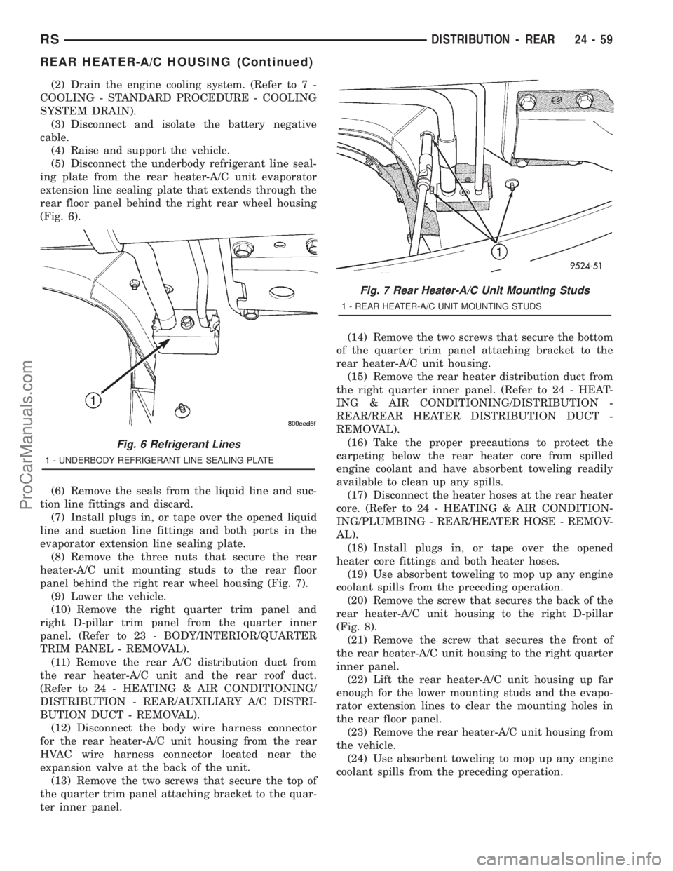
(5) Disconnect the underbody refrigerant line seal-
ing plate from the rear heater-A/C unit evaporator
extension line sealing plate that extends through the
rear floor panel behind the right rear wheel housing
(Fig. 6).
(6) Remove the seals from the liquid line and suc-
tion line fittings and discard.
(7) Install plugs in, or tape over the opened liquid
line and suction line fittings and both ports in the
evaporator extension line sealing plate.
(8) Remove the three nuts that secure the rear
heater-A/C unit mounting studs to the rear floor
panel behind the right rear wheel housing (Fig. 7).
(9) Lower the vehicle.
(10) Remove the right quarter trim panel and
right D-pillar trim panel from the quarter inner
panel. (Refer to 23 - BODY/INTERIOR/QUARTER
TRIM PANEL - REMOVAL).
(11) Remove the rear A/C distribution duct from
the rear heater-A/C unit and the rear roof duct.
(Refer to 24 - HEATING & AIR CONDITIONING/
DISTRIBUTION - REAR/AUXILIARY A/C DISTRI-
BUTION DUCT - REMOVAL).
(12) Disconnect the body wire harness connector
for the rear heater-A/C unit housing from the rear
HVAC wire harness connector located near the
expansion valve at the back of the unit.
(13) Remove the two screws that secure the top of
the quarter trim panel attaching bracket to the quar-
ter inner panel.(14) Remove the two screws that secure the bottom
of the quarter trim panel attaching bracket to the
rear heater-A/C unit housing.
(15) Remove the rear heater distribution duct from
the right quarter inner panel. (Refer to 24 - HEAT-
ING & AIR CONDITIONING/DISTRIBUTION -
REAR/REAR HEATER DISTRIBUTION DUCT -
REMOVAL).
(16) Take the proper precautions to protect the
carpeting below the rear heater core from spilled
engine coolant and have absorbent toweling readily
available to clean up any spills.
(17) Disconnect the heater hoses at the rear heater
core. (Refer to 24 - HEATING & AIR CONDITION-
ING/PLUMBING - REAR/HEATER HOSE - REMOV-
AL).
(18) Install plugs in, or tape over the opened
heater core fittings and both heater hoses.
(19) Use absorbent toweling to mop up any engine
coolant spills from the preceding operation.
(20) Remove the screw that secures the back of the
rear heater-A/C unit housing to the right D-pillar
(Fig. 8).
(21) Remove the screw that secures the front of
the rear heater-A/C unit housing to the right quarter
inner panel.
(22) Lift the rear heater-A/C unit housing up far
enough for the lower mounting studs and the evapo-
rator extension lines to clear the mounting holes in
the rear floor panel.
(23) Remove the rear heater-A/C unit housing from
the vehicle.
(24) Use absorbent toweling to mop up any engine
coolant spills from the preceding operation.
Fig. 6 Refrigerant Lines
1 - UNDERBODY REFRIGERANT LINE SEALING PLATE
Fig. 7 Rear Heater-A/C Unit Mounting Studs
1 - REAR HEATER-A/C UNIT MOUNTING STUDS
RSDISTRIBUTION - REAR24-59
REAR HEATER-A/C HOUSING (Continued)
ProCarManuals.com
Page 2223 of 2321
INSTALLATION
NOTE: If the rear heater core or the rear heater-A/C
housing have been removed from the vehicle for
service, the rear heater core may be pre-filled with
the proper engine coolant mixture prior to recon-
necting the heater hoses to the heater core hose fit-
tings. (Refer to 24 - HEATING & AIR CONDITIONING/
PLUMBING - REAR/HEATER CORE - STANDARD
PROCEDURE - HEATER CORE FILLING).
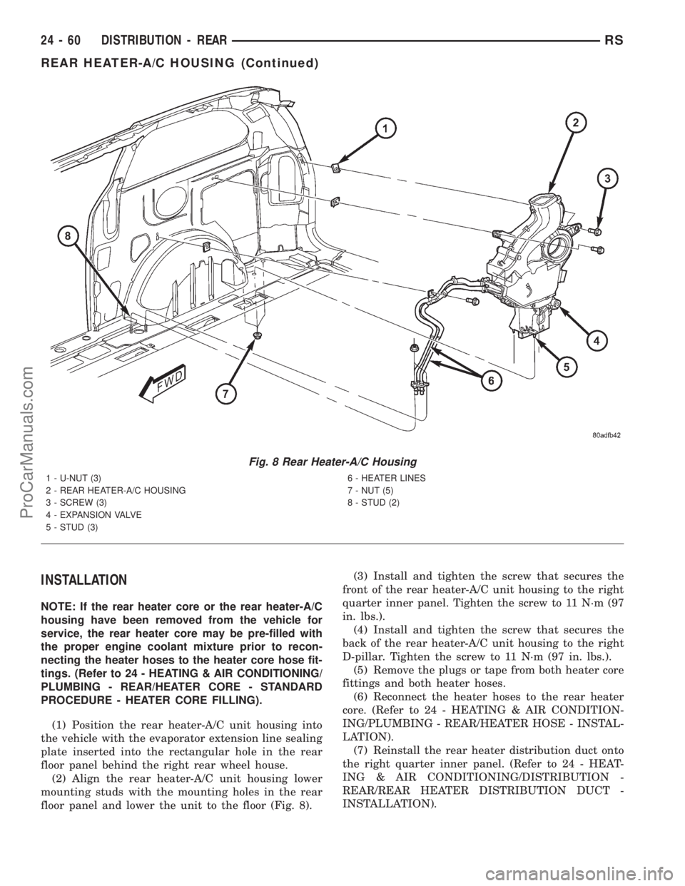
(1) Position the rear heater-A/C unit housing into
the vehicle with the evaporator extension line sealing
plate inserted into the rectangular hole in the rear
floor panel behind the right rear wheel house.
(2) Align the rear heater-A/C unit housing lower
mounting studs with the mounting holes in the rear
floor panel and lower the unit to the floor (Fig. 8).(3) Install and tighten the screw that secures the
front of the rear heater-A/C unit housing to the right
quarter inner panel. Tighten the screw to 11 N´m (97
in. lbs.).
(4) Install and tighten the screw that secures the
back of the rear heater-A/C unit housing to the right
D-pillar. Tighten the screw to 11 N´m (97 in. lbs.).
(5) Remove the plugs or tape from both heater core
fittings and both heater hoses.
(6) Reconnect the heater hoses to the rear heater
core. (Refer to 24 - HEATING & AIR CONDITION-
ING/PLUMBING - REAR/HEATER HOSE - INSTAL-
LATION).
(7) Reinstall the rear heater distribution duct onto
the right quarter inner panel. (Refer to 24 - HEAT-
ING & AIR CONDITIONING/DISTRIBUTION -
REAR/REAR HEATER DISTRIBUTION DUCT -
INSTALLATION).
Fig. 8 Rear Heater-A/C Housing
1 - U-NUT (3)
2 - REAR HEATER-A/C HOUSING
3 - SCREW (3)
4 - EXPANSION VALVE
5 - STUD (3)6 - HEATER LINES
7 - NUT (5)
8 - STUD (2)
24 - 60 DISTRIBUTION - REARRS
REAR HEATER-A/C HOUSING (Continued)
ProCarManuals.com
Page 2224 of 2321
(8) Install and tighten the two screws that secure
the bottom of the quarter trim panel attaching
bracket to the rear heater-A/C unit housing. Tighten
the screws to 1.7 N´m (15 in. lbs.).
(9) Install and tighten the two screws that secure
the top of the quarter trim panel attaching bracket to
the quarter inner panel.
(10) Reconnect the body wire harness connector for
the rear heater-A/C unit housing to the rear HVAC
wire harness connector located near the expansion
valve at the back of the unit.
(11) Reinstall the auxiliary A/C distribution duct
onto the rear heater-A/C unit and the rear roof duct.
(Refer to 24 - HEATING & AIR CONDITIONING/
DISTRIBUTION - REAR/AUXILIARY A/C DISTRI-
BUTION DUCT - INSTALLATION).
(12) Reinstall the right quarter trim panel and
right D-pillar trim panel onto the quarter inner
panel. (Refer to 23 - BODY/INTERIOR/QUARTER
TRIM PANEL - INSTALLATION).
(13) Raise and support the vehicle.
(14) Install and tighten the three nuts that secure
the rear heater-A/C unit mounting studs to the rear
floor panel behind the right rear wheel housing (Fig.
7). Tighten the nuts to 9 N´m (80 in. lbs.).
(15) Remove the tape or plugs from the underbody
liquid line and suction line fittings and both ports in
the rear heater-A/C unit evaporator extension line
sealing plate that extends through the rear floor
panel behind the right rear wheel housing.
(16) Lubricate new rubber O-ring seals with clean
refrigerant oil and install them on the liquid line and
suction line fittings.
(17) Reconnect the underbody refrigerant line seal-
ing plate to the evaporator extension line sealing
plate (Fig. 6).
(18) Install and tighten the screw that secures the
underbody refrigerant line sealing plate to the evap-
orator extension line sealing plate. Tighten the screw
to 23 N´m (17 ft. lbs.).
(19) Lower the vehicle.
(20) Reconnect the battery negative cable.
(21) Refill the engine cooling system. (Refer to 7 -
COOLING - STANDARD PROCEDURE - COOLING
SYSTEM REFILL).
(22) Evacuate the refrigerant system. (Refer to 24
- HEATING & AIR CONDITIONING/PLUMBING -
FRONT/REFRIGERANT - STANDARD PROCE-
DURE - REFRIGERANT SYSTEM EVACUATE).
(23) Charge the refrigerant system. (Refer to 24 -
HEATING & AIR CONDITIONING/PLUMBING -
FRONT/REFRIGERANT - STANDARD PROCE-
DURE - REFRIGERANT SYSTEM CHARGE).REAR HEATER DISTRIBUTION
DUCT
REMOVAL
(1) Remove the trim from the right quarter inner
panel. (Refer to 23 - BODY/INTERIOR/RIGHT
QUARTER TRIM PANEL - REMOVAL).
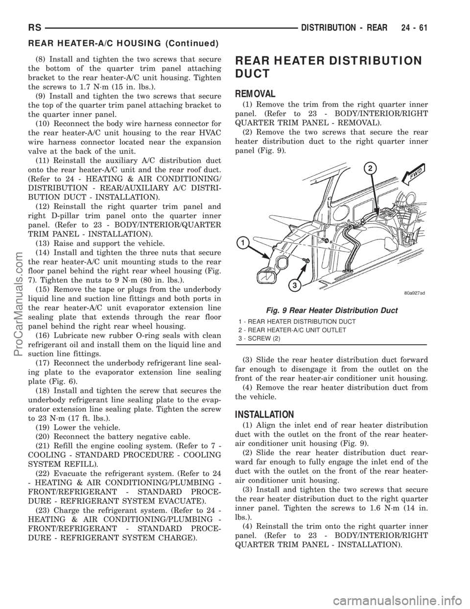
(2) Remove the two screws that secure the rear
heater distribution duct to the right quarter inner
panel (Fig. 9).
(3) Slide the rear heater distribution duct forward
far enough to disengage it from the outlet on the
front of the rear heater-air conditioner unit housing.
(4) Remove the rear heater distribution duct from
the vehicle.
INSTALLATION
(1) Align the inlet end of rear heater distribution
duct with the outlet on the front of the rear heater-
air conditioner unit housing (Fig. 9).
(2) Slide the rear heater distribution duct rear-
ward far enough to fully engage the inlet end of the
duct with the outlet on the front of the rear heater-
air conditioner unit housing.
(3) Install and tighten the two screws that secure
the rear heater distribution duct to the right quarter
inner panel. Tighten the screws to 1.6 N´m (14 in.
lbs.).
(4) Reinstall the trim onto the right quarter inner
panel. (Refer to 23 - BODY/INTERIOR/RIGHT
QUARTER TRIM PANEL - INSTALLATION).
Fig. 9 Rear Heater Distribution Duct
1 - REAR HEATER DISTRIBUTION DUCT
2 - REAR HEATER-A/C UNIT OUTLET
3 - SCREW (2)
RSDISTRIBUTION - REAR24-61
REAR HEATER-A/C HOUSING (Continued)
ProCarManuals.com
Page 2238 of 2321
HEATING & AIR CONDITIONING - DIAGNOSIS
AND TESTING - A/C PERFORMANCE TEST).
Remove all test equipment before returning the vehi-
cle to service.
REMOVAL
WARNING: REFER TO THE APPLICABLE WARN-
INGS AND CAUTIONS FOR THIS SYSTEM BEFORE
PERFORMING THE FOLLOWING OPERATION.
(Refer to 24 - HEATING & AIR CONDITIONING/
PLUMBING - FRONT - WARNING - A/C PLUMBING)
and (Refer to 24 - HEATING & AIR CONDITIONING/
PLUMBING - FRONT - CAUTION - A/C PLUMBING).
(1) Recover the refrigerant from the refrigerant
system. (Refer to 24 - HEATING & AIR CONDI-
TIONING/PLUMBING - FRONT/REFRIGERANT -
STANDARD PROCEDURE - REFRIGERANT
RECOVERY).
(2) Disconnect and isolate the battery negative
cable.
(3) Remove the air cleaner housing from the right
side of the engine compartment.
(4) Disconnect the drain tube from the wiper mod-
ule drain on the right side of the engine compart-
ment.
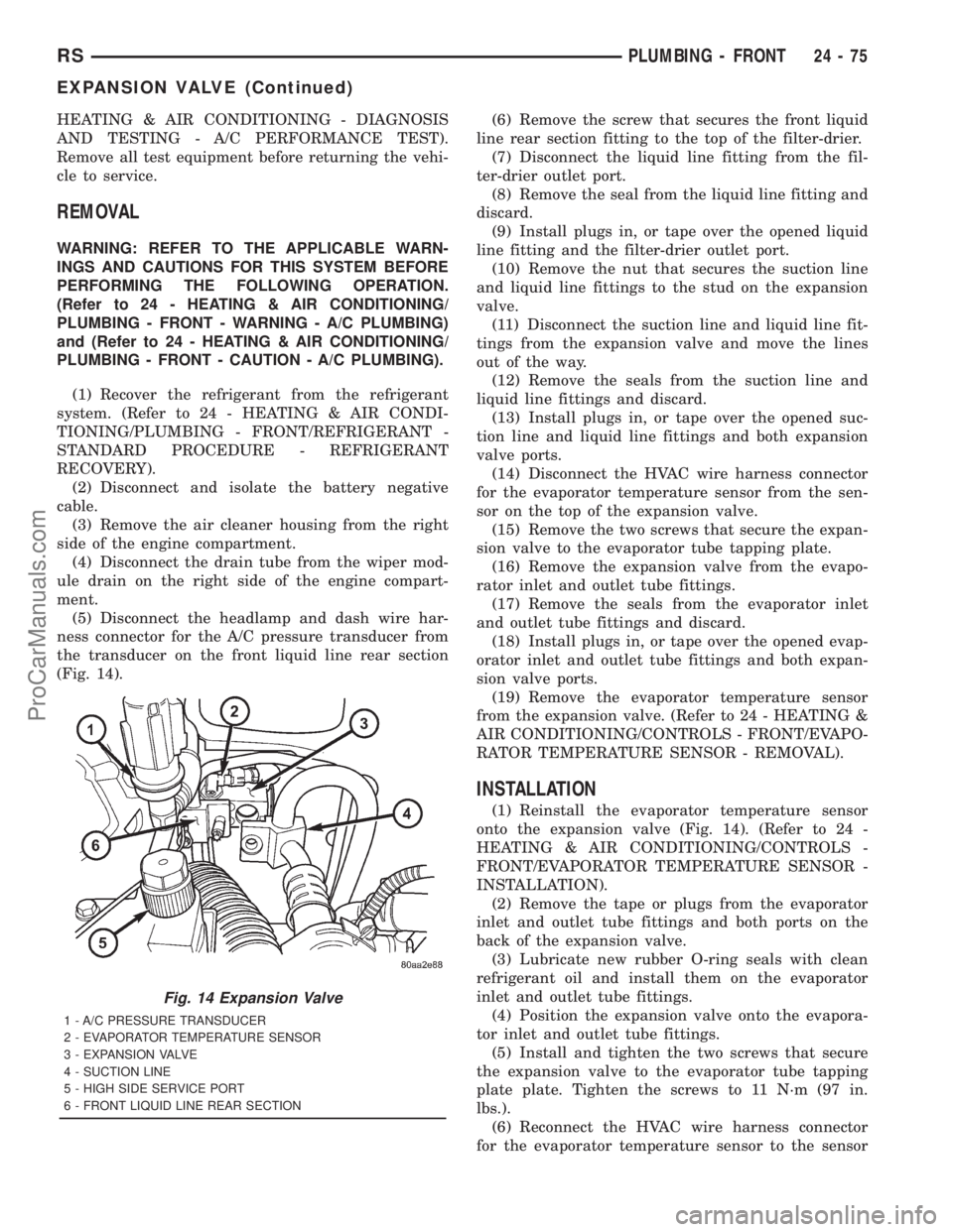
(5) Disconnect the headlamp and dash wire har-
ness connector for the A/C pressure transducer from
the transducer on the front liquid line rear section
(Fig. 14).(6) Remove the screw that secures the front liquid
line rear section fitting to the top of the filter-drier.
(7) Disconnect the liquid line fitting from the fil-
ter-drier outlet port.
(8) Remove the seal from the liquid line fitting and
discard.
(9) Install plugs in, or tape over the opened liquid
line fitting and the filter-drier outlet port.
(10) Remove the nut that secures the suction line
and liquid line fittings to the stud on the expansion
valve.
(11) Disconnect the suction line and liquid line fit-
tings from the expansion valve and move the lines
out of the way.
(12) Remove the seals from the suction line and
liquid line fittings and discard.
(13) Install plugs in, or tape over the opened suc-
tion line and liquid line fittings and both expansion
valve ports.
(14) Disconnect the HVAC wire harness connector
for the evaporator temperature sensor from the sen-
sor on the top of the expansion valve.
(15) Remove the two screws that secure the expan-
sion valve to the evaporator tube tapping plate.
(16) Remove the expansion valve from the evapo-
rator inlet and outlet tube fittings.
(17) Remove the seals from the evaporator inlet
and outlet tube fittings and discard.
(18) Install plugs in, or tape over the opened evap-
orator inlet and outlet tube fittings and both expan-
sion valve ports.
(19) Remove the evaporator temperature sensor
from the expansion valve. (Refer to 24 - HEATING &
AIR CONDITIONING/CONTROLS - FRONT/EVAPO-
RATOR TEMPERATURE SENSOR - REMOVAL).
INSTALLATION
(1) Reinstall the evaporator temperature sensor
onto the expansion valve (Fig. 14). (Refer to 24 -
HEATING & AIR CONDITIONING/CONTROLS -
FRONT/EVAPORATOR TEMPERATURE SENSOR -
INSTALLATION).
(2) Remove the tape or plugs from the evaporator
inlet and outlet tube fittings and both ports on the
back of the expansion valve.
(3) Lubricate new rubber O-ring seals with clean
refrigerant oil and install them on the evaporator
inlet and outlet tube fittings.
(4) Position the expansion valve onto the evapora-
tor inlet and outlet tube fittings.
(5) Install and tighten the two screws that secure
the expansion valve to the evaporator tube tapping
plate plate. Tighten the screws to 11 N´m (97 in.
lbs.).
(6) Reconnect the HVAC wire harness connector
for the evaporator temperature sensor to the sensor
Fig. 14 Expansion Valve
1 - A/C PRESSURE TRANSDUCER
2 - EVAPORATOR TEMPERATURE SENSOR
3 - EXPANSION VALVE
4 - SUCTION LINE
5 - HIGH SIDE SERVICE PORT
6 - FRONT LIQUID LINE REAR SECTION
RSPLUMBING - FRONT24-75
EXPANSION VALVE (Continued)
ProCarManuals.com
Page 2244 of 2321
CAUTION:
When removing the heater hose from the heater
core or supply and return tube nipples, DO NOT
apply excessive pressure. Excessive pressure may
damage or deform the nipples and/or the heater
core causing an engine coolant leak.(3) After the clamp has been moved, grasp the end
of the hose firmly and carefully twist the hose back
and forth while pulling it away from the barbed end
of the nipple. Repeat this procedure at the opposite
end of the hose being removed. If this procedure is
not successful in removing the hose from the nipple,
carefully make a parallel cut through the hose where
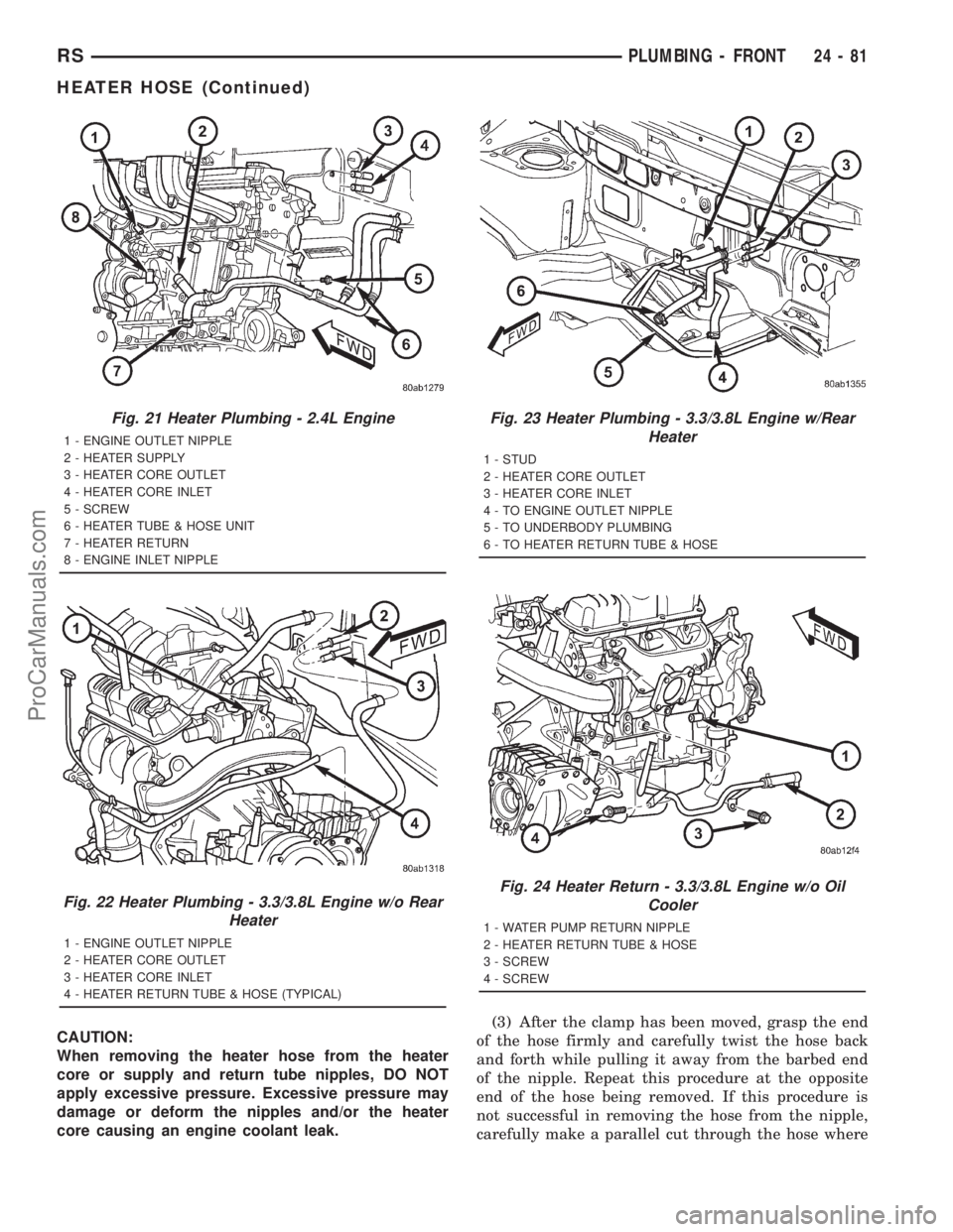
Fig. 21 Heater Plumbing - 2.4L Engine
1 - ENGINE OUTLET NIPPLE
2 - HEATER SUPPLY
3 - HEATER CORE OUTLET
4 - HEATER CORE INLET
5 - SCREW
6 - HEATER TUBE & HOSE UNIT
7 - HEATER RETURN
8 - ENGINE INLET NIPPLE
Fig. 22 Heater Plumbing - 3.3/3.8L Engine w/o Rear
Heater
1 - ENGINE OUTLET NIPPLE
2 - HEATER CORE OUTLET
3 - HEATER CORE INLET
4 - HEATER RETURN TUBE & HOSE (TYPICAL)
Fig. 23 Heater Plumbing - 3.3/3.8L Engine w/Rear
Heater
1 - STUD
2 - HEATER CORE OUTLET
3 - HEATER CORE INLET
4 - TO ENGINE OUTLET NIPPLE
5 - TO UNDERBODY PLUMBING
6 - TO HEATER RETURN TUBE & HOSE
Fig. 24 Heater Return - 3.3/3.8L Engine w/o Oil
Cooler
1 - WATER PUMP RETURN NIPPLE
2 - HEATER RETURN TUBE & HOSE
3 - SCREW
4 - SCREW
RSPLUMBING - FRONT24-81
HEATER HOSE (Continued)
ProCarManuals.com