2001 DODGE TOWN AND COUNTRY Window fuse
[x] Cancel search: Window fusePage 351 of 2321
ANTENNA MODULE
DESCRIPTION
The antenna module is an electromagnetic circuit
component designed to capture and enhance RF
(Radio Frequency) signals in both the AM and FM
broadcast bands. The antenna module is mounted to
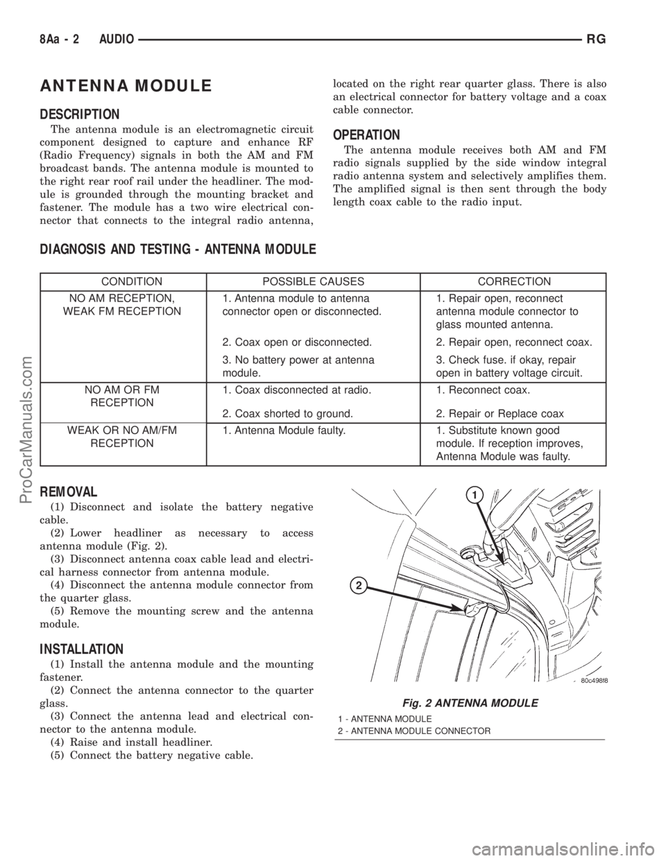
the right rear roof rail under the headliner. The mod-
ule is grounded through the mounting bracket and
fastener. The module has a two wire electrical con-
nector that connects to the integral radio antenna,located on the right rear quarter glass. There is also
an electrical connector for battery voltage and a coax
cable connector.OPERATION
The antenna module receives both AM and FM
radio signals supplied by the side window integral
radio antenna system and selectively amplifies them.
The amplified signal is then sent through the body
length coax cable to the radio input.
DIAGNOSIS AND TESTING - ANTENNA MODULE
CONDITION POSSIBLE CAUSES CORRECTION
NO AM RECEPTION,
WEAK FM RECEPTION1. Antenna module to antenna
connector open or disconnected.1. Repair open, reconnect
antenna module connector to
glass mounted antenna.
2. Coax open or disconnected. 2. Repair open, reconnect coax.
3. No battery power at antenna
module.3. Check fuse. if okay, repair
open in battery voltage circuit.
NO AM OR FM
RECEPTION1. Coax disconnected at radio. 1. Reconnect coax.
2. Coax shorted to ground. 2. Repair or Replace coax
WEAK OR NO AM/FM
RECEPTION1. Antenna Module faulty. 1. Substitute known good
module. If reception improves,
Antenna Module was faulty.
REMOVAL
(1) Disconnect and isolate the battery negative
cable.
(2) Lower headliner as necessary to access
antenna module (Fig. 2).
(3) Disconnect antenna coax cable lead and electri-
cal harness connector from antenna module.
(4) Disconnect the antenna module connector from
the quarter glass.
(5) Remove the mounting screw and the antenna
module.
INSTALLATION
(1) Install the antenna module and the mounting
fastener.
(2) Connect the antenna connector to the quarter
glass.
(3) Connect the antenna lead and electrical con-
nector to the antenna module.
(4) Raise and install headliner.
(5) Connect the battery negative cable.
Fig. 2 ANTENNA MODULE
1 - ANTENNA MODULE
2 - ANTENNA MODULE CONNECTOR
8Aa - 2 AUDIORG
ProCarManuals.com
Page 431 of 2321

OPERATION
The Rear Window Defogger (Fig. 1) system consists
of two vertical bus bars linked by a series of grid
lines on the inside surface of the rear window. The
electrical circuit consists of the rear defogger switch
in the HVAC control assembly and a relay with timer
switch to turn OFF the system after ten minutes.
The main feed circuit is protected by fuse 13 (40
amp) in the Power Distribution Center (PDC) which
is integrated as a unit call Integrated Power Module
(IPM). The rear defogger switch and relay also acti-
vates the heated power side view mirrors and heated
windshield wiper de-icer. The heated windshield
wiper de-icer is powered by the RUN/ACC relay in
the IPM and feed thru fuse #11 (20 amp) in the PDC.
The heated mirror circuit is protected by a non-servi-
cable Positive Temperature Coefficient (PTC) located
inside the PDC. The heated windshield wiper de-icer
circuit is protected by fuse 11 (20 amp) in the PDC.
The Heated Windshield Wiper Deicer is also acti-
vated when the DEFROST mode is selected on the
HVAC. In the DEFROST mode the rear defogger
relay/timer is bypassed, the heated windshield wiper
de-icer will stay ON until the another mode is
selected. For circuit information and component loca-
tion refer to appropriate section for Wiring Diagrams.
CAUTION:
Since grid lines can be damaged or scraped off
with sharp instruments, care should be taken in
cleaning the glass or removing foreign materials,
decals or stickers. Normal glass cleaning solvents
or hot water used with rags or toweling is recom-
mended.
DEFOGGER RELAY
DESCRIPTION
There is no heated glass relay it is integrated into
the (E.B.L) relay that is located in the IPM in the
engine compartment.
REAR WINDOW DEFOGGER
GRID
STANDARD PROCEDURE - GRID LINE
REPAIR-REAR
For Grid repair procedure for the rear window
defogger (Refer to 8 - ELECTRICAL/HEATED
GLASS/WINDSHIELD GRID - STANDARD PROCE-
DURE).
REAR WINDOW DEFOGGER
SWITCH
DESCRIPTION
The rear window defogger switch is integrated into
the HVAC control panel assembly (Fig. 3)
OPERATION
A LED indicator will illuminate when the switch is
activated. The switch energizes the HVAC control
assembly when it requests the Front Control Module
(FCM) to activate the rear window defogger relay.
The relay controls the current to flow to the grids of
the rear window defogger, heated power side view
mirrors and the heated windshield wiper de-icer. The
defogger relay will be on for approximately 10 min-
utes or until the control switch or ignition is turned
off.
Fig. 3 HVAC CONTROL PANEL
1 - Trim Bezel
2 - ACT Sensor
3 - A/C Request Switch
4 - Rear Window Defogger/Heated Mirrors Switch Combo
5 - Front Window Defroster Mode Selector
8G - 2 HEATED GLASSRS
HEATED GLASS (Continued)
ProCarManuals.com
Page 432 of 2321
WINDSHIELD GRID
DIAGNOSIS AND TESTING - SYSTEM TEST
Electrically heated rear window defogger or the
heated windshield wiper deicer operation can be
checked on the vehicle in the following manner:
(1) Turn the ignition switch to the ON position.
(2) Using a ammeter on the battery, turn the rear
defogger control switch to the ON position, a distinct
increase in amperage draw should be noted.
(3) The rear window defogger or the heated wind-
shield wiper deicer operation can be checked by feel-
ing the glass. A distinct difference in temperature
between the grid lines and adjacent clear glass can
be detected in 3 to 4 minutes of operation.
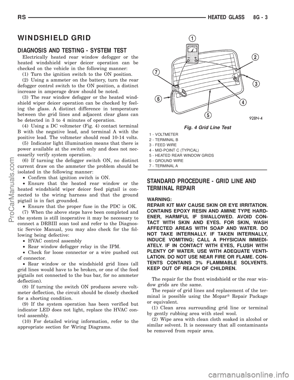
(4) Using a DC voltmeter (Fig. 4) contact terminal
B with the negative lead, and terminal A with the
positive lead. The voltmeter should read 10-14 volts.
(5) Indicator light illumination means that there is
power available at the switch only and does not nec-
essarily verify system operation.
(6) If turning the defogger switch ON, no distinct
current draw on the ammeter the problem should be
isolated in the following manner:
²Confirm that ignition switch is ON.
²Ensure that the heated rear window or the
heated windshield wiper deicer feed pigtail is con-
nected to the wiring harness and that the ground
pigtail is in fact grounded.
²Ensure that the proper fuse in the PDC is OK.
(7) When the above steps have been completed and
the system is still inoperative it may be necessary to
connect a DRBIII scan tool and refer to the Diagnos-
tic Service Manual, you may also check for the fol-
lowing being defective:
²HVAC control assembly
²Rear window defogger relay in the IPM.
²Check for loose connector or a wire pushed out
of connector.
²Rear window or the windshield grid lines (all
grid lines would have to be broken, or one of the feed
pigtails not connected to the bus bar, for no ammeter
deflection).
(8) If turning the switch ON produces severe volt-
meter deflection, the circuit should be closely checked
for a shorting condition.
(9) If the system operation has been verified but
indicator LED does not light, replace the HVAC con-
trol assembly.
(10) For detailed wiring information, refer to the
appropriate section for Wiring Diagrams.
STANDARD PROCEDURE - GRID LINE AND
TERMINAL REPAIR
WARNING:
REPAIR KIT MAY CAUSE SKIN OR EYE IRRITATION.
CONTAINS EPOXY RESIN AND AMINE TYPE HARD-
ENER, HARMFUL IF SWALLOWED. AVOID CON-
TACT WITH SKIN AND EYES. FOR SKIN, WASH
AFFECTED AREAS WITH SOAP AND WATER. DO
NOT TAKE INTERNALLY. IF TAKEN INTERNALLY,
INDUCE VOMITING; CALL A PHYSICIAN IMMEDI-
ATELY. IF IN CONTACT WITH EYES, FLUSH WITH
PLENTY OF WATER. USE WITH ADEQUATE VENTI-
LATION. DO NOT USE NEAR FIRE OR FLAME. CON-
TENTS CONTAINS 3% FLAMMABLE SOLVENTS.
KEEP OUT OF REACH OF CHILDREN.
The repair for the front windshield or the rear win-
dow grids are the same.
The repair of grid lines and replacement of the ter-
minal is possible using the MopartRepair Package
or equivalent.
(1) Clean area surrounding grid line or terminal
by gently rubbing area with steel wool.
(2) Wipe area with clean cloth soaked in alcohol or
similar solvent. It is necessary that all contaminants
be removed from repair area.
Fig. 4 Grid Line Test
1 - VOLTMETER
2 - TERMINAL B
3 - FEED WIRE
4 - MID-POINT C (TYPICAL)
5 - HEATED REAR WINDOW GRIDS
6 - GROUND WIRE
7 - TERMINAL A
RSHEATED GLASS8G-3
ProCarManuals.com
Page 434 of 2321

HEATED MIRRORS
TABLE OF CONTENTS
page page
HEATED MIRRORS
DESCRIPTION............................5
OPERATION.............................5
DIAGNOSIS AND TESTING..................5
HEATED MIRROR TEST...................5
MIRROR SWITCH
DESCRIPTION............................5OPERATION.............................5
HEATED MIRROR GRID
STANDARD PROCEDURE...................6
HEATED MIRROR.......................6
RELAY
DESCRIPTION............................6
HEATED MIRRORS
DESCRIPTION
Heated mirrors are available on models with
Power Mirrors and Rear Window Defogger only.
OPERATION
The heated mirror is controlled by the rear window
defogger switch. The heated mirror is ON when the
rear window defogger is ON (Fig. 1)
DIAGNOSIS AND TESING - HEATED MIRROR
TEST
Heated mirrors are available on models with
Power Mirrors and Rear Window Defogger only. The
heated mirror is controlled by the rear window defog-
ger switch. The heated mirror is ON when the rear
window defogger is ON.
(1) The mirror glass should be warm to the touch.
(2) If not, check the 20 amp fuse (11) in the Power
Distribution Center (PDC) part of the Integrated
Power Module (IPM) in the engine compartment.
(3) Test voltage at rear window defogger switch.
²If no voltage repair wire.
²Remove mirror glass and test the wires for con-
tinuity. If no continuity repair wires.
²If wires are OK, replace mirror glass.
²To test defogger switch refer to the appropriate
section in Electrical.
MIRROR SWITCH
DESCRIPTION
The heated mirror switch is integrated into the
rear window defogger switch located in the HVAC
control panel (Fig. 1)
OPERATION
A LED indicator will illuminate when the switch is
activated. The switch energizes the HVAC control
assembly when it requests the Front Control Module
(FCM) to activate the rear window defogger relay.
The relay controls the current to flow to the grids of
the rear window defogger, heated power side view
mirrors and the heated windshield wiper de-icer. The
defogger relay will be on for approximately 10 min-
utes or until the control switch or ignition is turned
off.
Fig. 1 HVAC CONTROL PANEL
1 - Trim Bezel
2 - ACT Sensor
3 - A/C Request Switch
4 - Rear Window Defogger/Heated Mirrors Switch Combo
5 - Front Window Defroster Mode Selector
RSHEATED MIRRORS8G-5
ProCarManuals.com
Page 437 of 2321

²Remote Keyless Entry Module (RKE)- Refer
toRemote Keyless Entry Modulein Power Locks
for more information.
²Electronic Vehicle Information Center
(EVIC)- Refer toElectronic Vehicle Information
Centerin Overhead Console for more information.
²Heated Seat Module (HSM)- Refer toHeated
Seat Modulein Electronic Control Modules for more
information.
²Memory Heated Seat Module (MHSM)-If
the vehicle is equipped with the Memory System,
refer toMemory Seat Mirror Module (MSMM)in
Electronic Control Modules for more information.
Refer toWiring Diagramsfor complete circuit
diagrams. Following are general descriptions of the
major components in the heated seat system.
OPERATION
The heated seat system will only operate when the
ignition switch is in the On position, and the surface
temperature at the front seat heating element sen-
sors is below the designed temperature set points of
the system. The heated seat system will not operate
in ambient temperatures greater than about 41É C
(105É F). The front seat heating elements and sensors
are hard wired to the Heated Seat Module (HSM) or
the Memory Heated Seat Module (MHSM).
The heated seat switches are hard wired to the
Body Control Module (BCM). The BCM monitors the
heated seat switch inputs, then sends heated seat
switch status messages to the HSM or MHSM over
the Programmable Communications Interface J1850
(PCI) data bus. The HSM or MHSM contains the con-
trol logic for the heated seat system. The HSM or
MHSM responds to the heated seat switch status
messages, ignition switch status messages, and the
front seat heating element sensor inputs by control-
ling the output to the front seat heating elements
through integral solid-state relays.
When a seat heater is turned on, the sensor
located on the seat cushion electric heater element
provides the HSM or MHSM with an input indicating
the surface temperature of the seat cushion. If the
surface temperature input is below the temperature
set point for the selected Low or High heated seat
switch position, the HSM or MHSM energizes the
integral solid-state relay, which supplies battery cur-
rent to the heating elements in the seat cushion and
back. When the sensor input indicates the correct
temperature set point has been achieved, the HSM or
MHSM de-energizes the solid-state relay. The HSM
or MHSM will continue to cycle the solid-state relay
as needed to maintain the temperature set point.
The HSM or MHSM and the seat heater elements
operate on non-switched battery current supplied
through the power seat fuse in the intelligent powermodule. However, the HSM or MHSM will automati-
cally turn off the heating elements if it detects an
open in the sensor circuit, a short in the heating ele-
ment circuit causing an excessive current draw, or
when the ignition switch is turned to the Off posi-
tion.
See the owner's manual in the vehicle glove box for
more information on the features, use and operation
of the heated seat system.
DRIVER HEATED SEAT
SWITCH
DESCRIPTION
The heated seat switches are mounted in the
instrument panel center bezel (Fig. 2). The two three-
position rocker-type switches, one switch for each
front seat, are incorporated into one large switch
assembly that also includes the hazzard, rear window
wiper and washer switches. The heated seat switches
provide a resistor multiplexed signal to the Body
Control Module (BCM) through separate hard wired
circuits. Each switch has an Off, Low, and High posi-
tion so that both the driver and the front seat pas-
senger can select a preferred seat heating mode.
Each switch has two Light-Emitting Diodes (LED)
which light to indicate that the heater for the seat is
turned on.
The heated seat switches and their LEDs cannot
be repaired. If either switch or LED is faulty or dam-
aged, the entire switch assembly must be replaced.
Fig. 2 HEATED SEAT SWITCHES
8G - 8 HEATED SEAT SYSTEMRS
HEATED SEAT SYSTEM (Continued)
ProCarManuals.com
Page 534 of 2321

NOTE: It may be possible to generate Sliding Door
Diagnostic Trouble Codes during normal power
sliding door operation. Refer to the Body Diagnos-
tic Manual for a complete list of diagnostic routines.
For additional information, (Refer to 8 - ELECTRI-
CAL/POWER DOORS - OPERATION) . For a com-
plete power sliding door system wiring schematic,
refer to Wiring Diagrams. For power sliding door sys-
tem operation instructions, refer to the vehicle owner
manual.
WARNING: BE CERTAIN TO READ ALL WARNINGS
AND CAUTIONS IN POWER SLIDING DOOR OPER-
ATION BEFORE ATTEMPTING ANY SERVICE OF
POWER SLIDING DOOR SYSTEM OR COMPO-
NENTS.
OPERATION
With the push of a power sliding door open/close
command switch (key fob, overhead console or B-pil-
lar mounted) a signal is sent out to the Body Control
Module (BCM). The BCM then sends a signal out on
the PCI Data Bus circuit (J1850) to the power sliding
door module. The power sliding door module then
signals the power sliding door latch to release the
door to the unlatched and movable position. The
motor then starts an open cycle.
During the door open cycle, if the power sliding
door module detects sufficient resistance to door
travel, such as an obstruction in the door's path, the
power sliding door module will immediately stop door
movement and reverse door travel to the full open orclosed position. The ability for the power sliding door
module to detect resistance to door travel is accom-
plished by hall effect sensors and the door motor
speed.
The power sliding door control module has the abil-
ity to learn. Anytime a door is opened or closed using
the power sliding door system the module learns
from its cycle. If a replacement power sliding door
component is installed or a door adjustment is made,
the module must re-learn the effort required to open
or close the door. A learn cycle can be performed with
a Diagnostic Scan Tool, such as the DRB IIIt, or with
a complete cycle of the door, using any one of the
command switches. Refer to Standard Procedures in
this section for detailed instructions.
The power sliding door system is designed with a
number of system inhibitors. These inhibitors are
necessary for safety and/or feasibility of the power
sliding door system. See the power sliding door sys-
tem inhibitors noted below:
POWER SLIDING DOOR SYSTEM INHIBITORS
²The power sliding door must be in thefullopen
or closed position in order for the power sliding door
system to start a cycle. If the door is not in this posi-
tion (based on the input from the full open, pawl or
ratchet switches) the door control module will not
respond to command switch inputs.
²The vehicles transmission must be inpark or
neutralin order for the power sliding door system to
start a cycle.
²The vehicles child lockout switch must be in the
ªUNLOCKEDº position in order for the power sliding
door systems B-pillar switches to function.
²If multiple obstacles are detected during the
same power open or close cycle the power sliding
door may go into full manual mode.
²If severe Diagnostic Trouble Codes (DTC) are
stored in the power sliding door control module the
power sliding door may go into full manual mode.
²Due to the high pressure created in the passen-
ger compartment with the blower motor on high, the
power sliding door may not complete a power close
cycle unless a window is cracked, allowing the pres-
sure to escape. This situation will only be experi-
enced on some vehicles, or vehicles with brand new
side door weather seals installed. Refer to the Side
Door Adjustment procedure in the Standard Proce-
dures section of this group.
²The vehicles fuel tank filler door must be in the
closed position. Due to the sliding door interference
with the open fuel tank filler door, mechanical link-
age prevents the side door from opening and striking
the fuel door. Refer to the Body section of this man-
ual for detailed information on the fuel door lockout
feature.Fig. 3 POWER SIDE DOOR FUSE LOCATION
RSPOWER SLIDING DOOR SYSTEM8N-21
POWER SLIDING DOOR SYSTEM (Continued)
ProCarManuals.com
Page 574 of 2321
WIRING VOLTAGE TEST
The following wiring test determines whether or
not voltage is continuous through the body harness
to switch.
(1) Remove the power window switch and bezel
assembly from the driver door. (Refer to 8 - ELEC-
TRICAL/POWER WINDOWS/POWER WINDOW
SWITCH - REMOVAL).
(2) Disconnect wire connector from back of power
window switch.
(3) Switch ignition ON position.
(4) Connect the clip end of a 12 volt test light to
Pin 13 in door harness connector at the window
switch. Touch the test light probe to Pin 9 and then
to Pin 11.
²If the test light illuminates, the wiring circuit
between the battery and switch is OK.
²If the lamp does not illuminate, first check the
25 amp circuit breaker attached to the electrical dis-
tribution wiring bracket. If the circuit breaker is OK,
then check the 40 amp fuse (#28) in the Intelligent
Power Module. If both components are OK, then
check for a broken wire.
²Refer to the appropriate wiring information.
The wiring information includes wiring diagrams,
proper wire and connector repair procedures, details
of wire harness routing and retention, connector pin-
out information and location views for the various
wire harness connectors, splices and grounds.
VENT WINDOW MOTOR
DIAGNOSIS AND TESTING - VENT WINDOW
MOTOR
If the power vent window motor is receiving proper
current and ground and does not operate proceed
with motor test. Refer to the appropriate wiring
information. The wiring information includes wiring
diagrams, proper wire and connector repair proce-
dures, details of wire harness routing and retention,
connector pin-out information and location views for
the various wire harness connectors, splices and
grounds.
(1) Remove D-pillar trim panel necessary to gain
access to power vent window motor wire connector,
(Refer to 23 - BODY/INTERIOR/LEFT D-PILLAR
TRIM PANEL - REMOVAL) or (Refer to 23 - BODY/
INTERIOR/RIGHT D-PILLAR TRIM PANEL -
REMOVAL).
(2) Disconnect power vent window motor wire con-
nector from body harness.
(3) Using two jumper wires, connect one to a bat-
tery (+) source and the other to a good ground (-).
(4) Connect the Negative (-) jumper probe to one of
the motor connector terminals.(5) Momentarily touch the Positive (+) jumper
probe to the other motor connector terminal.
When positive probe is connected the motor should
rotate in one direction to either move window open or
closed. If window is all the way open or closed the
motor will grunt and the crank system will flex when
actuated in that one direction.
Reverse jumper probes at the motor connector ter-
minals and window should now move in opposite
direction. If window does not move or grunt, replace
the motor.
If window moved completely open or closed, reverse
the jumper probes and cycle window to the opposite
position to verify full operation.
If motor grunts and does not move, verify that
crank system is not binding.
REMOVAL
(1) Disconnect and isolate the battery negative
cable.
(2) Remove D-pillar trim panel. (Refer to 23 -
BODY/INTERIOR/LEFT D-PILLAR TRIM PANEL -
REMOVAL) or (Refer to 23 - BODY/INTERIOR/
RIGHT D-PILLAR TRIM PANEL - REMOVAL).
(3) Disconnect wire connector from power vent
motor.
(4) Using a flat bladed tool, carefully lift the circu-
lar actuator link tab. Remove link from window ball
socket.
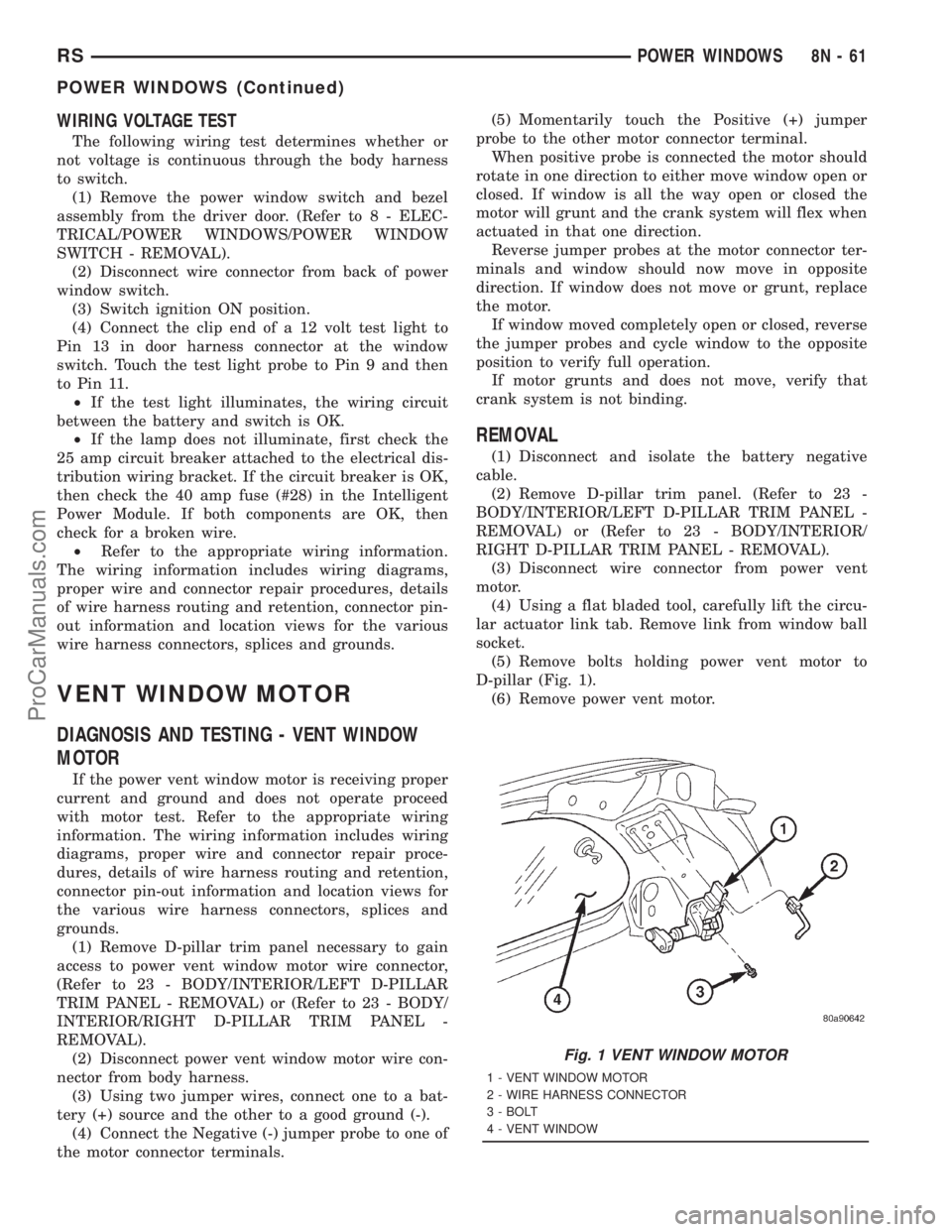
(5) Remove bolts holding power vent motor to
D-pillar (Fig. 1).
(6) Remove power vent motor.
Fig. 1 VENT WINDOW MOTOR
1 - VENT WINDOW MOTOR
2 - WIRE HARNESS CONNECTOR
3 - BOLT
4 - VENT WINDOW
RSPOWER WINDOWS8N-61
POWER WINDOWS (Continued)
ProCarManuals.com
Page 636 of 2321
8W-10 POWER DISTRIBUTION
Component PageA/C Compressor Clutch..................8Wa-10-19, 20, 38, 40
A/C Compressor Clutch Relay.............8Wa-10-19, 20, 37, 38, 40
Accessory Relay.......................8Wa-10-15, 26, 57
Ambient Temp Sensor........................8Wa-10-54
Auto Shut Down Relay......................8Wa-10-19, 34
Auto Temp Control.........................8Wa-10-33
Back-Up Lamp Switch........................8Wa-10-58
Battery........................8Wa-10-12, 13, 14, 34, 40
Blower Motor Resistor......................8Wa-10-17, 31
Body Control Module......8Wa-10-21, 33, 38, 41, 42, 44, 46, 47, 48, 49, 61
Brake Fluid Level Switch......................8Wa-10-57
Brake Lamp Switch.....................8Wa-10-21, 44, 59
Brake Transmission Shift Interlock Solenoid.............8Wa-10-55
Cabin Heater Assist.....................8Wa-10-20, 36, 52
Camshaft Position Sensor......................8Wa-10-37
Center High Mounted Stop Lamp..................8Wa-10-59
Clockspring.............................8Wa-10-53
Clutch Pedal Interlock Switch Jumper........8Wa-10-16, 30, 46, 47, 53
Clutch Pedal Interlock Switch............8Wa-10-16, 30, 46, 47, 53
Controller Antilock Brake...........8Wa-10-16, 21, 30, 42, 48, 54, 59
Crank Case Ventilation Heater...................8Wa-10-41
Data Link Connector.......................8Wa-10-29, 61
Defogger Relay......................8Wa-10-17, 18, 32, 56
Diagnostic Junction Port.......................8Wa-10-54
Driver Door Lock Switch.....................8Wa-10-28, 29
Driver Heated Seat Module.....................8Wa-10-42
Driver Power Seat Switch......................8Wa-10-42
Driver Power Window Switch....................8Wa-10-29
ECM/PCM Relay.........................8Wa-10-20, 36
EGR Solenoid..........................8Wa-10-37, 39
Electric Wiper De-Icer........................8Wa-10-28
Engine Control Module........8Wa-10-16, 20, 30, 36, 37, 40, 41, 58, 59
Floor Console Lamp.........................8Wa-10-27
Floor Console Power Outlet...................8Wa-10-27, 29
Front Blower Module......................8Wa-10-17, 31
Front Blower Motor Relay................8Wa-10-16, 17, 31, 56
Front Cigar Lighter.......................8Wa-10-15, 27
Front Control Module . . . 8Wa-10-14, 15, 16, 17, 18, 19, 20, 21, 22, 23, 24, 25,
26, 29, 30, 31, 32, 38, 40, 45, 46, 47, 50, 51, 52, 53, 54. 55, 56, 57, 58, 59, 61
Front Fog Lamp Relay....................8Wa-10-14, 22, 56
Front Washer Pump Motor..................8Wa-10-15, 26, 61
Front Wiper Hi/Low Relay..................8Wa-10-15, 25, 57
Front Wiper On/Off Relay..................8Wa-10-15, 25, 52
Fuel Heater.............................8Wa-10-41
Fuel Heater Relay......................8Wa-10-20, 40, 57
Fuel Injector No. 1..........................8Wa-10-35
Fuel Injector No. 2..........................8Wa-10-35
Fuel Injector No. 3..........................8Wa-10-35
Fuel Injector No. 4..........................8Wa-10-35
Fuel Injector No. 5..........................8Wa-10-35
Fuel Injector No. 6..........................8Wa-10-35
Fuel Pressure Solenoid.......................8Wa-10-37
Fuel Pump Module........................8Wa-10-19, 38
Fuel Pump Relay.......................8Wa-10-19, 38, 57
Fuse 1 (IPM).........................8Wa-10-14, 15, 22
Fuse 2 (IPM) (Diesel).....................8Wa-10-14, 10-24
Fuse 2 (IPM) (Gas)......................8Wa-10-14, 10-23
Fuse 3 (IPM).........................8Wa-10-14, 23, 24
Fuse 4 (IPM).......................8Wa-10-14, 15, 16, 25
Fuse 5 (IPM)...........................8Wa-10-15, 26
Fuse 6 (IPM)...........................8Wa-10-15, 26
Fuse 8 (IPM)...........................8Wa-10-16, 29
Fuse 9 (IPM).........................8Wa-10-16, 17, 30
Fuse 10 (IPM)..........................8Wa-10-17, 31
Fuse 11 (IPM)..........................8Wa-10-15, 26
Fuse 12 (IPM)..........................8Wa-10-17, 31
Fuse 13 (IPM)..........................8Wa-10-18, 32
Fuse 14 (IPM)....................8Wa-10-18, 19, 20, 32, 52
Fuse 15 (IPM) (Diesel)......................8Wa-10-20, 36
Fuse 15 (IPM) (Gas).....................8Wa-10-18, 19, 34
Fuse 16 (IPM) (Diesel)......................8Wa-10-20, 36
Fuse 16 (IPM) (Gas).......................8Wa-10-19, 34
Fuse 17 (IPM) (Diesel)......................8Wa-10-20, 40
Fuse 17 (IPM) (Gas).......................8Wa-10-19, 38
Fuse 18 (IPM)....................8Wa-10-19, 20, 21, 38, 40
Fuse 19 (IPM)......................8Wa-10-19, 20, 21, 42
Fuse 20 (IPM)..........................8Wa-10-21, 42
Fuse 21 (IPM)..........................8Wa-10-21, 42
Fuse 22 (IPM)..........................8Wa-10-21, 42
Fuse 23 (IPM)........................8Wa-10-21, 46, 47
Fuse 24 (IPM)............................8Wa-10-21
Fuse 24 (IPM)............................8Wa-10-44
Fuse 26 (IPM)..........................8Wa-10-21, 44
Fuse 27 (IPM)..........................8Wa-10-21, 44
Fuse 28 (IPM)..........................8Wa-10-15, 26
Fuse 30 (IPM)..........................8Wa-10-21, 45
Fuse 31 (IPM)..........................8Wa-10-21, 45
Fuse 32 (IPM)..........................8Wa-10-21, 45
Fuse 33 (IPM)............................8Wa-10-15
Fuse 33 (IPM)............................8Wa-10-26
Fuselink.............................8Wa-10-12, 13
G100................................8Wa-10-48
G101...............................8Wa-10-34, 40
G103................................8Wa-10-61
G300................................8Wa-10-50
G300................................8Wa-10-51
Generator........................8Wa-10-12, 13, 35, 37
Glow Plug Relay.........................8Wa-10-12, 37
Headlamp Switch........................8Wa-10-24, 55Component PageHeadlamp Washer Pump Motor.................8Wa-10-21, 45
Headlamp Washer Relay...................8Wa-10-21, 45, 56
High Note Horn...........................8Wa-10-29
Horn Relay..........................8Wa-10-16, 29, 52
Ignition Coil.............................8Wa-10-35
Ignition Switch............8Wa-10-16, 21, 30, 38, 39, 41, 46, 47, 53
Instrument Cluster.......................8Wa-10-21, 44
Intelligent Power Module . . 8Wa-10-2, 10-3, 10-4, 10-12, 14, 15, 16, 17, 18, 19,
20, 21, 22, 23, 24, 25, 26, 27, 28, 29, 30, 31, 32, 33, 34, 35, 36, 37, 38, 39, 40,
41, 42, 44, 45, 46, 47, 48, 49, 50, 51, 52, 53, 54, 55, 56, 57, 58, 59, 61
Leak Detection Pump........................8Wa-10-39
Left B-Pillar Switch.........................8Wa-10-28
Left Combination Relay.......................8Wa-10-60
Left Fog Lamp..........................8Wa-10-14, 22
Left Front Park/ Turn Signal Lamp............8Wa-10-14, 23, 49, 58
Left Headlamp............................8Wa-10-50
Left Headlamp Leveling Motor................8Wa-10-24, 55, 58
Left High Beam Lamp........................8Wa-10-51
Left Low Beam Lamp........................8Wa-10-51
Left Park Lamp.........................8Wa-10-24, 58
Left Power Mirror..........................8Wa-10-32
Left Rear Lamp Assembly..............8Wa-10-23, 24, 58, 59, 60
Left Repeater Lamp.........................8Wa-10-44
Left Side Impact Airbag Control Module...............8Wa-10-55
Left Sliding Door Control Module..................8Wa-10-45
Left Stop/ Turn Signal Relay.....................8Wa-10-60
Left Turn Signal Lamp.......................8Wa-10-49
License Lamp........................8Wa-10-23, 24, 58
Lift Pump Motor.........................8Wa-10-20, 36
Lift Pump Relay.........................8Wa-10-20, 36
Low Note Horn...........................8Wa-10-29
Mass Air Flow Sensor........................8Wa-10-37
Memory Seat/ Mirror Module....................8Wa-10-42
Message Center...........................8Wa-10-44
Name Brand Speaker Relay.................8Wa-10-18, 32, 52
Occupant Restraint Controller..................8Wa-10-56, 61
Overhead Console..........................8Wa-10-33
Oxygen Sensor 1/1 Upstream....................8Wa-10-35
Oxygen Sensor 1/2 Downstream...................8Wa-10-35
Park Lamp Relay.....................8Wa-10-14, 23, 24, 52
Park/ Neutral Position Switch....................8Wa-10-58
Passenger Door Lock Switch...................8Wa-10-26, 28
Passenger Folding Mirror Relay.............8Wa-10-19, 20, 38, 40
Passenger Heated Seat Module...................8Wa-10-43
Passenger Power Seat Switch....................8Wa-10-43
Passenger Power Window Switch..................8Wa-10-26
Power Liftgate Module......................8Wa-10-21, 45
Power Mirror Switch...................8Wa-10-19, 20, 39, 40
Power Outlet............................8Wa-10-29
Power Seat Circuit Breaker...................8Wa-10-21, 42
Power Window Circuit Breaker.................8Wa-10-15, 26
Powertrain Control Module........8Wa-10-16, 19, 30, 34, 35, 38, 39, 48
PTC4 ..............................8Wa-10-18, 32
Ptc7.............................8Wa-10-15, 16, 29
Radiator Fan Relay.....................8Wa-10-21, 44, 48
Radiator Fan Relay No. 1....................8Wa-10-12, 37
Radiator Fan Relay No. 2....................8Wa-10-37, 44
Radiator Fan Relay No. 3....................8Wa-10-21, 37
Radio..............................8Wa-10-27, 33
Radio Choke...........................8Wa-10-18, 32
Rear A/C-Heater Unit......................8Wa-10-17, 31
Rear Blower Motor Power Module..................8Wa-10-31
Rear Blower Motor Relay.................8Wa-10-17, 18, 31, 56
Rear Power Outlet......................8Wa-10-15, 26, 27
Rear Washer Pump Motor..................8Wa-10-15, 26, 61
Rear Window Defogger Grid...................8Wa-10-18, 32
Rear Wiper Motor..........................8Wa-10-28
Remote Keyless Entry Module....................8Wa-10-33
Right B-Pillar Switch........................8Wa-10-28
Right Combination Relay......................8Wa-10-60
Right Fog Lamp.........................8Wa-10-14, 22
Right Front Park/ Turn Signal Lamp...........8Wa-10-14, 23, 49, 53
Right Headlamp...........................8Wa-10-50
Right Headlamp Leveling Motor...............8Wa-10-24, 53, 55
Right High Beam Lamp.......................8Wa-10-51
Right Low Beam Lamp.......................8Wa-10-51
Right Park Lamp........................8Wa-10-24, 53
Right Power Mirror.........................8Wa-10-32
Right Rear Lamp Assembly................8Wa-10-14, 23, 24, 59
Right Repeater Lamp........................8Wa-10-44
Right Side Impact Airbag Control Module..............8Wa-10-55
Right Sliding Door Control Module.................8Wa-10-45
Right Stop/ Turn Signal Relay....................8Wa-10-60
Right Turn Signal Lamp.......................8Wa-10-49
Sentry Key Immobilizer Module...........8Wa-10-33, 39, 41, 46, 47
Solenoid/ Pressure Switch Assy...................8Wa-10-34
Starter Motor.......................8Wa-10-12, 13, 16, 30
Starter Motor Relay...................8Wa-10-16, 30, 46, 47
Thatcham Alarm Module.................8Wa-10-39, 41, 47, 61
Torque Converter Clutch Solenoid..................8Wa-10-39
Trailer Tow Connector......................8Wa-10-23, 58
Transmission Control Module...........8Wa-10-16, 19, 30, 34, 54, 55
Transmission Control Relay...................8Wa-10-19, 34
Transmission Range Sensor.....................8Wa-10-58
TXV Solenoid............................8Wa-10-31
Vehicle Speed Sensor........................8Wa-10-36
Washer Fluid Level Switch.....................8Wa-10-53
Wiper Module........................8Wa-10-15, 25, 52
RG8W-10 POWER DISTRIBUTION8Wa-10-1
ProCarManuals.com