2001 DODGE TOWN AND COUNTRY back
[x] Cancel search: backPage 86 of 2321
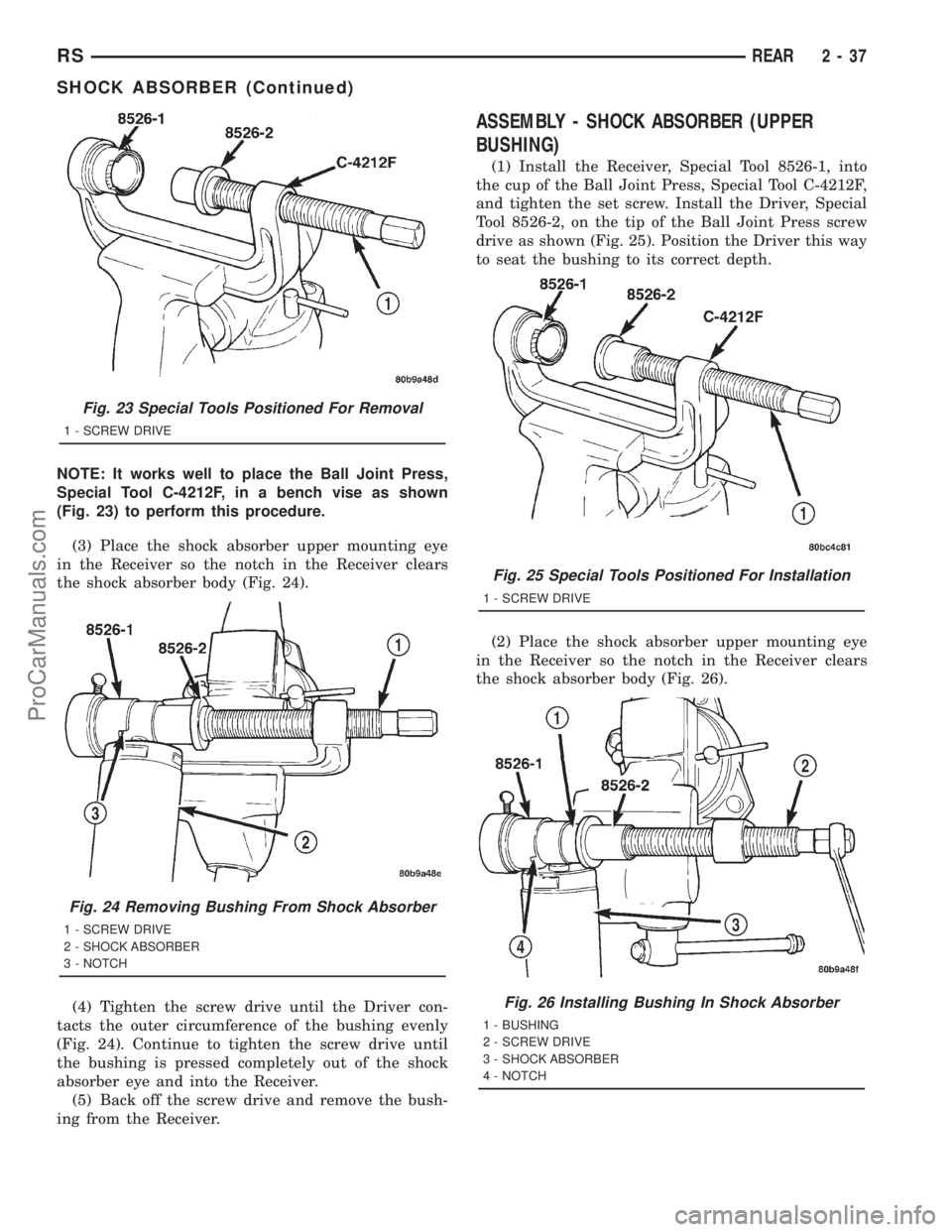
NOTE: It works well to place the Ball Joint Press,
Special Tool C-4212F, in a bench vise as shown
(Fig. 23) to perform this procedure.
(3) Place the shock absorber upper mounting eye
in the Receiver so the notch in the Receiver clears
the shock absorber body (Fig. 24).
(4) Tighten the screw drive until the Driver con-
tacts the outer circumference of the bushing evenly
(Fig. 24). Continue to tighten the screw drive until
the bushing is pressed completely out of the shock
absorber eye and into the Receiver.
(5) Back off the screw drive and remove the bush-
ing from the Receiver.
ASSEMBLY - SHOCK ABSORBER (UPPER
BUSHING)
(1) Install the Receiver, Special Tool 8526-1, into
the cup of the Ball Joint Press, Special Tool C-4212F,
and tighten the set screw. Install the Driver, Special
Tool 8526-2, on the tip of the Ball Joint Press screw
drive as shown (Fig. 25). Position the Driver this way
to seat the bushing to its correct depth.
(2) Place the shock absorber upper mounting eye
in the Receiver so the notch in the Receiver clears
the shock absorber body (Fig. 26).
Fig. 23 Special Tools Positioned For Removal
1 - SCREW DRIVE
Fig. 24 Removing Bushing From Shock Absorber
1 - SCREW DRIVE
2 - SHOCK ABSORBER
3 - NOTCH
Fig. 25 Special Tools Positioned For Installation
1 - SCREW DRIVE
Fig. 26 Installing Bushing In Shock Absorber
1 - BUSHING
2 - SCREW DRIVE
3 - SHOCK ABSORBER
4 - NOTCH
RSREAR2-37
SHOCK ABSORBER (Continued)
ProCarManuals.com
Page 87 of 2321
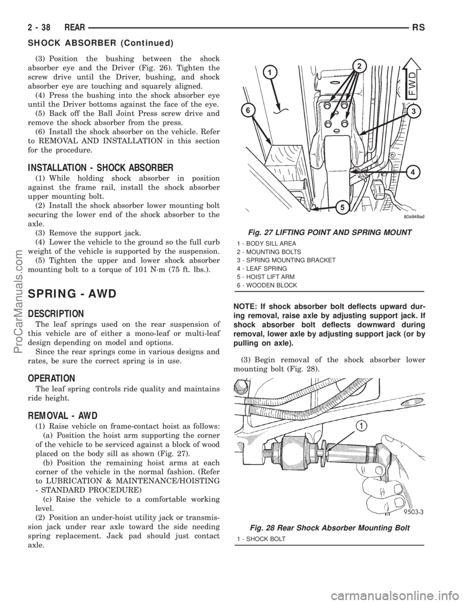
(3) Position the bushing between the shock
absorber eye and the Driver (Fig. 26). Tighten the
screw drive until the Driver, bushing, and shock
absorber eye are touching and squarely aligned.
(4) Press the bushing into the shock absorber eye
until the Driver bottoms against the face of the eye.
(5) Back off the Ball Joint Press screw drive and
remove the shock absorber from the press.
(6) Install the shock absorber on the vehicle. Refer
to REMOVAL AND INSTALLATION in this section
for the procedure.
INSTALLATION - SHOCK ABSORBER
(1) While holding shock absorber in position
against the frame rail, install the shock absorber
upper mounting bolt.
(2) Install the shock absorber lower mounting bolt
securing the lower end of the shock absorber to the
axle.
(3) Remove the support jack.
(4) Lower the vehicle to the ground so the full curb
weight of the vehicle is supported by the suspension.
(5) Tighten the upper and lower shock absorber
mounting bolt to a torque of 101 N´m (75 ft. lbs.).
SPRING - AWD
DESCRIPTION
The leaf springs used on the rear suspension of
this vehicle are of either a mono-leaf or multi-leaf
design depending on model and options.
Since the rear springs come in various designs and
rates, be sure the correct spring is in use.
OPERATION
The leaf spring controls ride quality and maintains
ride height.
REMOVAL - AWD
(1) Raise vehicle on frame-contact hoist as follows:
(a) Position the hoist arm supporting the corner
of the vehicle to be serviced against a block of wood
placed on the body sill as shown (Fig. 27).
(b) Position the remaining hoist arms at each
corner of the vehicle in the normal fashion. (Refer
to LUBRICATION & MAINTENANCE/HOISTING
- STANDARD PROCEDURE)
(c) Raise the vehicle to a comfortable working
level.
(2) Position an under-hoist utility jack or transmis-
sion jack under rear axle toward the side needing
spring replacement. Jack pad should just contact
axle.NOTE: If shock absorber bolt deflects upward dur-
ing removal, raise axle by adjusting support jack. If
shock absorber bolt deflects downward during
removal, lower axle by adjusting support jack (or by
pulling on axle).
(3) Begin removal of the shock absorber lower
mounting bolt (Fig. 28).
Fig. 27 LIFTING POINT AND SPRING MOUNT
1 - BODY SILL AREA
2 - MOUNTING BOLTS
3 - SPRING MOUNTING BRACKET
4 - LEAF SPRING
5 - HOIST LIFT ARM
6 - WOODEN BLOCK
Fig. 28 Rear Shock Absorber Mounting Bolt
1 - SHOCK BOLT
2 - 38 REARRS
SHOCK ABSORBER (Continued)
ProCarManuals.com
Page 102 of 2321
CAUTION: After slotting the strut clevis bracket
hole, do not install the original attaching bolts when
assembling the steering knuckle to the strut assem-
bly. Only the flange bolts, cam bolts, and dog bone
washers from the service package must be used to
attach the steering knuckle to the strut after the
mounting hole is slotted.
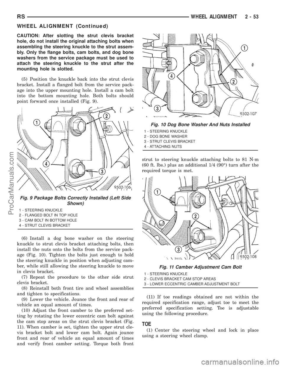
(5) Position the knuckle back into the strut clevis
bracket. Install a flanged bolt from the service pack-
age into the upper mounting hole. Install a cam bolt
into the bottom mounting hole. Both bolts should
point forward once installed (Fig. 9).
(6) Install a dog bone washer on the steering
knuckle to strut clevis bracket attaching bolts, then
install the nuts onto the bolts from the service pack-
age (Fig. 10). Tighten the bolts just enough to hold
the steering knuckle in position when adjusting cam-
ber, while still allowing the steering knuckle to move
in clevis bracket.
(7) Repeat the procedure to the other side strut
clevis bracket.
(8) Reinstall both front tire and wheel assemblies
and tighten to specifications.
(9) Lower the vehicle. Jounce the front and rear of
vehicle an equal amount of times.
(10) Adjust the front camber to the preferred set-
ting by rotating the lower eccentric cam bolt against
the cam stop areas on the strut clevis bracket (Fig.
11). When camber is set, tighten the upper strut cle-
vis bracket bolt and lower cam bolt. Again jounce
front and rear of vehicle an equal amount of times
and verify front camber setting. Torque both frontstrut to steering knuckle attaching bolts to 81 N´m
(60 ft. lbs.) plus an additional 1/4 (90É) turn after the
required torque is met.
(11) If toe readings obtained are not within the
required specification range, adjust toe to meet the
preferred specification setting. Toe is adjustable
using the following procedure.
TOE
(1) Center the steering wheel and lock in place
using a steering wheel clamp.
Fig. 9 Package Bolts Correctly Installed (Left Side
Shown)
1 - STEERING KNUCKLE
2 - FLANGED BOLT IN TOP HOLE
3 - CAM BOLT IN BOTTOM HOLE
4 - STRUT CLEVIS BRACKET
Fig. 10 Dog Bone Washer And Nuts Installed
1 - STEERING KNUCKLE
2 - DOG BONE WASHER
3 - STRUT CLEVIS BRACKET
4 - ATTACHING NUTS
Fig. 11 Camber Adjustment Cam Bolt
1 - STEERING KNUCKLE
2 - CLEVIS BRACKET CAM STOP AREAS
3 - LOWER ECCENTRIC CAMBER ADJUSTMENT BOLT
RSWHEEL ALIGNMENT2-53
WHEEL ALIGNMENT (Continued)
ProCarManuals.com
Page 111 of 2321
²Noise may also be caused by another component
of the vehicle coming in contact with the half shafts.
CLUNKING NOISE DURING ACCELERATION
This noise may be a result of one of the following
conditions:
²A torn seal boot on the inner or outer joint of the
half shaft assembly.
²A loose or missing clamp on the inner or outer
joint of the half shaft assembly.
²A damaged or worn half shaft CV joint.
SHUDDER OR VIBRATION DURING ACCELERATION
This problem could be a result of:
²A worn or damaged half shaft inner tripod joint.
²A sticking tripod joint spider assembly (inner tri-
pod joint only).
²Improper wheel alignment. (Refer to 2 - SUS-
PENSION/WHEEL ALIGNMENT - STANDARD
PROCEDURE)
VIBRATION AT HIGHWAY SPEEDS
This problem could be a result of:
²Foreign material (mud, etc.) packed on the back-
side of the wheel(s).
²Out of balance tires or wheels. (Refer to 22 -
TIRES/WHEELS - STANDARD PROCEDURE)
²Improper tire and/or wheel runout. (Refer to 22 -
TIRES/WHEELS - DIAGNOSIS AND TESTING)
REMOVAL
(1) Raise vehicle on jack stands or centered on a
frame contact type hoist.
(2) Remove the cotter pin and nut lock (Fig. 2)
from the end of the half shaft.
(3) Remove the wave washer (Fig. 3) from the end
of the half shaft.
(4) Remove the wheel and tire assembly from the
vehicle. (Refer to 22 - TIRES/WHEELS - REMOVAL)
(5) With the vehicle's brakes applied to keep hub
from turning,loosen and removethe half shaft
nut.
(6) Remove the two front disc brake caliper
adapter to steering knuckle attaching bolts (Fig. 4).
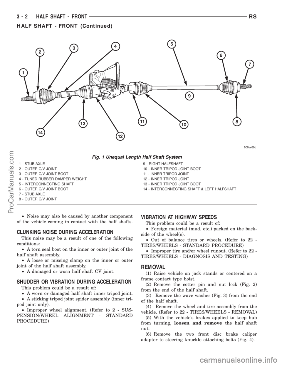
Fig. 1 Unequal Length Half Shaft System
1 - STUB AXLE
2 - OUTER C/V JOINT
3 - OUTER C/V JOINT BOOT
4 - TUNED RUBBER DAMPER WEIGHT
5 - INTERCONNECTING SHAFT
6 - OUTER C/V JOINT BOOT
7 - STUB AXLE
8 - OUTER C/V JOINT9 - RIGHT HALFSHAFT
10 - INNER TRIPOD JOINT BOOT
11 - INNER TRIPOD JOINT
12 - INNER TRIPOD JOINT
13 - INNER TRIPOD JOINT BOOT
14 - INTERCONNECTING SHAFT & LEFT HALFSHAFT
3 - 2 HALF SHAFT - FRONTRS
HALF SHAFT - FRONT (Continued)
ProCarManuals.com
Page 114 of 2321
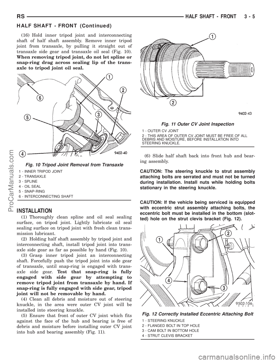
(16) Hold inner tripod joint and interconnecting
shaft of half shaft assembly. Remove inner tripod
joint from transaxle, by pulling it straight out of
transaxle side gear and transaxle oil seal (Fig. 10).
When removing tripod joint, do not let spline or
snap-ring drag across sealing lip of the trans-
axle to tripod joint oil seal.
INSTALLATION
(1) Thoroughly clean spline and oil seal sealing
surface, on tripod joint. Lightly lubricate oil seal
sealing surface on tripod joint with fresh clean trans-
mission lubricant.
(2) Holding half shaft assembly by tripod joint and
interconnecting shaft, install tripod joint into trans-
axle side gear as far as possible by hand (Fig. 10).
(3) Grasp inner tripod joint an interconnecting
shaft. Forcefully push the tripod joint into side gear
of transaxle, until snap-ring is engaged with trans-
axle side gear.Test that snap-ring is fully
engaged with side gear by attempting to
remove tripod joint from transaxle by hand. If
snap-ring is fully engaged with side gear, tripod
joint will not be removable by hand.
(4) Clean all debris and moisture out of steering
knuckle, in the area were outer CV joint will be
installed into steering knuckle.
(5) Ensure that front of outer CV joint which fits
against the face of the hub and bearing is free of
debris and moisture before installing outer CV joint
into hub and bearing assembly (Fig. 11).(6) Slide half shaft back into front hub and bear-
ing assembly.
CAUTION: The steering knuckle to strut assembly
attaching bolts are serrated and must not be turned
during installation. Install nuts while holding bolts
stationary in the steering knuckle.
CAUTION: If the vehicle being serviced is equipped
with eccentric strut assembly attaching bolts, the
eccentric bolt must be installed in the bottom (slot-
ted) hole on the strut clevis bracket (Fig. 12).
Fig. 10 Tripod Joint Removal from Transaxle
1 - INNER TRIPOD JOINT
2 - TRANSAXLE
3 - SPLINE
4 - OIL SEAL
5 - SNAP-RING
6 - INTERCONNECTING SHAFT
Fig. 11 Outer CV Joint Inspection
1 - OUTER CV JOINT
2 - THIS AREA OF OUTER CV JOINT MUST BE FREE OF ALL
DEBRIS AND MOISTURE, BEFORE INSTALLATION INTO
STEERING KNUCKLE.
Fig. 12 Correctly Installed Eccentric Attaching Bolt
1 - STEERING KNUCKLE
2 - FLANGED BOLT IN TOP HOLE
3 - CAM BOLT IN BOTTOM HOLE
4 - STRUT CLEVIS BRACKET
RSHALF SHAFT - FRONT3-5
HALF SHAFT - FRONT (Continued)
ProCarManuals.com
Page 120 of 2321
LATCHING TYPE BOOT CLAMP
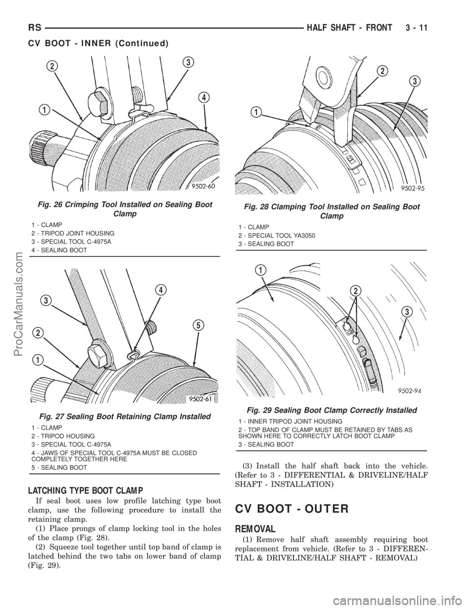
If seal boot uses low profile latching type boot
clamp, use the following procedure to install the
retaining clamp.
(1) Place prongs of clamp locking tool in the holes
of the clamp (Fig. 28).
(2) Squeeze tool together until top band of clamp is
latched behind the two tabs on lower band of clamp
(Fig. 29).(3) Install the half shaft back into the vehicle.
(Refer to 3 - DIFFERENTIAL & DRIVELINE/HALF
SHAFT - INSTALLATION)
CV BOOT - OUTER
REMOVAL
(1) Remove half shaft assembly requiring boot
replacement from vehicle. (Refer to 3 - DIFFEREN-
TIAL & DRIVELINE/HALF SHAFT - REMOVAL)
Fig. 26 Crimping Tool Installed on Sealing Boot
Clamp
1 - CLAMP
2 - TRIPOD JOINT HOUSING
3 - SPECIAL TOOL C-4975A
4 - SEALING BOOT
Fig. 27 Sealing Boot Retaining Clamp Installed
1 - CLAMP
2 - TRIPOD HOUSING
3 - SPECIAL TOOL C-4975A
4 - JAWS OF SPECIAL TOOL C-4975A MUST BE CLOSED
COMPLETELY TOGETHER HERE
5 - SEALING BOOT
Fig. 28 Clamping Tool Installed on Sealing Boot
Clamp
1 - CLAMP
2 - SPECIAL TOOL YA3050
3 - SEALING BOOT
Fig. 29 Sealing Boot Clamp Correctly Installed
1 - INNER TRIPOD JOINT HOUSING
2 - TOP BAND OF CLAMP MUST BE RETAINED BY TABS AS
SHOWN HERE TO CORRECTLY LATCH BOOT CLAMP
3 - SEALING BOOT
RSHALF SHAFT - FRONT3-11
CV BOOT - INNER (Continued)
ProCarManuals.com
Page 123 of 2321
(11) Install the half shaft requiring boot replace-
ment back on the vehicle. (Refer to 3 - DIFFEREN-
TIAL & DRIVELINE/HALF SHAFT -
INSTALLATION)
OUTER CV JOINT BEARING
SHIELD
REMOVAL
(1) Clamp half shaft in a vise by the interconnect-
ing shaft.
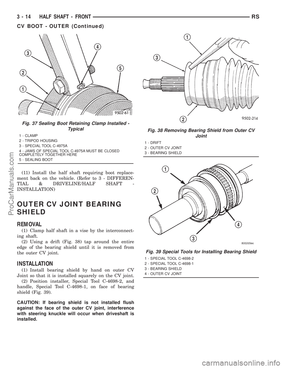
(2) Using a drift (Fig. 38) tap around the entire
edge of the bearing shield until it is removed from
the outer CV joint.
INSTALLATION
(1) Install bearing shield by hand on outer CV
Joint so that it is installed squarely on the CV joint.
(2) Position installer, Special Tool C-4698-2, and
handle, Special Tool C-4698-1, on face of bearing
shield (Fig. 39).
CAUTION: If bearing shield is not installed flush
against the face of the outer CV joint, interference
with steering knuckle will occur when driveshaft is
installed.
Fig. 37 Sealing Boot Retaining Clamp Installed -
Typical
1 - CLAMP
2 - TRIPOD HOUSING
3 - SPECIAL TOOL C-4975A
4 - JAWS OF SPECIAL TOOL C-4975A MUST BE CLOSED
COMPLETELY TOGETHER HERE
5 - SEALING BOOT
Fig. 38 Removing Bearing Shield from Outer CV
Joint
1 - DRIFT
2 - OUTER CV JOINT
3 - BEARING SHIELD
Fig. 39 Special Tools for Installing Bearing Shield
1 - SPECIAL TOOL C-4698-2
2 - SPECIAL TOOL C-4698-1
3 - BEARING SHIELD
4 - OUTER CV JOINT
3 - 14 HALF SHAFT - FRONTRS
CV BOOT - OUTER (Continued)
ProCarManuals.com
Page 125 of 2321
HALF SHAFT - REAR
TABLE OF CONTENTS
page page
HALF SHAFT - REAR
DESCRIPTION...........................16
DIAGNOSIS AND TESTING.................16
HALF SHAFT..........................16
REMOVAL..............................16INSTALLATION...........................17
SPECIFICATIONS........................18
CV BOOT - INNER/OUTER
REMOVAL..............................18
INSTALLATION...........................20
HALF SHAFT - REAR
DESCRIPTION
The inner and outer joints of both half shaft
assemblies are tripod joints. The tripod joints are
true constant velocity (CV) joint assemblies, which
allow for the changes in half shaft length through
the jounce and rebound travel of the rear suspension.
On vehicles equipped with ABS brakes, the outer
CV joint is equipped with a tone wheel used to deter-
mine vehicle speed for ABS brake operation.
The inner tripod joint of both half shafts is bolted
rear differential assembly's output flanges. The outer
CV joint has a stub shaft that is splined into the
wheel hub and retained by a steel hub nut.
DIAGNOSIS AND TESTING - HALF SHAFT
VEHICLE INSPECTION
(1) Check for grease in the vicinity of the inboard
tripod joint and outboard CV joint; this is a sign of
inner or outer joint seal boot or seal boot clamp dam-
age.
(2) A light film of grease may appear on the right
inner tripod joint seal boot; this is considered normal
and should not require replacement of the seal boot.
NOISE AND/OR VIBRATION IN TURNS
A clicking noise and/or a vibration in turns could
be caused by one of the following conditions:
²Damaged outer CV or inner tripod joint seal
boot or seal boot clamps. This will result in the loss
and/or contamination of the joint grease, resulting in
inadequate lubrication of the joint.
²Noise may also be caused by another component
of the vehicle coming in contact with the half shafts.
CLUNKING NOISE DURING ACCELERATION
This noise may be a result of one of the following
conditions:²A torn seal boot on the inner or outer joint of the
half shaft assembly.
²A loose or missing clamp on the inner or outer
joint of the half shaft assembly.
²A damaged or worn half shaft CV joint.
SHUDDER OR VIBRATION DURING ACCELERATION
This problem could be a result of:
²A worn or damaged half shaft inner tripod joint.
²A sticking tripod joint spider assembly (inner tri-
pod joint only).
²Improper wheel alignment. (Refer to 2 - SUS-
PENSION/WHEEL ALIGNMENT - STANDARD
PROCEDURE)
VIBRATION AT HIGHWAY SPEEDS
This problem could be a result of:
²Foreign material (mud, etc.) packed on the back-
side of the wheel(s).
²Out of balance tires or wheels. (Refer to 22 -
TIRES/WHEELS - STANDARD PROCEDURE)
²Improper tire and/or wheel runout. (Refer to 22 -
TIRES/WHEELS - DIAGNOSIS AND TESTING)
REMOVAL
(1) Lift vehicle on hoist so that the wheels hang
freely.
(2) Remove rear wheel.
(3) Remove cotter pin, nut lock, and wave washer
(Fig. 1).
(4) Remove hub nut and washer.
CAUTION: The half shaft outer CV joint, when
installed, acts as a bolt and secures the hub/bear-
ing assembly. If the vehicle is to be supported or
moved on its wheels, install and torque a bolt
through the hub. This will ensure that the hub/bear-
ing assembly cannot loosen.
(5) Remove inner half shaft retaining bolts (Fig. 2).
3 - 16 HALF SHAFT - REARRS
ProCarManuals.com