2001 DODGE TOWN AND COUNTRY back
[x] Cancel search: backPage 54 of 2321
DIAGNOSIS AND TESTING - HUB AND
BEARING (FRONT)
The condition of the front hub and bearing assem-
bly is diagnosed using the inspection and testing pro-
cedure detailed below.
The bearing contained in the Unit III front hub/
bearing assembly will produce noise and vibration
when worn or damaged. The noise will generally
change when the bearings are loaded. A road test of
the vehicle is normally required to determine the
location of a worn or damaged bearing.
Find a smooth level road surface and bring the
vehicle up to a constant speed. When vehicle is at a
constant speed, swerve the vehicle back and forth
from the left and to the right. This will load and
unload the bearings and change the noise level.
Where axle bearing damage is slight, the noise is
usually not noticeable at speeds above 48 km/h (30
mph).
REMOVAL - HUB AND BEARING
NOTE: Replacement of the Unit III front hub/bearing
assembly can be normally done without having to
remove the steering knuckle from the vehicle. In the
event that the hub/bearing is frozen in the steering
knuckle and cannot be removed by hand, it will
have to be pressed out of the steering knuckle. The
steering knuckle will require removal from the vehi-
cle to allow the hub/bearing assembly to be
pressed out of the steering knuckle. (Refer to 2 -
SUSPENSION/FRONT/KNUCKLE - REMOVAL)
(1) Raise vehicle on jack stands or centered on a
frame contact type hoist. See Hoisting in Lubrication
and Maintenance.
(2) Remove wheel lug nuts, and front tire and
wheel assembly.
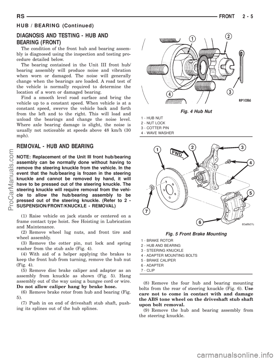
(3) Remove the cotter pin, nut lock and spring
washer from the stub axle (Fig. 4).
(4) With aid of a helper applying the brakes to
keep the front hub from turning, remove the hub nut
(Fig. 4).
(5) Remove disc brake caliper and adapter as an
assembly from knuckle as shown (Fig. 5). Hang
assembly out of the way using a bungee cord or wire.
Do not allow caliper hang by brake hose.
(6) Remove brake rotor from hub and bearing (Fig.
5).
(7) Push in on end of driveshaft stub shaft, push-
ing its splines out of the hub splines.(8) Remove the four hub and bearing mounting
bolts from the rear of steering knuckle (Fig. 6).Use
care not to come in contact with and damage
the ABS tone wheel on the driveshaft stub shaft
upon bolt removal.
(9) Remove the hub and bearing assembly from
the steering knuckle.
Fig. 4 Hub Nut
1 - HUB NUT
2 - NUT LOCK
3 - COTTER PIN
4 - WAVE WASHER
Fig. 5 Front Brake Mounting
1 - BRAKE ROTOR
2 - HUB AND BEARING
3 - STEERING KNUCKLE
4 - ADAPTER MOUNTING BOLTS
5 - BRAKE CALIPER
6 - ADAPTER
7 - CLIP
RSFRONT2-5
HUB / BEARING (Continued)
ProCarManuals.com
Page 55 of 2321
INSTALLATION - HUB AND BEARING
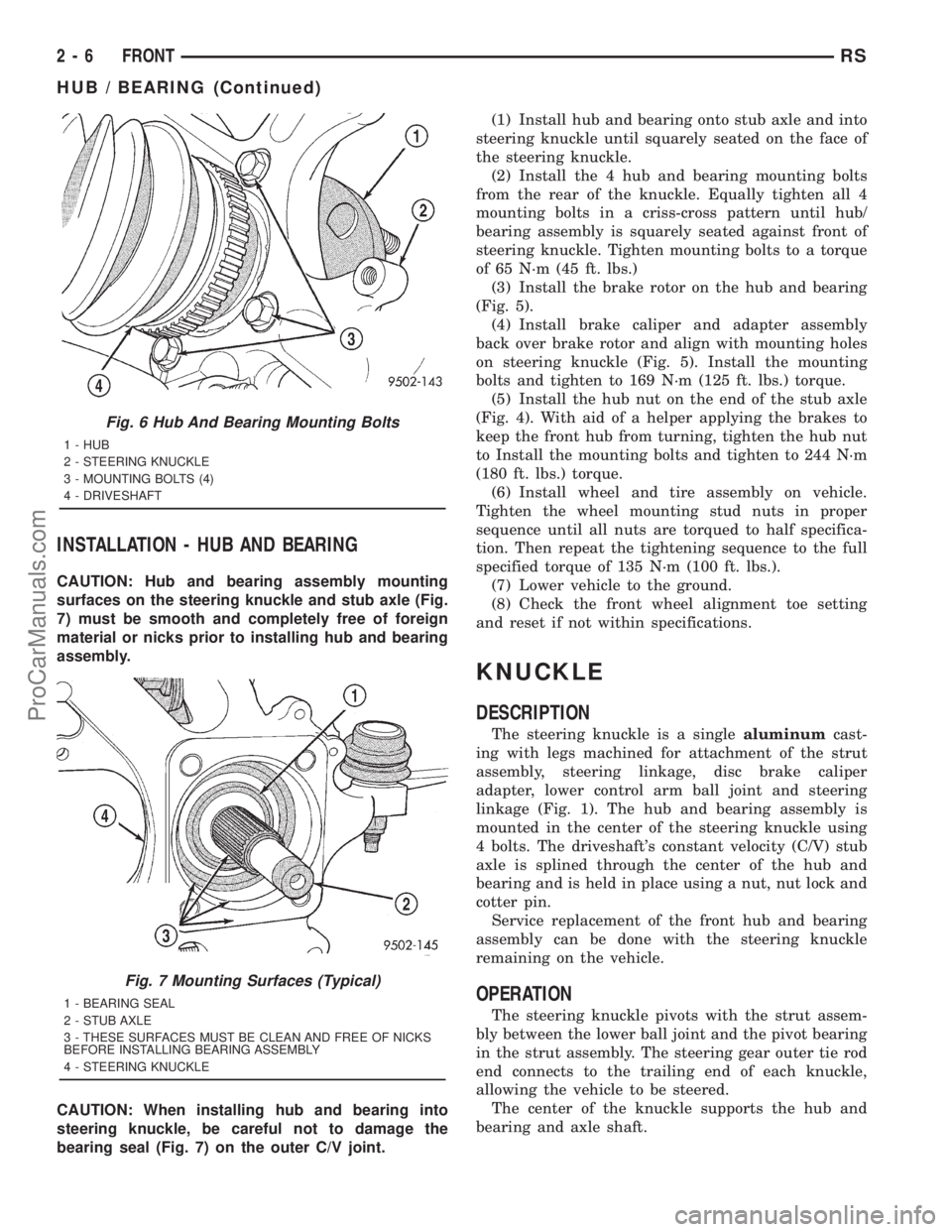
CAUTION: Hub and bearing assembly mounting
surfaces on the steering knuckle and stub axle (Fig.
7) must be smooth and completely free of foreign
material or nicks prior to installing hub and bearing
assembly.
CAUTION: When installing hub and bearing into
steering knuckle, be careful not to damage the
bearing seal (Fig. 7) on the outer C/V joint.(1) Install hub and bearing onto stub axle and into
steering knuckle until squarely seated on the face of
the steering knuckle.
(2) Install the 4 hub and bearing mounting bolts
from the rear of the knuckle. Equally tighten all 4
mounting bolts in a criss-cross pattern until hub/
bearing assembly is squarely seated against front of
steering knuckle. Tighten mounting bolts to a torque
of 65 N´m (45 ft. lbs.)
(3) Install the brake rotor on the hub and bearing
(Fig. 5).
(4) Install brake caliper and adapter assembly
back over brake rotor and align with mounting holes
on steering knuckle (Fig. 5). Install the mounting
bolts and tighten to 169 N´m (125 ft. lbs.) torque.
(5) Install the hub nut on the end of the stub axle
(Fig. 4). With aid of a helper applying the brakes to
keep the front hub from turning, tighten the hub nut
to Install the mounting bolts and tighten to 244 N´m
(180 ft. lbs.) torque.
(6) Install wheel and tire assembly on vehicle.
Tighten the wheel mounting stud nuts in proper
sequence until all nuts are torqued to half specifica-
tion. Then repeat the tightening sequence to the full
specified torque of 135 N´m (100 ft. lbs.).
(7) Lower vehicle to the ground.
(8) Check the front wheel alignment toe setting
and reset if not within specifications.
KNUCKLE
DESCRIPTION
The steering knuckle is a singlealuminumcast-
ing with legs machined for attachment of the strut
assembly, steering linkage, disc brake caliper
adapter, lower control arm ball joint and steering
linkage (Fig. 1). The hub and bearing assembly is
mounted in the center of the steering knuckle using
4 bolts. The driveshaft's constant velocity (C/V) stub
axle is splined through the center of the hub and
bearing and is held in place using a nut, nut lock and
cotter pin.
Service replacement of the front hub and bearing
assembly can be done with the steering knuckle
remaining on the vehicle.
OPERATION
The steering knuckle pivots with the strut assem-
bly between the lower ball joint and the pivot bearing
in the strut assembly. The steering gear outer tie rod
end connects to the trailing end of each knuckle,
allowing the vehicle to be steered.
The center of the knuckle supports the hub and
bearing and axle shaft.
Fig. 6 Hub And Bearing Mounting Bolts
1 - HUB
2 - STEERING KNUCKLE
3 - MOUNTING BOLTS (4)
4 - DRIVESHAFT
Fig. 7 Mounting Surfaces (Typical)
1 - BEARING SEAL
2 - STUB AXLE
3 - THESE SURFACES MUST BE CLEAN AND FREE OF NICKS
BEFORE INSTALLING BEARING ASSEMBLY
4 - STEERING KNUCKLE
2 - 6 FRONTRS
HUB / BEARING (Continued)
ProCarManuals.com
Page 64 of 2321
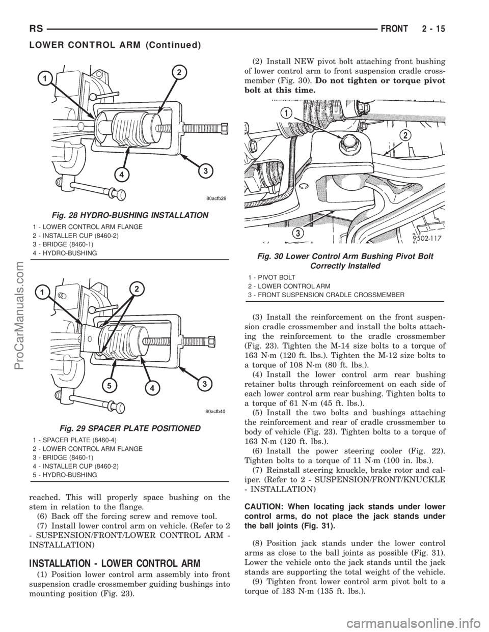
reached. This will properly space bushing on the
stem in relation to the flange.
(6) Back off the forcing screw and remove tool.
(7) Install lower control arm on vehicle. (Refer to 2
- SUSPENSION/FRONT/LOWER CONTROL ARM -
INSTALLATION)
INSTALLATION - LOWER CONTROL ARM
(1) Position lower control arm assembly into front
suspension cradle crossmember guiding bushings into
mounting position (Fig. 23).(2) Install NEW pivot bolt attaching front bushing
of lower control arm to front suspension cradle cross-
member (Fig. 30).Do not tighten or torque pivot
bolt at this time.
(3) Install the reinforcement on the front suspen-
sion cradle crossmember and install the bolts attach-
ing the reinforcement to the cradle crossmember
(Fig. 23). Tighten the M-14 size bolts to a torque of
163 N´m (120 ft. lbs.). Tighten the M-12 size bolts to
a torque of 108 N´m (80 ft. lbs.).
(4) Install the lower control arm rear bushing
retainer bolts through reinforcement on each side of
each lower control arm rear bushing. Tighten bolts to
a torque of 61 N´m (45 ft. lbs.).
(5) Install the two bolts and bushings attaching
the reinforcement and rear of cradle crossmember to
body of vehicle (Fig. 23). Tighten bolts to a torque of
163 N´m (120 ft. lbs.).
(6) Install the power steering cooler (Fig. 22).
Tighten bolts to a torque of 11 N´m (100 in. lbs.).
(7) Reinstall steering knuckle, brake rotor and cal-
iper. (Refer to 2 - SUSPENSION/FRONT/KNUCKLE
- INSTALLATION)
CAUTION: When locating jack stands under lower
control arms, do not place the jack stands under
the ball joints (Fig. 31).
(8) Position jack stands under the lower control
arms as close to the ball joints as possible (Fig. 31).
Lower the vehicle onto the jack stands until the jack
stands are supporting the total weight of the vehicle.
(9) Tighten front lower control arm pivot bolt to a
torque of 183 N´m (135 ft. lbs.).
Fig. 28 HYDRO-BUSHING INSTALLATION
1 - LOWER CONTROL ARM FLANGE
2 - INSTALLER CUP (8460-2)
3 - BRIDGE (8460-1)
4 - HYDRO-BUSHING
Fig. 29 SPACER PLATE POSITIONED
1 - SPACER PLATE (8460-4)
2 - LOWER CONTROL ARM FLANGE
3 - BRIDGE (8460-1)
4 - INSTALLER CUP (8460-2)
5 - HYDRO-BUSHING
Fig. 30 Lower Control Arm Bushing Pivot Bolt
Correctly Installed
1 - PIVOT BOLT
2 - LOWER CONTROL ARM
3 - FRONT SUSPENSION CRADLE CROSSMEMBER
RSFRONT2-15
LOWER CONTROL ARM (Continued)
ProCarManuals.com
Page 71 of 2321
(1) Position the strut assembly in the strut coil
spring compressor following the manufacturers
instructions. Position the lower hooks on the coil
spring first. The strut clevis bracket should be posi-
tioned straight outward from the compressor.
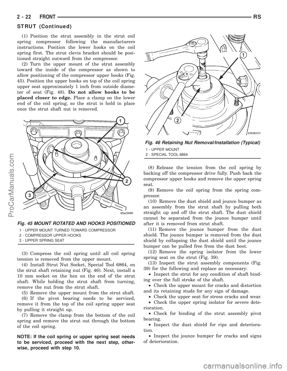
(2) Turn the upper mount of the strut assembly
toward the inside of the compressor as shown to
allow positioning of the compressor upper hooks (Fig.
45). Position the upper hooks on top of the coil spring
upper seat approximately 1 inch from outside diame-
ter of seat (Fig. 48).Do not allow hooks to be
placed closer to edge.Place a clamp on the lower
end of the coil spring, so the strut is held in place
once the strut shaft nut is removed.
(3) Compress the coil spring until all coil spring
tension is removed from the upper mount.
(4) Install Strut Nut Socket, Special Tool 6864, on
the strut shaft retaining nut (Fig. 46). Next, install a
10 mm socket on the hex on the end of the strut
shaft. While holding the strut shaft from turning,
remove the nut from the strut shaft.
(5) Remove the upper mount from the strut shaft.
(6) If the pivot bearing needs to be serviced,
remove it from the top of the coil spring upper seat
by pulling it straight up.
(7) Remove the clamp from the bottom of the coil
spring and remove the strut out through the bottom
of the coil spring.
NOTE: If the coil spring or upper spring seat needs
to be serviced, proceed with the next step, other-
wise, proceed with step 10.(8) Release the tension from the coil spring by
backing off the compressor drive fully. Push back the
compressor upper hooks and remove the upper spring
seat.
(9) Remove the coil spring from the spring com-
pressor.
(10) Remove the dust shield and jounce bumper as
an assembly from the strut shaft by pulling both
straight up and off the strut shaft. The dust shield
cannot be separated from the jounce bumper until
after it is removed from strut shaft.
(11) Remove the jounce bumper from the dust
shield. The jounce bumper is removed from the dust
shield by collapsing the dust shield until the jounce
bumper can be pulled free from the dust boot.
(12) Remove the spring isolator from the lower
spring seat on the strut (Fig. 39).
(13) Inspect the strut assembly components (Fig.
39) for the following and replace as necessary:
²Inspect the strut for any condition of shaft bind-
ing over the full stroke of the shaft.
²Check the upper mount for cracks and distortion
and its retaining studs for any sign of damage.
²Check the upper seat for stress cracks and wear.
²Check the upper spring isolator for severe dete-
rioration.
²Check for binding of the strut assembly pivot
bearing.
²Inspect the dust shield for rips and deteriora-
tion.
²Inspect the jounce bumper for cracks and signs
of deterioration.
Fig. 45 MOUNT ROTATED AND HOOKS POSITIONED
1 - UPPER MOUNT TURNED TOWARD COMPRESSOR
2 - COMPRESSOR UPPER HOOKS
3 - UPPER SPRING SEAT
Fig. 46 Retaining Nut Removal/Installation (Typical)
1 - UPPER MOUNT
2 - SPECIAL TOOL 6864
2 - 22 FRONTRS
STRUT (Continued)
ProCarManuals.com
Page 72 of 2321
ASSEMBLY - STRUT ASSEMBLY
For the disassembly and assembly of the strut
assembly, use of Strut Spring Compressor, Pentastar
Service Equipment (PSE) tool W-7200, or the equiva-
lent, is recommended to compress the coil spring.
Follow the manufacturer's instructions closely.
NOTE: Coil Springs on this vehicle are side-ori-
ented. Springs on the left side of the vehicle have a
left-hand wind top-to-bottom while springs on the
right side have a right-hand wind top-to-bottom.
Left and right springs must not be interchanged.
NOTE: If the coil spring has been removed from the
spring compressor, proceed with the next step, oth-
erwise, proceed with step 5.
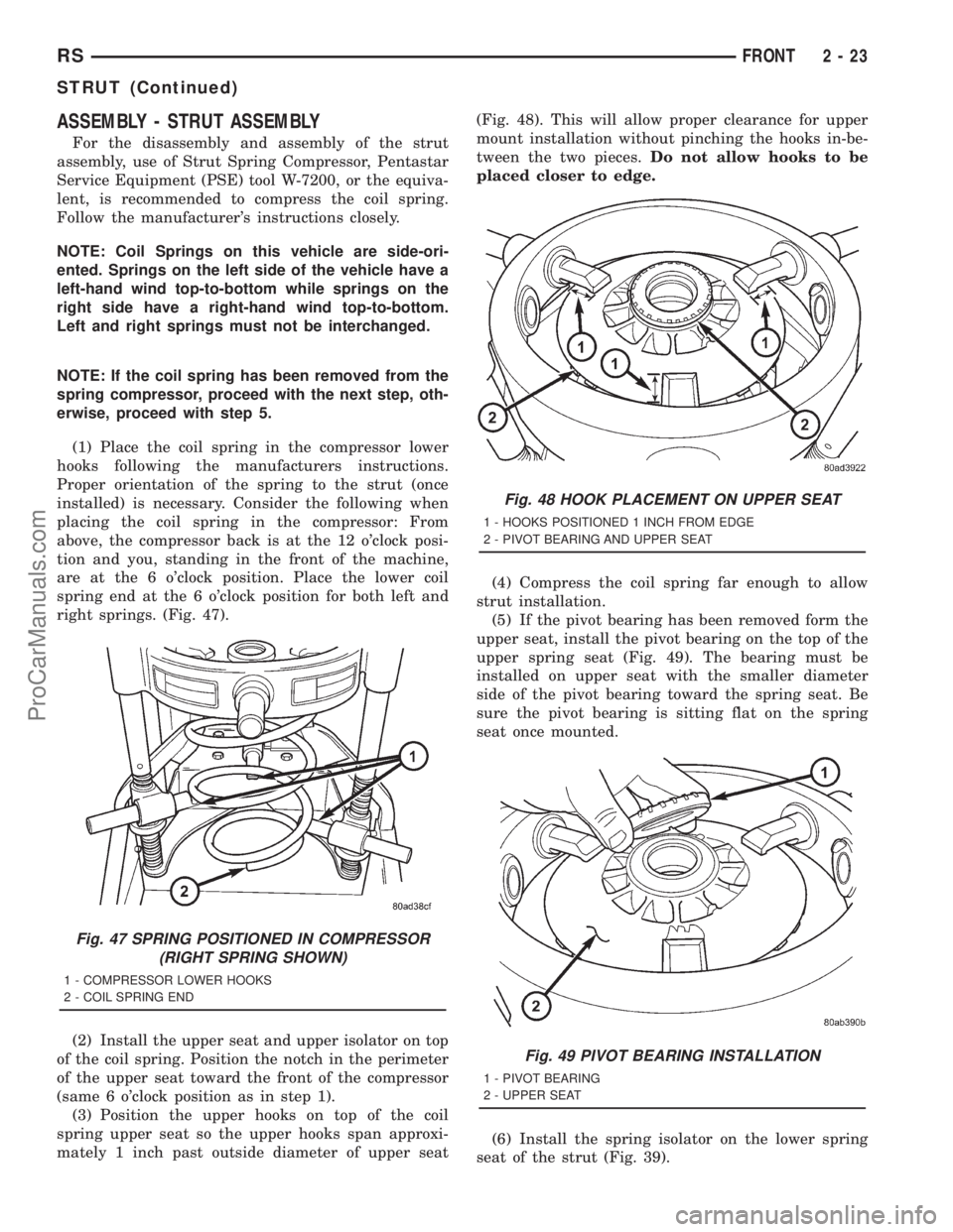
(1) Place the coil spring in the compressor lower
hooks following the manufacturers instructions.
Proper orientation of the spring to the strut (once
installed) is necessary. Consider the following when
placing the coil spring in the compressor: From
above, the compressor back is at the 12 o'clock posi-
tion and you, standing in the front of the machine,
are at the 6 o'clock position. Place the lower coil
spring end at the 6 o'clock position for both left and
right springs. (Fig. 47).
(2) Install the upper seat and upper isolator on top
of the coil spring. Position the notch in the perimeter
of the upper seat toward the front of the compressor
(same 6 o'clock position as in step 1).
(3) Position the upper hooks on top of the coil
spring upper seat so the upper hooks span approxi-
mately 1 inch past outside diameter of upper seat(Fig. 48). This will allow proper clearance for upper
mount installation without pinching the hooks in-be-
tween the two pieces.Do not allow hooks to be
placed closer to edge.
(4) Compress the coil spring far enough to allow
strut installation.
(5) If the pivot bearing has been removed form the
upper seat, install the pivot bearing on the top of the
upper spring seat (Fig. 49). The bearing must be
installed on upper seat with the smaller diameter
side of the pivot bearing toward the spring seat. Be
sure the pivot bearing is sitting flat on the spring
seat once mounted.
(6) Install the spring isolator on the lower spring
seat of the strut (Fig. 39).
Fig. 47 SPRING POSITIONED IN COMPRESSOR
(RIGHT SPRING SHOWN)
1 - COMPRESSOR LOWER HOOKS
2 - COIL SPRING END
Fig. 48 HOOK PLACEMENT ON UPPER SEAT
1 - HOOKS POSITIONED 1 INCH FROM EDGE
2 - PIVOT BEARING AND UPPER SEAT
Fig. 49 PIVOT BEARING INSTALLATION
1 - PIVOT BEARING
2 - UPPER SEAT
RSFRONT2-23
STRUT (Continued)
ProCarManuals.com
Page 73 of 2321
(7) Install the jounce bumper on the strut shaft
(Fig. 39). The jounce bumper is to be installed with
the small end pointing downward.
(8) Install the dust shield on the strut. Collapse
and stretch the dust shield down over the top of the
jounce bumper until the dust shield snaps into the
slot on the jounce bumper. The jounce bumper will be
at the top of the inner dust boot. Return the dust
shield to its fully extended length.
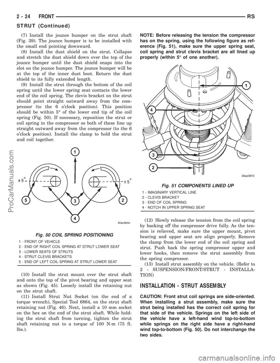
(9) Install the strut through the bottom of the coil
spring until the lower spring seat contacts the lower
end of the coil spring. The clevis bracket on the strut
should point straight outward away from the com-
pressor (to the 6 o'clock position). This position
should be within 5É of the lower end tip of the coil
spring (Fig. 50). If necessary, reposition the strut or
coil spring in the compressor so both of these line up
straight outward away from the compressor (to the 6
o'clock position). Install the clamp to hold the strut
and coil together.
(10) Install the strut mount over the strut shaft
and onto the top of the pivot bearing and upper seat
as shown (Fig. 45). Loosely install the retaining nut
on the strut shaft.
(11) Install Strut Nut Socket (on the end of a
torque wrench), Special Tool 6864, on the strut shaft
retaining nut (Fig. 46). Next, install a 10 mm socket
on the hex on the end of the strut shaft. While hold-
ing the strut shaft from turning, tighten the strut
shaft retaining nut to a torque of 100 N´m (75 ft.
lbs.).NOTE: Before releasing the tension the compressor
has on the spring, using the following figure as ref-
erence (Fig. 51), make sure the upper spring seat,
coil spring and strut clevis bracket are all lined up
properly (within 5É of one another).
(12) Slowly release the tension from the coil spring
by backing off the compressor drive fully. As the ten-
sion is relieved, make sure the upper mount, pivot
bearing and upper seat are align properly. Remove
the clamp from the lower end of the coil spring and
strut. Push back the spring compressor upper and
lower hooks, then remove the strut assembly from
the spring compressor.
(13) Install strut assembly on the vehicle. (Refer to
2 - SUSPENSION/FRONT/STRUT - INSTALLA-
TION)
INSTALLATION - STRUT ASSEMBLY
CAUTION: Front strut coil springs are side-oriented.
When installing a strut assembly, make sure the
strut being installed has the correct coil spring for
that side of the vehicle. Springs on the left side of
the vehicle have a left-hand wind top-to-bottom
while springs on the right side have a right-hand
wind top-to-bottom (Fig. 50). Do not interchange the
two sides.
Fig. 50 COIL SPRING POSITIONING
1 - FRONT OF VEHICLE
2 - END OF RIGHT COIL SPRING AT STRUT LOWER SEAT
3 - LOWER SEATS OF STRUTS
4 - STRUT CLEVIS BRACKETS
5 - END OF LEFT COIL SPRING AT STRUT LOWER SEAT
Fig. 51 COMPONENTS LINED UP
1 - IMAGINARY VERTICAL LINE
2 - CLEVIS BRACKET
3 - END OF COIL SPRING
4 - NOTCH IN UPPER SPRING SEAT
2 - 24 FRONTRS
STRUT (Continued)
ProCarManuals.com
Page 79 of 2321

body, Install the mounting bolts (Fig. 3). Tighten the
four mounting bolts to 61 N´m (45 ft. lbs.) torque.
(9) Raise or lower the jack until shock absorber
lower eye aligns with threads in axle housing. Install
shock absorber lower mounting bolt. Do not fully
tighten bolt at this time.
(10) Lower the vehicle and remove hoist arms and
block of wood from under vehicle.
(11) Tighten the spring front pivot bolt to 156 N´m
(115 ft. lbs.) torque.
(12) Tighten the lower shock absorber mounting
bolt to 102 N´m (75 ft. lbs.) torque.
HUB / BEARING
DESCRIPTION
The rear wheel bearing and rear wheel hub of this
vehicle are a one-piece sealed unit, or hub and bear-
ing unit type assembly. The hub and bearing is
mounted to the center of the rear axle using 4
mounting bolts. It has five wheel mounting studs on
the hub flange.
All-Wheel-Drive vehicles have a hub and bearing
unit with a splined hole in the center of the hub for
rear driveshaft stub axle acceptance.Front-Wheel-Drive vehicles with antilock brakes
have an internally mounted wheel speed sensor and
tone wheel. This hub and bearing can be identified
by the rounded cap and molded in connector on the
rear of the assembly (Fig. 7). The sensor and tone
wheel cannot be serviced separately from the hub
and bearing.
OPERATION
The hub and bearing has internal bearings that
allow the hub to rotate with the tire and wheel
assembly (and driveshaft on All-Wheel-Drive vehi-
cles). The five wheel mounting studs mount the tire
and wheel assembly, and disc brake rotor to the vehi-
cle.
On All-Wheel-Drive vehicles, the splined mating of
the driveshaft stub axle and hub allows the drive-
shaft to rotate with the hub and wheel.
Front-Wheel-Drive vehicles equipped with antilock
brakes have a wheel speed sensor and tone wheel
mounted to the rear of the hub and bearing. The tone
wheel rotates with the hub which is sensed by the
wheel speed sensor.
DIAGNOSIS AND TESTING - HUB AND
BEARING (REAR)
The bearing contained in the hub and bearing
assembly will produce noise and vibration when worn
or damaged. The noise will generally change when
the bearings are loaded. A road test of the vehicle is
normally required to determine the location of a
worn or damaged bearing.
Find a smooth level road surface and bring the
vehicle up to a constant speed. When vehicle is at a
constant speed, swerve the vehicle back and forth
from the left and to the right. This will load and
Fig. 6 TOOL 8459 MOUNTED FOR BUSHING
INSTALLATION
1 - NUT
2 - WASHER
3 - BEARING
4 - LEAF SPRING EYE
5 - BUSHING
6 - INSTALLER PLATE (8459-3)
7 - PIN
8 - BODY (8459-1)
Fig. 7 HUB AND BEARING - FWD WITH ABS
2 - 30 REARRS
BUSHINGS (Continued)
ProCarManuals.com
Page 80 of 2321

unload the bearings and change the noise level.
When bearing damage is slight, the noise is usually
not noticeable at speeds above 48 km/h (30 mph).
REMOVAL - HUB AND BEARING
FRONT-WHEEL-DRIVE VEHICLES
(1) Raise vehicle. See Hoisting in Lubrication and
Maintenance.
(2) Remove wheel and tire.
(3) Remove brake drum or disc brake caliper and
rotor from hub and bearing. Refer to Brakes.
(4) If equipped with antilock brakes, perform the
following:
(a) Remove secondary (yellow) retaining clip at
rear of wheel speed sensor head (Fig. 8).
(b) Push up on metal retaining clip (Fig. 8) until
it bottoms. This will release wheel speed sensor
head from hub and bearing.
(c) While holding metal clip up, pull back on
wheel speed sensor head removing it from hub and
bearing.
(5) Remove the 4 bolts attaching the hub and bear-
ing to the rear axle.
CAUTION: Corrosion may occur between the hub
and bearing, and the axle. If this occurs the hub
and bearing will be difficult to remove from the
axle. If the hub and bearing will not come out of the
axle by pulling on it by hand, do not pound on the
hub and bearing to remove it from the axle. Damage
will occur. Use the following procedure.(6) If hub and bearing cannot be removed from the
axle by hand, use Remover, Special Tool 8458 (Fig. 9)
and following procedure to press the hub and bearing
out of the axle.
(a) Thread Threaded Guide Pins into hub and
bearing mounting bolt holes.
(b) Remove the two outboard spring plate bolts.
(c) Using the spring plate bolts, install the
Screw Mount, Special Tool 8458±2, as shown (Fig.
9).
(d) Place Push Plate, Special Tool 8458±1, on
ends of Threaded Guide Pins
(e) Place a dab of grease in dimple of Push
Plate.
(f) Tighten the Forcing Screw, Special Tool
8458±3, up against dimple in Push Plate and press
hub and bearing out of axle by continuing to
tighten screw.
(g) Remove the tool.
(h) Reinstall the two outboard spring plate bolts.
Tighten the bolts to 102 N´m (75 ft. lbs.) torque.
(7) Remove the hub/bearing from the rear axle and
brake support plate.
ALL-WHEEL-DRIVE VEHICLES
(1) Set the parking brake.The parking brake is
set to keep the hub and bearing, and axle shaft
from rotating when loosening the hub nut.
Fig. 8 SENSOR CONNECTOR AT HUB AND
BEARING
1 - SECONDARY SENSOR RETAINING CLIP
2 - METAL SENSOR RETAINING CLIP
3 - HUB AND BEARING
Fig. 9 REMOVAL USING SPECIAL TOOL 8458
1 - THREADED GUIDE PINS 8458-4
2 - HUB AND BEARING
3 - LEAF SPRING PLATE
4 - FORCING SCREW 8458-3
5 - SCREW MOUNT 8458-2
6 - PUSH PLATE 8458-1
RSREAR2-31
HUB / BEARING (Continued)
ProCarManuals.com