2001 DODGE TOWN AND COUNTRY transmission fluid standard procedure
[x] Cancel search: transmission fluid standard procedurePage 25 of 2321
CONTAINER IDENTIFICATION
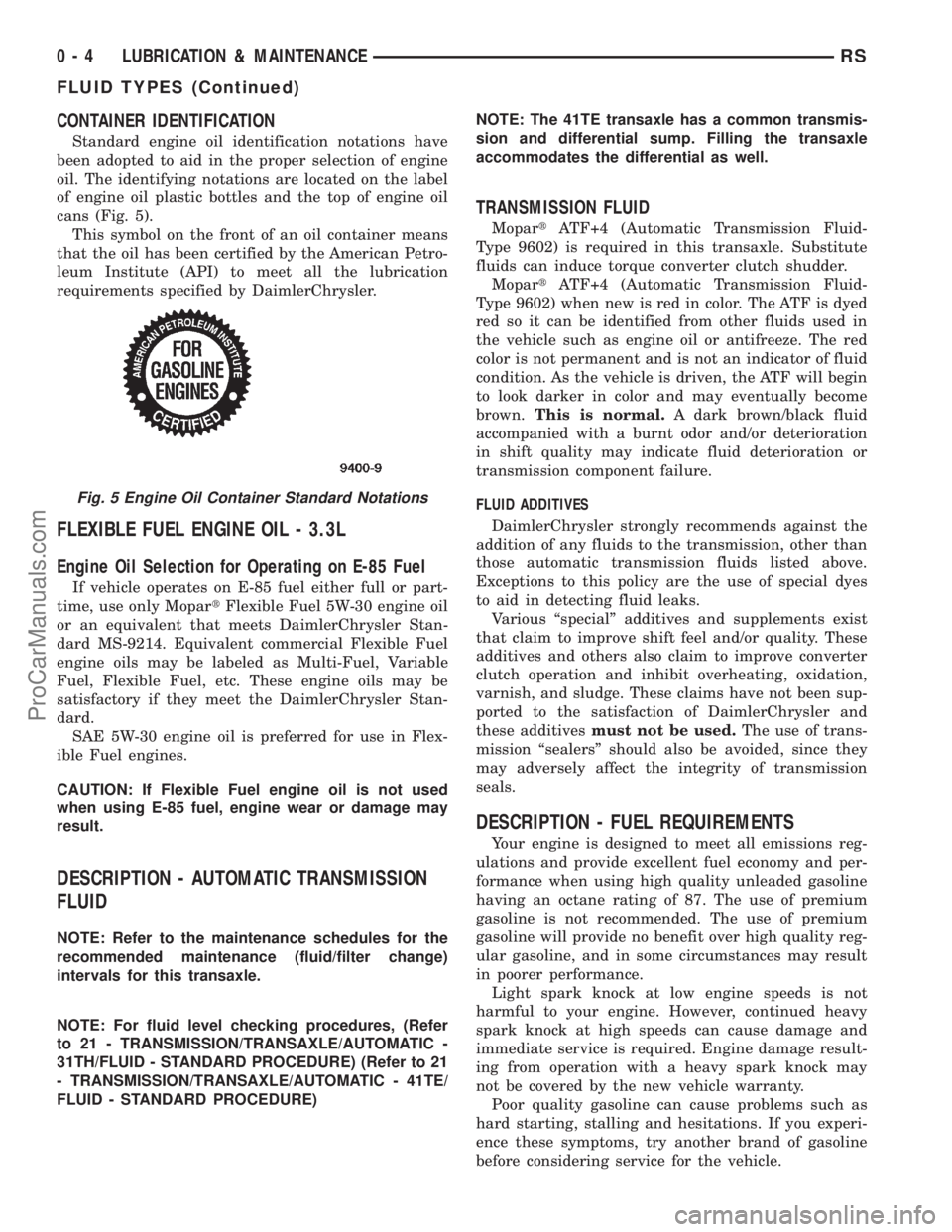
Standard engine oil identification notations have
been adopted to aid in the proper selection of engine
oil. The identifying notations are located on the label
of engine oil plastic bottles and the top of engine oil
cans (Fig. 5).
This symbol on the front of an oil container means
that the oil has been certified by the American Petro-
leum Institute (API) to meet all the lubrication
requirements specified by DaimlerChrysler.
FLEXIBLE FUEL ENGINE OIL - 3.3L
Engine Oil Selection for Operating on E-85 Fuel
If vehicle operates on E-85 fuel either full or part-
time, use only MopartFlexible Fuel 5W-30 engine oil
or an equivalent that meets DaimlerChrysler Stan-
dard MS-9214. Equivalent commercial Flexible Fuel
engine oils may be labeled as Multi-Fuel, Variable
Fuel, Flexible Fuel, etc. These engine oils may be
satisfactory if they meet the DaimlerChrysler Stan-
dard.
SAE 5W-30 engine oil is preferred for use in Flex-
ible Fuel engines.
CAUTION: If Flexible Fuel engine oil is not used
when using E-85 fuel, engine wear or damage may
result.
DESCRIPTION - AUTOMATIC TRANSMISSION
FLUID
NOTE: Refer to the maintenance schedules for the
recommended maintenance (fluid/filter change)
intervals for this transaxle.
NOTE: For fluid level checking procedures, (Refer
to 21 - TRANSMISSION/TRANSAXLE/AUTOMATIC -
31TH/FLUID - STANDARD PROCEDURE) (Refer to 21
- TRANSMISSION/TRANSAXLE/AUTOMATIC - 41TE/
FLUID - STANDARD PROCEDURE)NOTE: The 41TE transaxle has a common transmis-
sion and differential sump. Filling the transaxle
accommodates the differential as well.
TRANSMISSION FLUID
MopartATF+4 (Automatic Transmission Fluid-
Type 9602) is required in this transaxle. Substitute
fluids can induce torque converter clutch shudder.
MopartATF+4 (Automatic Transmission Fluid-
Type 9602) when new is red in color. The ATF is dyed
red so it can be identified from other fluids used in
the vehicle such as engine oil or antifreeze. The red
color is not permanent and is not an indicator of fluid
condition. As the vehicle is driven, the ATF will begin
to look darker in color and may eventually become
brown.This is normal.A dark brown/black fluid
accompanied with a burnt odor and/or deterioration
in shift quality may indicate fluid deterioration or
transmission component failure.
FLUID ADDITIVES
DaimlerChrysler strongly recommends against the
addition of any fluids to the transmission, other than
those automatic transmission fluids listed above.
Exceptions to this policy are the use of special dyes
to aid in detecting fluid leaks.
Various ªspecialº additives and supplements exist
that claim to improve shift feel and/or quality. These
additives and others also claim to improve converter
clutch operation and inhibit overheating, oxidation,
varnish, and sludge. These claims have not been sup-
ported to the satisfaction of DaimlerChrysler and
these additivesmust not be used.The use of trans-
mission ªsealersº should also be avoided, since they
may adversely affect the integrity of transmission
seals.
DESCRIPTION - FUEL REQUIREMENTS
Your engine is designed to meet all emissions reg-
ulations and provide excellent fuel economy and per-
formance when using high quality unleaded gasoline
having an octane rating of 87. The use of premium
gasoline is not recommended. The use of premium
gasoline will provide no benefit over high quality reg-
ular gasoline, and in some circumstances may result
in poorer performance.
Light spark knock at low engine speeds is not
harmful to your engine. However, continued heavy
spark knock at high speeds can cause damage and
immediate service is required. Engine damage result-
ing from operation with a heavy spark knock may
not be covered by the new vehicle warranty.
Poor quality gasoline can cause problems such as
hard starting, stalling and hesitations. If you experi-
ence these symptoms, try another brand of gasoline
before considering service for the vehicle.
Fig. 5 Engine Oil Container Standard Notations
0 - 4 LUBRICATION & MAINTENANCERS
FLUID TYPES (Continued)
ProCarManuals.com
Page 37 of 2321

Inspection and service should also be performed
anytime a malfunction is observed or suspected.
HOISTING
STANDARD PROCEDURE - HOISTING
Refer to Owner's Manual provided with vehicle for
proper emergency jacking procedures.
WARNING: THE HOISTING AND JACK LIFTING
POINTS PROVIDED ARE FOR A COMPLETE VEHI-
CLE. WHEN THE ENGINE OR REAR SUSPENSION
IS REMOVED FROM A VEHICLE, THE CENTER OF
GRAVITY IS ALTERED MAKING SOME HOISTING
CONDITIONS UNSTABLE. PROPERLY SUPPORT OR
SECURE VEHICLE TO HOISTING DEVICE WHEN
THESE CONDITIONS EXIST.
CAUTION: Do not position hoisting device on any
suspension component, including the front suspen-
sion crossmember, the rear leaf springs, and the
rear axle. Do not hoist on the front and rear
bumpers, the lower liftgate crossmember, the lower
radiator crossmember, the down standing flanges
on the sill or the front engine mount.
FOR PROPER HOIST PLACEMENT REFER
TO (Fig. 8).
The hoisting points are identified by S.A.E.
inverted triangle hoisting symbols (Fig. 8). The front
hoisting points are at the bottom of the font rail
below the hoisting symbol approximately 250mm
behind the front suspension crossmember. When
using outboard lift hoists, verify that the hoist lift
pads have been properly adjusted to eliminate con-
tact between the hoist arm and the down standing
flange on the sill. The rear hoisting points are the
leaf spring front mounting brackets. The hoist pad
must be positioned to pick up the flanges on the
bracket, not the leaf spring.
When servicing the leaf springs or the leaf spring
mounting brackets, special provisions are required to
support the rear of the vehicle. Position the rear
hoist pads under the horizontal surface on the bot-
tom of the sill, inboard adjacent to the flange and
centered fore/aft between the jacking indicator tabs
on the lower flange.DO NOT HOIST ON THE
FLANGE.Place a soft pad between the hoist and the
painted surface on the sill to avoid scratching the fin-
ish.
JUMP STARTING
TO JUMP START A DISABLED VEHICLE:
(1) Raise hood on disabled vehicle and visually
inspect engine compartment for:
²Battery cable clamp condition, clean if necessary.
²Frozen battery.
²Yellow or bright color test indicator, if equipped.
²Low battery fluid level.
²Generator drive belt condition and tension.
²Fuel fumes or leakage, correct if necessary.
CAUTION: If the cause of starting problem on dis-
abled vehicle is severe, damage to booster vehicle
charging system can result.
(2) When using another vehicle as a booster
source, park the booster vehicle within cable reach.
Turn off all accessories, set the parking brake, place
the automatic transmission in PARK or the manual
Fig. 8 HOISTING AND JACKING POINTS
1 - DRIVE ON LIFT
2 - FRAME CONTACT LIFT (SINGLE POST)
CHASSIS LIFT (NON-AXLE DUAL POST)
OUTBOARD LIFT (DUAL POST)
FLOOR JACK
3 - S.A.E. HOISTING SYMBOLS
0 - 16 LUBRICATION & MAINTENANCERS
MAINTENANCE SCHEDULES (Continued)
ProCarManuals.com
Page 42 of 2321
LUBRICANTS AND GREASES
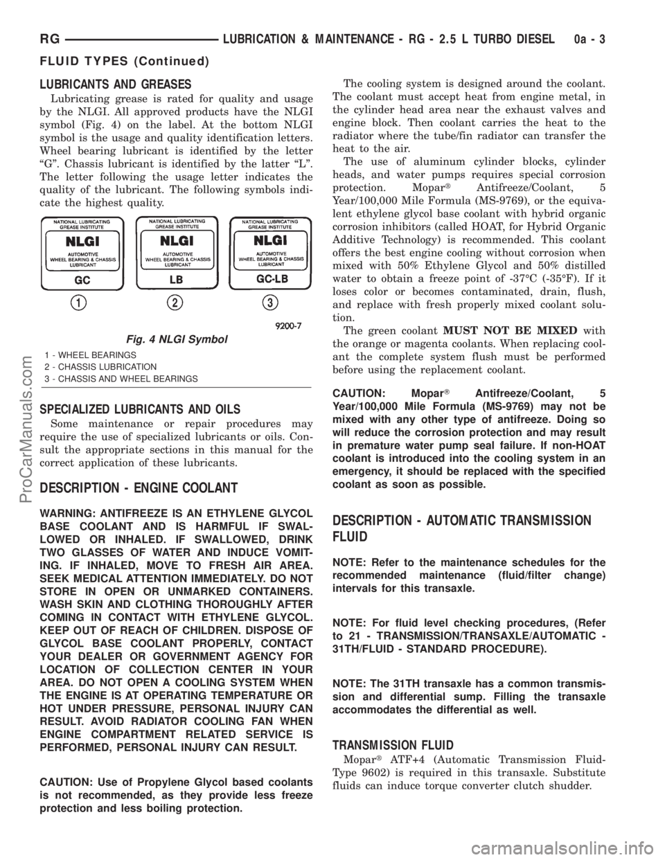
Lubricating grease is rated for quality and usage
by the NLGI. All approved products have the NLGI
symbol (Fig. 4) on the label. At the bottom NLGI
symbol is the usage and quality identification letters.
Wheel bearing lubricant is identified by the letter
ªGº. Chassis lubricant is identified by the latter ªLº.
The letter following the usage letter indicates the
quality of the lubricant. The following symbols indi-
cate the highest quality.
SPECIALIZED LUBRICANTS AND OILS
Some maintenance or repair procedures may
require the use of specialized lubricants or oils. Con-
sult the appropriate sections in this manual for the
correct application of these lubricants.
DESCRIPTION - ENGINE COOLANT
WARNING: ANTIFREEZE IS AN ETHYLENE GLYCOL
BASE COOLANT AND IS HARMFUL IF SWAL-
LOWED OR INHALED. IF SWALLOWED, DRINK
TWO GLASSES OF WATER AND INDUCE VOMIT-
ING. IF INHALED, MOVE TO FRESH AIR AREA.
SEEK MEDICAL ATTENTION IMMEDIATELY. DO NOT
STORE IN OPEN OR UNMARKED CONTAINERS.
WASH SKIN AND CLOTHING THOROUGHLY AFTER
COMING IN CONTACT WITH ETHYLENE GLYCOL.
KEEP OUT OF REACH OF CHILDREN. DISPOSE OF
GLYCOL BASE COOLANT PROPERLY, CONTACT
YOUR DEALER OR GOVERNMENT AGENCY FOR
LOCATION OF COLLECTION CENTER IN YOUR
AREA. DO NOT OPEN A COOLING SYSTEM WHEN
THE ENGINE IS AT OPERATING TEMPERATURE OR
HOT UNDER PRESSURE, PERSONAL INJURY CAN
RESULT. AVOID RADIATOR COOLING FAN WHEN
ENGINE COMPARTMENT RELATED SERVICE IS
PERFORMED, PERSONAL INJURY CAN RESULT.
CAUTION: Use of Propylene Glycol based coolants
is not recommended, as they provide less freeze
protection and less boiling protection.The cooling system is designed around the coolant.
The coolant must accept heat from engine metal, in
the cylinder head area near the exhaust valves and
engine block. Then coolant carries the heat to the
radiator where the tube/fin radiator can transfer the
heat to the air.
The use of aluminum cylinder blocks, cylinder
heads, and water pumps requires special corrosion
protection. MopartAntifreeze/Coolant, 5
Year/100,000 Mile Formula (MS-9769), or the equiva-
lent ethylene glycol base coolant with hybrid organic
corrosion inhibitors (called HOAT, for Hybrid Organic
Additive Technology) is recommended. This coolant
offers the best engine cooling without corrosion when
mixed with 50% Ethylene Glycol and 50% distilled
water to obtain a freeze point of -37ÉC (-35ÉF). If it
loses color or becomes contaminated, drain, flush,
and replace with fresh properly mixed coolant solu-
tion.
The green coolantMUST NOT BE MIXEDwith
the orange or magenta coolants. When replacing cool-
ant the complete system flush must be performed
before using the replacement coolant.
CAUTION: MoparTAntifreeze/Coolant, 5
Year/100,000 Mile Formula (MS-9769) may not be
mixed with any other type of antifreeze. Doing so
will reduce the corrosion protection and may result
in premature water pump seal failure. If non-HOAT
coolant is introduced into the cooling system in an
emergency, it should be replaced with the specified
coolant as soon as possible.DESCRIPTION - AUTOMATIC TRANSMISSION
FLUID
NOTE: Refer to the maintenance schedules for the
recommended maintenance (fluid/filter change)
intervals for this transaxle.
NOTE: For fluid level checking procedures, (Refer
to 21 - TRANSMISSION/TRANSAXLE/AUTOMATIC -
31TH/FLUID - STANDARD PROCEDURE).
NOTE: The 31TH transaxle has a common transmis-
sion and differential sump. Filling the transaxle
accommodates the differential as well.
TRANSMISSION FLUID
MopartATF+4 (Automatic Transmission Fluid-
Type 9602) is required in this transaxle. Substitute
fluids can induce torque converter clutch shudder.
Fig. 4 NLGI Symbol
1 - WHEEL BEARINGS
2 - CHASSIS LUBRICATION
3 - CHASSIS AND WHEEL BEARINGS
RGLUBRICATION & MAINTENANCE - RG - 2.5 L TURBO DIESEL0a-3
FLUID TYPES (Continued)
ProCarManuals.com
Page 47 of 2321
JUMP STARTING
STANDARD PROCEDURE - JUMP STARTING
(1) Raise hood on disabled vehicle and visually
inspect engine compartment for:
²Battery cable clamp condition, clean if necessary.
²Frozen battery.
²Yellow or bright color test indicator, if equipped.
²Low battery fluid level.
²Generator drive belt condition and tension.
²Fuel fumes or leakage, correct if necessary.
CAUTION: If the cause of starting problem on dis-
abled vehicle is severe, damage to booster vehicle
charging system can result.
(2) When using another vehicle as a booster
source, park the booster vehicle within cable reach.
Turn off all accessories, set the parking brake, place
the automatic transmission in PARK or the manual
transmission in NEUTRAL and turn the ignition
OFF.
(3)
On disabled vehicle, place gear selector in park
or neutral and set park brake. Turn off all accessories.
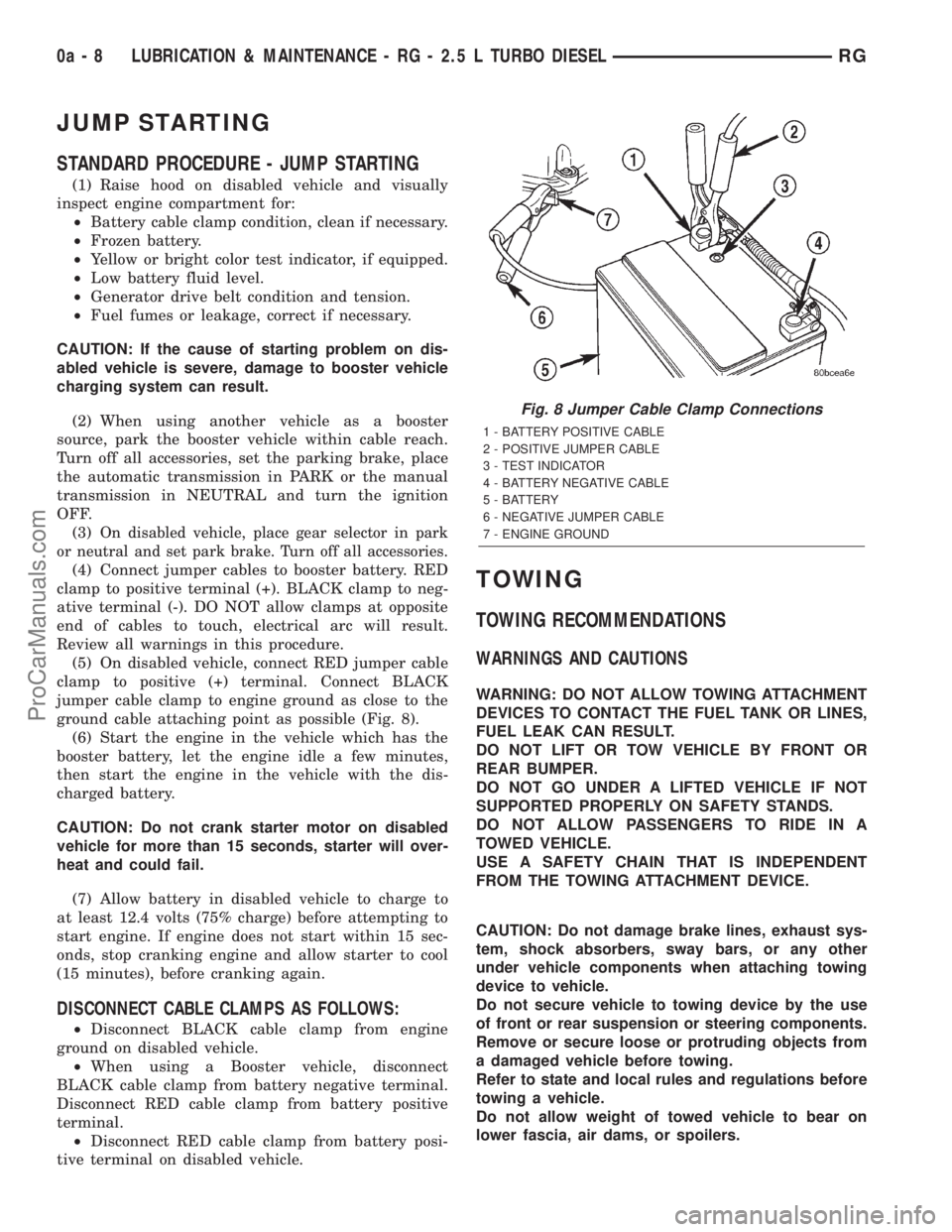
(4) Connect jumper cables to booster battery. RED
clamp to positive terminal (+). BLACK clamp to neg-
ative terminal (-). DO NOT allow clamps at opposite
end of cables to touch, electrical arc will result.
Review all warnings in this procedure.
(5) On disabled vehicle, connect RED jumper cable
clamp to positive (+) terminal. Connect BLACK
jumper cable clamp to engine ground as close to the
ground cable attaching point as possible (Fig. 8).
(6) Start the engine in the vehicle which has the
booster battery, let the engine idle a few minutes,
then start the engine in the vehicle with the dis-
charged battery.
CAUTION: Do not crank starter motor on disabled
vehicle for more than 15 seconds, starter will over-
heat and could fail.
(7) Allow battery in disabled vehicle to charge to
at least 12.4 volts (75% charge) before attempting to
start engine. If engine does not start within 15 sec-
onds, stop cranking engine and allow starter to cool
(15 minutes), before cranking again.
DISCONNECT CABLE CLAMPS AS FOLLOWS:
²Disconnect BLACK cable clamp from engine
ground on disabled vehicle.
²When using a Booster vehicle, disconnect
BLACK cable clamp from battery negative terminal.
Disconnect RED cable clamp from battery positive
terminal.
²Disconnect RED cable clamp from battery posi-
tive terminal on disabled vehicle.
TOWING
TOWING RECOMMENDATIONS
WARNINGS AND CAUTIONS
WARNING: DO NOT ALLOW TOWING ATTACHMENT
DEVICES TO CONTACT THE FUEL TANK OR LINES,
FUEL LEAK CAN RESULT.
DO NOT LIFT OR TOW VEHICLE BY FRONT OR
REAR BUMPER.
DO NOT GO UNDER A LIFTED VEHICLE IF NOT
SUPPORTED PROPERLY ON SAFETY STANDS.
DO NOT ALLOW PASSENGERS TO RIDE IN A
TOWED VEHICLE.
USE A SAFETY CHAIN THAT IS INDEPENDENT
FROM THE TOWING ATTACHMENT DEVICE.
CAUTION: Do not damage brake lines, exhaust sys-
tem, shock absorbers, sway bars, or any other
under vehicle components when attaching towing
device to vehicle.
Do not secure vehicle to towing device by the use
of front or rear suspension or steering components.
Remove or secure loose or protruding objects from
a damaged vehicle before towing.
Refer to state and local rules and regulations before
towing a vehicle.
Do not allow weight of towed vehicle to bear on
lower fascia, air dams, or spoilers.
Fig. 8 Jumper Cable Clamp Connections
1 - BATTERY POSITIVE CABLE
2 - POSITIVE JUMPER CABLE
3 - TEST INDICATOR
4 - BATTERY NEGATIVE CABLE
5 - BATTERY
6 - NEGATIVE JUMPER CABLE
7 - ENGINE GROUND
0a - 8 LUBRICATION & MAINTENANCE - RG - 2.5 L TURBO DIESELRG
ProCarManuals.com
Page 115 of 2321
(7) Install steering knuckle in clevis bracket of
strut damper assembly. Install the strut damper to
steering knuckle attaching bolts. Tighten both bolts
to a torque of 81 N´m (60 ft. lbs.) plus an additional
1/4 turn.
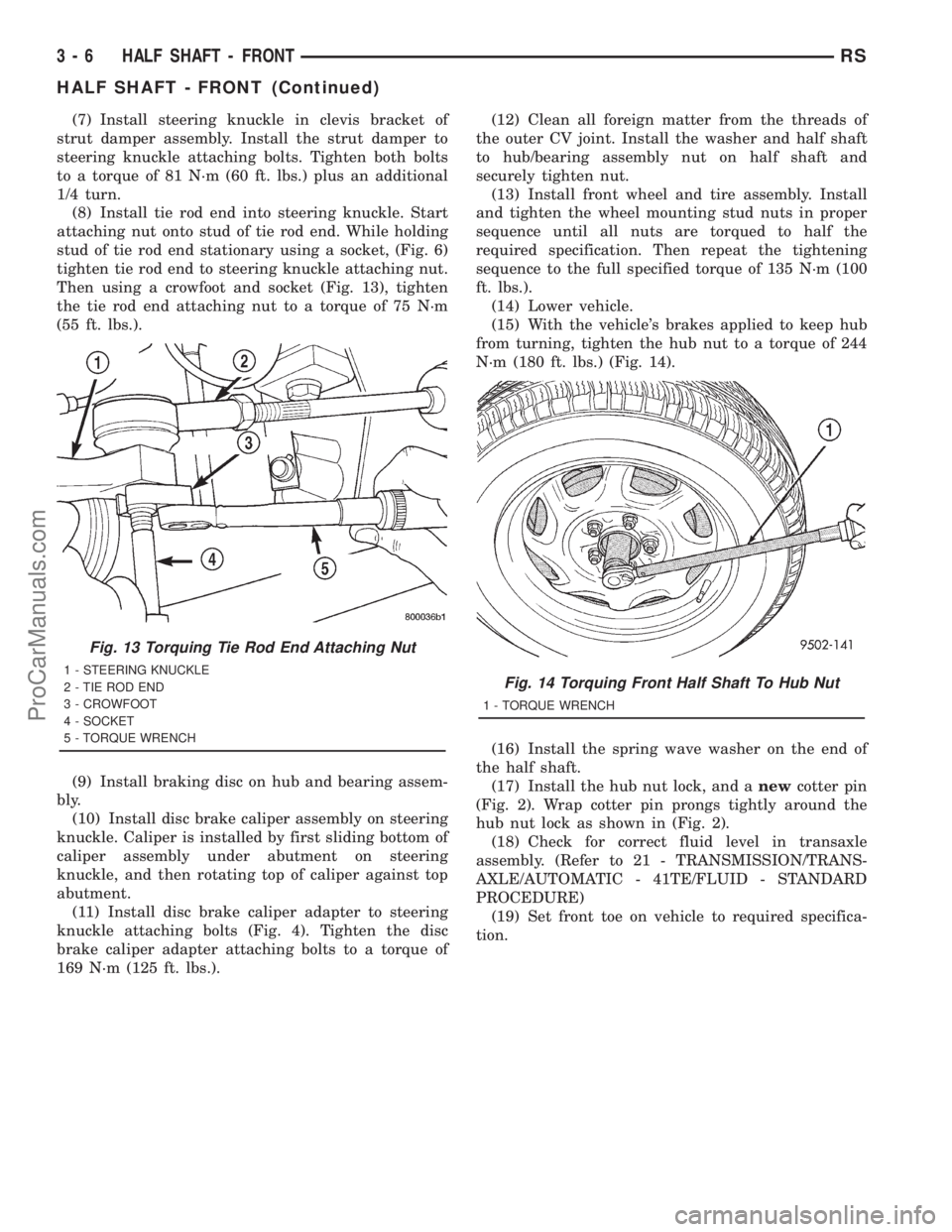
(8) Install tie rod end into steering knuckle. Start
attaching nut onto stud of tie rod end. While holding
stud of tie rod end stationary using a socket, (Fig. 6)
tighten tie rod end to steering knuckle attaching nut.
Then using a crowfoot and socket (Fig. 13), tighten
the tie rod end attaching nut to a torque of 75 N´m
(55 ft. lbs.).
(9) Install braking disc on hub and bearing assem-
bly.
(10) Install disc brake caliper assembly on steering
knuckle. Caliper is installed by first sliding bottom of
caliper assembly under abutment on steering
knuckle, and then rotating top of caliper against top
abutment.
(11) Install disc brake caliper adapter to steering
knuckle attaching bolts (Fig. 4). Tighten the disc
brake caliper adapter attaching bolts to a torque of
169 N´m (125 ft. lbs.).(12) Clean all foreign matter from the threads of
the outer CV joint. Install the washer and half shaft
to hub/bearing assembly nut on half shaft and
securely tighten nut.
(13) Install front wheel and tire assembly. Install
and tighten the wheel mounting stud nuts in proper
sequence until all nuts are torqued to half the
required specification. Then repeat the tightening
sequence to the full specified torque of 135 N´m (100
ft. lbs.).
(14) Lower vehicle.
(15) With the vehicle's brakes applied to keep hub
from turning, tighten the hub nut to a torque of 244
N´m (180 ft. lbs.) (Fig. 14).
(16) Install the spring wave washer on the end of
the half shaft.
(17) Install the hub nut lock, and anewcotter pin
(Fig. 2). Wrap cotter pin prongs tightly around the
hub nut lock as shown in (Fig. 2).
(18) Check for correct fluid level in transaxle
assembly. (Refer to 21 - TRANSMISSION/TRANS-
AXLE/AUTOMATIC - 41TE/FLUID - STANDARD
PROCEDURE)
(19) Set front toe on vehicle to required specifica-
tion.
Fig. 13 Torquing Tie Rod End Attaching Nut
1 - STEERING KNUCKLE
2 - TIE ROD END
3 - CROWFOOT
4 - SOCKET
5 - TORQUE WRENCHFig. 14 Torquing Front Half Shaft To Hub Nut
1 - TORQUE WRENCH
3 - 6 HALF SHAFT - FRONTRS
HALF SHAFT - FRONT (Continued)
ProCarManuals.com
Page 135 of 2321
REAR DRIVELINE MODULE
TABLE OF CONTENTS
page page
REAR DRIVELINE MODULE
DESCRIPTION...........................26
OPERATION.............................26
DIAGNOSIS AND TESTING.................27
REAR DRIVELINE MODULE NOISE.........27
REAR DRIVELINE MODULE OPERATION....29
REMOVAL..............................29
DISASSEMBLY...........................30
ASSEMBLY.............................32
INSTALLATION...........................36
SPECIFICATIONS........................37
SPECIAL TOOLS.........................37
BI-DIRECTIONAL OVERRUNNING CLUTCH
DESCRIPTION...........................37
OPERATION.............................38
DIFFERENTIAL ASSEMBLY
DESCRIPTION...........................43
OPERATION.............................43FLUID - DIFFERENTIAL ASSEMBLY
STANDARD PROCEDURE..................44
DIFFERENTIAL ASSEMBLY FLUID CHANGE . . 44
FLUID
STANDARD PROCEDURE..................44
OVERRUNNING CLUTCH HOUSING FLUID
CHANGE..............................44
VISCOUS COUPLER
DESCRIPTION...........................45
OPERATION.............................45
TORQUE ARM
REMOVAL..............................47
INSTALLATION...........................47
INPUT FLANGE SEAL
REMOVAL..............................47
INSTALLATION...........................47
OUTPUT FLANGE SEAL
REMOVAL..............................49
INSTALLATION...........................50
REAR DRIVELINE MODULE
DESCRIPTION
The rear driveline module assembly (Fig. 1) con-
sists of four main components:
²Bi-Directional Overrunning Clutch (BOC)
²Viscous Coupling
²Differential Assembly
²Torque Arm
The viscous coupling and bi-directional overrun-
ning clutch are contained within an overrunning
clutch housing, which fastens to the differential
assembly. The overrunning clutch housing and differ-
ential assembly have unique fluid sumps, each
requiring their own type and capacity of fluid. The
overrunning clutch housing requires MopartATF+4
(Automatic Transmission FluidÐType 9602) or equiv-
alent. The differential assembly requires
Driveline module service is limited to the following
components:
²Differential Assembly (serviced only as assem-
bly)
²Viscous Coupling
²Bi-Directional Overrunning Clutch (BOC)
²Overrunning Clutch Housing
²Seals (Input Flange, Output Flange, Overrun-
ning Clutch Housing O-rings)
²Input Flange/Shield²Torque Arm
²Vents
²FastenersOPERATION
The primary benefits of All Wheel Drive are:
²Superior straight line acceleration, and corner-
ing on all surfaces
²Better traction and handling under adverse con-
ditions, resulting in improved hill climbing ability
and safer driving.
The heart of the system is an inter-axle viscous
coupling. The vehicle retains predominantly front-
wheel drive characteristics, but the All Wheel Drive
capability takes effect when the front wheels start to
slip. Under normal level road, straight line driving,
100% of the torque is allocated to the front wheels.
The viscous coupling controls and distributes torque/
power to the rear wheels. The viscous coupling trans-
mits torque to the rear wheels in proportion of the
amount of the slippage at the front wheels. Thais
variable torque distribution is automatic with no
driver inputs required. The coupling is similar to a
multi-plate clutch. It consists of a series of closely
spaced discs, which are alternately connected to the
front and rear drive units. The unit is totally sealed
and partially filled with silicone fluid. There is no
3 - 26 REAR DRIVELINE MODULERS
ProCarManuals.com
Page 191 of 2321
STANDARD PROCEDURE - BRAKE FLUID
LEVEL CHECKING
Check master cylinder reservoir fluid level a mini-
mum of twice annually.
Fluid reservoirs are marked with the words FULL
and ADD to indicate proper brake fluid fill level of
the master cylinder.
If necessary, add brake fluid to bring the level to
the bottom of the FULL mark on the side of the mas-
ter cylinder fluid reservoir.
Use only Mopartbrake fluid or equivalent from a
sealed container. Brake fluid must conform to DOT 3
specifications (DOT 4 or DOT 4+ are acceptable).
DO NOTuse brake fluid with a lower boiling
point, as brake failure could result during prolonged
hard braking.
Use only brake fluid that was stored in a tightly-
sealed container.
DO NOTuse petroleum-based fluid because seal
damage will result. Petroleum based fluids would be
items such as engine oil, transmission fluid, power
steering fluid etc.
SPECIFICATIONS
BRAKE FLUID
The brake fluid used in this vehicle must conform
to DOT 3 specifications (DOT 4 and DOT 4+ are
acceptable) and SAE J1703 standards. No other type
of brake fluid is recommended or approved for usage
in the vehicle brake system. Use only MopartBrake
Fluid or equivalent from a tightly sealed container.
CAUTION: Never use reclaimed brake fluid or fluid
from an container which has been left open. An
open container of brake fluid will absorb moisture
from the air and contaminate the fluid.
CAUTION: Never use any type of a petroleum-based
fluid in the brake hydraulic system. Use of such
type fluids will result in seal damage of the vehicle
brake hydraulic system causing a failure of the
vehicle brake system. Petroleum based fluids would
be items such as engine oil, transmission fluid,
power steering fluid, etc.
JUNCTION BLOCK
DESCRIPTION - NON-ABS JUNCTION BLOCK
A junction block is used on vehicles that are not
equipped with antilock brakes (ABS). The junction
block mounts in the same location as the integrated
control unit (ICU) does on vehicles equipped withABS. This allows for use of the same brake tube con-
figuration on all vehicles. The junction block is
located on the driver's side of the front suspension
cradle/crossmember below the master cylinder (Fig.
46).
It has six threaded ports to which the brake tubes
connect. Two are for the primary and secondary
brake tubes coming from the master cylinder. The
remaining four are for the chassis brake tubes going
to each brake assembly.
OPERATION - NON-ABS JUNCTION BLOCK
The junction block distributes the brake fluid com-
ing from the master cylinder primary and secondary
ports to the four chassis brake tubes leading to the
brakes at each wheel. Since the junction block
mounts in the same location as the ABS integrated
control unit (ICU), it allows for the common use of
brake tubes going to the brakes whether the vehicle
is equipped with or without ABS.
NOTE: Although the brake tubes coming from the
master cylinder to the junction block or ABS ICU
may appear to be the same, they are not. They are
unique to each brake system application.
REMOVAL - NON-ABS JUNCTION BLOCK
(1) Using a brake pedal depressor, move and lock
the brake pedal to a position past its first 1 inch of
travel. This will prevent brake fluid from draining
out of the master cylinder when the brake tubes are
removed from the junction block.
(2) Disconnect the battery negative cable.
(3) If the vehicle is equipped with speed control,
perform the following:
(a) Disconnect the battery positive cable.
(b) Remove the battery (Refer to 8 - ELECTRI-
CAL/BATTERY SYSTEM/BATTERY - REMOVAL).
(c) Disconnect the vacuum hose connector at the
tank built into the battery tray.
(d) Remove the screw securing the coolant filler
neck to the battery tray.
(e) Remove the battery tray (Refer to 8 - ELEC-
TRICAL/BATTERY SYSTEM/TRAY - REMOVAL).
(f) Remove the fasteners and move the speed
control servo off to the side, out of the way.
CAUTION: Before removing the brake tubes from
the junction block, the junction block and the brake
tubes must be thoroughly cleaned. This is required
to prevent contamination from entering the brake
hydraulic system.
5 - 32 BRAKES - BASERS
FLUID (Continued)
ProCarManuals.com
Page 304 of 2321
- 31TH/OIL PUMP - STANDARD PROCEDURE)
(Refer to 21 - TRANSMISSION/TRANSAXLE/AU-
TOMATIC - 41TE/OIL PUMP - STANDARD PRO-
CEDURE)
(b) If oil pump volume is within specification, a
possible restriction in the cooler lines or cooler has
occurred.
(c) If oil pump volume is not within specification,
possible internal transmission restrictions, compo-
nent wear or damage has occurred. (Refer to 21 -
TRANSMISSION/TRANSAXLE/AUTOMATIC -
31TH - DIAGNOSIS AND TESTING) (Refer to 21 -
TRANSMISSION/TRANSAXLE/AUTOMATIC -
41TE - DIAGNOSIS AND TESTING)
(d) If an oil cooler restriction is suspected, per-
form further inspections and flow meter testing by
isolating components (i.e. lines, coolers).
(e) After a restriction is isolated, perform cooler
flush procedure. (Refer to 7 - COOLING/TRANS-
MISSION - STANDARD PROCEDURE)
(f) Re-test cooler flow. If cooler flow does not
exceed minimum specification, replace compo-
nent(s) as necessary.
STANDARD PROCEDURE - FLUSHING
COOLERS AND TUBES
The recommended procedure for cooler flushing is
to use Tool 6906 Cooler Flusher.
WARNING:
WEAR PROTECTIVE EYEWEAR THAT MEETS THE
REQUIREMENTS OF OSHA AND ANSI Z87.1±1968.
WEAR STANDARD INDUSTRIAL RUBBER GLOVES.
KEEP LIGHTED CIGARETTES, SPARKS, FLAMES,
AND OTHER IGNITION SOURCES AWAY FROM THE
AREA TO PREVENT THE IGNITION OF COMBUSTI-
BLE LIQUIDS AND GASES. KEEP A CLASS (B) FIRE
EXTINGUISHER IN THE AREA WHERE THE
FLUSHER WILL BE USED.
KEEP THE AREA WELL VENTILATED.
DO NOT LET FLUSHING SOLVENT COME IN CON-
TACT WITH YOUR EYES OR SKIN: IF EYE CONTAM-
INATION OCCURS, FLUSH EYES WITH WATER FOR15 TO 20 SECONDS. REMOVE CONTAMINATED
CLOTHING AND WASH AFFECTED SKIN WITH
SOAP AND WATER. SEEK MEDICAL ATTENTION.
(1) Remove cover plate filler plug on Tool 6906.
Fill reservoir 1/2 to 3/4 full of fresh flushing solution.
Use MopartTransmission Cooler Flush (MS-552) or
equivalent solution conforming to MS-552. Flushing
solvents are petroleum based solutions generally
used to clean automatic transmission components.
DO NOTuse solvents containing acids, water, gaso-
line, or any other corrosive liquids.
(2) Reinstall filler plug on Tool 6906.
(3) Verify pump power switch is turned OFF. Con-
nect red alligator clip to positive (+) battery post.
Connect black (-) alligator clip to a good ground.
NOTE: When flushing transmission cooler and
lines, ALWAYS reverse flush.
(4) Connect the BLUE pressure line to the OUT-
LET (From) cooler line.
(5) Connect the CLEAR return line to the INLET
(To) cooler line
(6) Turn pump ON for two to three minutes to
flush cooler and lines.
(7) Turn pump OFF.
(8) Disconnect CLEAR suction line from reservoir
at cover plate. Disconnect CLEAR return line at
cover plate, and place it in a drain pan.
(9) Turn pump ON for 30 seconds to purge flush-
ing solution from cooler and lines. Turn pump OFF.
(10) Place CLEAR suction line into a one quart
container of MopartATF+4 (Automatic Transmission
FluidÐType 9602).
(11) Turn pump ON until all transmission fluid is
removed from the one quart container and lines. This
purges any residual cleaning solvent from the trans-
mission cooler and lines. Turn pump OFF.
(12) Disconnect alligator clips from battery. Recon-
nect flusher lines to cover plate, and remove flushing
adapters from cooler lines.
RSTRANSMISSION7-37
TRANSMISSION (Continued)
ProCarManuals.com