2001 DODGE TOWN AND COUNTRY torque
[x] Cancel search: torquePage 1187 of 2321
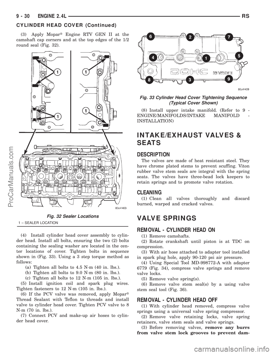
(3) Apply MopartEngine RTV GEN II at the
camshaft cap corners and at the top edges of the 1/2
round seal (Fig. 32).
(4) Install cylinder head cover assembly to cylin-
der head. Install all bolts, ensuring the two (2) bolts
containing the sealing washer are located in the cen-
ter locations of cover. Tighten bolts in sequence
shown in (Fig. 33). Using a 3 step torque method as
follows:
(a) Tighten all bolts to 4.5 N´m (40 in. lbs.).
(b) Tighten all bolts to 9.0 N´m (80 in. lbs.).
(c) Tighten all bolts to 12 N´m (105 in. lbs.).
(5) Install ignition coil and spark plug wires.
Tighten fasteners to 12 N´m (105 in. lbs.).
(6) If the PCV valve was removed, apply Mopart
Thread Sealant with Teflon to threads and install
valve to cylinder head cover. Tighten PCV valve to 8
N´m (70 in. lbs.).
(7) Connect PCV and make-up air hoses to cylin-
der head cover.(8) Install upper intake manifold. (Refer to 9 -
ENGINE/MANIFOLDS/INTAKE MANIFOLD -
INSTALLATION)
INTAKE/EXHAUST VALVES &
SEATS
DESCRIPTION
The valves are made of heat resistant steel. They
have chrome plated stems to prevent scuffing. Viton
rubber valve stem seals are integral with the spring
seats. The valves have three-bead lock keepers to
retain springs and to promote valve rotation.
CLEANING
(1) Clean all valves thoroughly and discard
burned, warped and cracked valves.
VALVE SPRINGS
REMOVAL - CYLINDER HEAD ON
(1) Remove camshafts.
(2) Rotate crankshaft until piston is at TDC on
compression.
(3) With air hose attached to adapter tool installed
in spark plug hole, apply 90-120 psi air pressure.
(4) Using Special Tool MD-998772-A with adapter
6779 (Fig. 34), compress valve springs and remove
valve locks.
(5) Remove valve spring(s).
(6) Remove valve stem seal(s) by a using valve
stem seal tool (Fig. 36).
REMOVAL - CYLINDER HEAD OFF
(1) With cylinder head removed, compress valve
springs using a universal valve spring compressor.
(2) Remove valve retaining locks, valve spring
retainers, valve stem seals and valve springs.
(3) Before removing valves,remove any burrs
from valve stem lock grooves to prevent dam-
Fig. 32 Sealer Locations
1 ± SEALER LOCATION
Fig. 33 Cylinder Head Cover Tightening Sequence
(Typical Cover Shown)
9 - 30 ENGINE 2.4LRS
CYLINDER HEAD COVER (Continued)
ProCarManuals.com
Page 1192 of 2321
(4) A controlled hone motor speed between
200±300 RPM is necessary to obtain the proper cross-
hatch angle. The number of up and down strokes per
minute can be regulated to get the desired 40±60
degree angle. Faster up and down strokes increase
the cross-hatch angle.
(5) After honing, it is necessary that the block be
cleaned again to remove all traces of abrasive.
CAUTION: Ensure all abrasives are removed from
engine parts after honing. It is recommended that a
solution of soap and hot water be used with a
brush and the parts then thoroughly dried. The bore
can be considered clean when it can be wiped
clean with a white cloth and cloth remains clean.
Oil the bores after cleaning to prevent rusting.
CLEANING
Clean cylinder block thoroughly using a suitable
cleaning solvent.
INSPECTION
ENGINE BLOCK
(1) Clean cylinder block thoroughly and check all
core hole plugs for evidence of leaking.
(2) If new core plugs are to be installed, refer to
Engine Core Plugs for procedures (Refer to 9 -
ENGINE - STANDARD PROCEDURE).
(3) Examine block and cylinder bores for cracks or
fractures.
(4) Check block deck surfaces for flatness. Deck
surface must be within service limit of 0.1 mm (0.004
in.).
CYLINDER BORE
NOTE: The cylinder bores should be measured at
normal room temperature, 21ÉC (70ÉF).
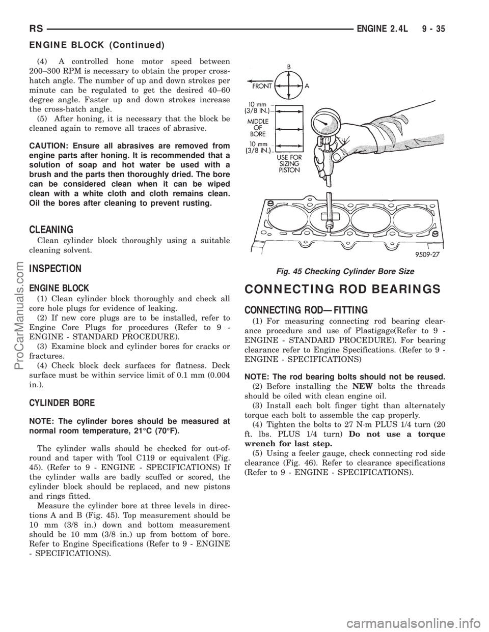
The cylinder walls should be checked for out-of-
round and taper with Tool C119 or equivalent (Fig.
45). (Refer to 9 - ENGINE - SPECIFICATIONS) If
the cylinder walls are badly scuffed or scored, the
cylinder block should be replaced, and new pistons
and rings fitted.
Measure the cylinder bore at three levels in direc-
tions A and B (Fig. 45). Top measurement should be
10 mm (3/8 in.) down and bottom measurement
should be 10 mm (3/8 in.) up from bottom of bore.
Refer to Engine Specifications (Refer to 9 - ENGINE
- SPECIFICATIONS).
CONNECTING ROD BEARINGS
CONNECTING RODÐFITTING
(1) For measuring connecting rod bearing clear-
ance procedure and use of Plastigage(Refer to 9 -
ENGINE - STANDARD PROCEDURE). For bearing
clearance refer to Engine Specifications. (Refer to 9 -
ENGINE - SPECIFICATIONS)
NOTE: The rod bearing bolts should not be reused.
(2) Before installing theNEWbolts the threads
should be oiled with clean engine oil.
(3) Install each bolt finger tight than alternately
torque each bolt to assemble the cap properly.
(4) Tighten the bolts to 27 N´m PLUS 1/4 turn (20
ft. lbs. PLUS 1/4 turn)Do not use a torque
wrench for last step.
(5) Using a feeler gauge, check connecting rod side
clearance (Fig. 46). Refer to clearance specifications
(Refer to 9 - ENGINE - SPECIFICATIONS).
Fig. 45 Checking Cylinder Bore Size
RSENGINE 2.4L9-35
ENGINE BLOCK (Continued)
ProCarManuals.com
Page 1195 of 2321
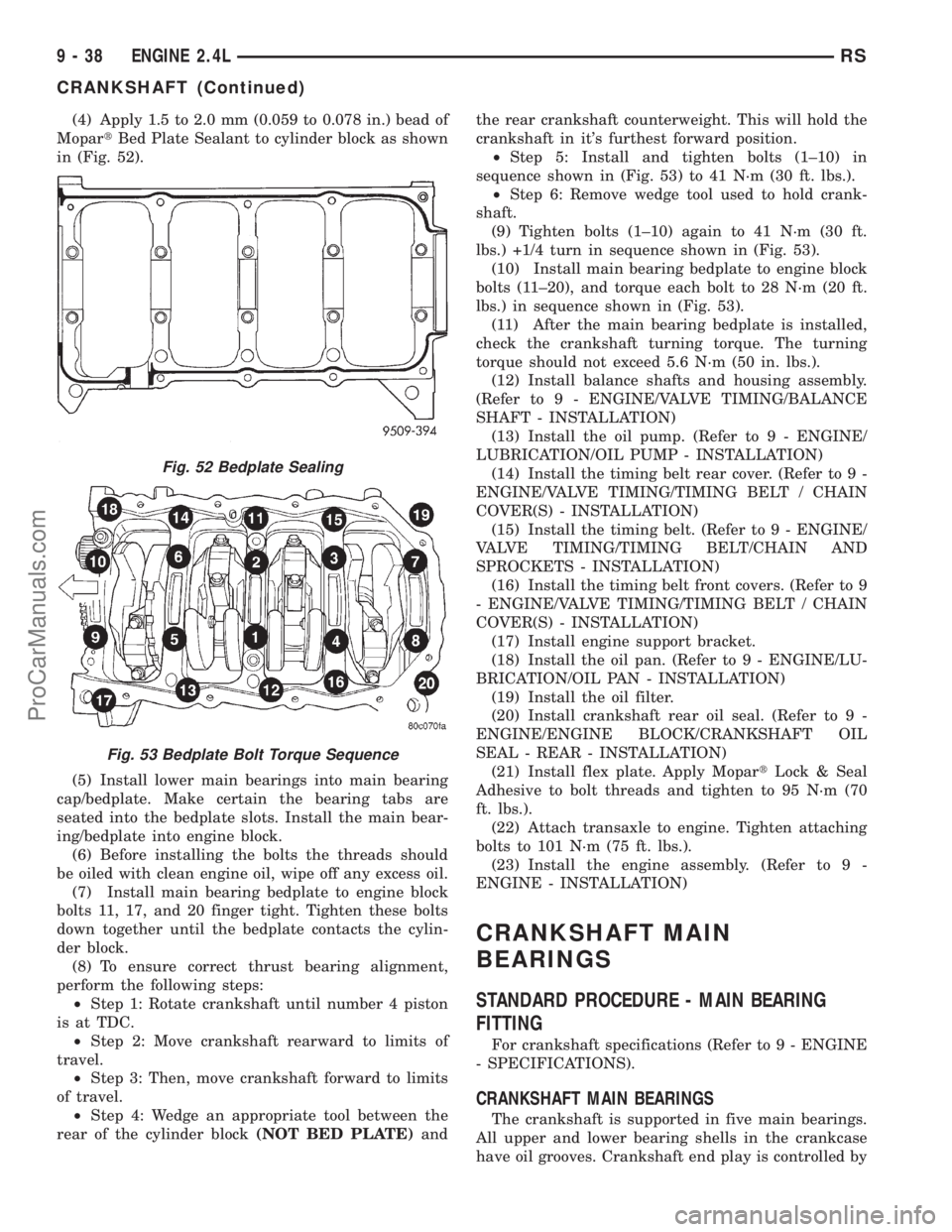
(4) Apply 1.5 to 2.0 mm (0.059 to 0.078 in.) bead of
MopartBed Plate Sealant to cylinder block as shown
in (Fig. 52).
(5) Install lower main bearings into main bearing
cap/bedplate. Make certain the bearing tabs are
seated into the bedplate slots. Install the main bear-
ing/bedplate into engine block.
(6) Before installing the bolts the threads should
be oiled with clean engine oil, wipe off any excess oil.
(7) Install main bearing bedplate to engine block
bolts 11, 17, and 20 finger tight. Tighten these bolts
down together until the bedplate contacts the cylin-
der block.
(8) To ensure correct thrust bearing alignment,
perform the following steps:
²Step 1: Rotate crankshaft until number 4 piston
is at TDC.
²Step 2: Move crankshaft rearward to limits of
travel.
²Step 3: Then, move crankshaft forward to limits
of travel.
²Step 4: Wedge an appropriate tool between the
rear of the cylinder block(NOT BED PLATE)andthe rear crankshaft counterweight. This will hold the
crankshaft in it's furthest forward position.
²Step 5: Install and tighten bolts (1±10) in
sequence shown in (Fig. 53) to 41 N´m (30 ft. lbs.).
²Step 6: Remove wedge tool used to hold crank-
shaft.
(9) Tighten bolts (1±10) again to 41 N´m (30 ft.
lbs.) +1/4 turn in sequence shown in (Fig. 53).
(10) Install main bearing bedplate to engine block
bolts (11±20), and torque each bolt to 28 N´m (20 ft.
lbs.) in sequence shown in (Fig. 53).
(11) After the main bearing bedplate is installed,
check the crankshaft turning torque. The turning
torque should not exceed 5.6 N´m (50 in. lbs.).
(12) Install balance shafts and housing assembly.
(Refer to 9 - ENGINE/VALVE TIMING/BALANCE
SHAFT - INSTALLATION)
(13) Install the oil pump. (Refer to 9 - ENGINE/
LUBRICATION/OIL PUMP - INSTALLATION)
(14) Install the timing belt rear cover. (Refer to 9 -
ENGINE/VALVE TIMING/TIMING BELT / CHAIN
COVER(S) - INSTALLATION)
(15) Install the timing belt. (Refer to 9 - ENGINE/
VALVE TIMING/TIMING BELT/CHAIN AND
SPROCKETS - INSTALLATION)
(16) Install the timing belt front covers. (Refer to 9
- ENGINE/VALVE TIMING/TIMING BELT / CHAIN
COVER(S) - INSTALLATION)
(17) Install engine support bracket.
(18) Install the oil pan. (Refer to 9 - ENGINE/LU-
BRICATION/OIL PAN - INSTALLATION)
(19) Install the oil filter.
(20) Install crankshaft rear oil seal. (Refer to 9 -
ENGINE/ENGINE BLOCK/CRANKSHAFT OIL
SEAL - REAR - INSTALLATION)
(21) Install flex plate. Apply MopartLock & Seal
Adhesive to bolt threads and tighten to 95 N´m (70
ft. lbs.).
(22) Attach transaxle to engine. Tighten attaching
bolts to 101 N´m (75 ft. lbs.).
(23) Install the engine assembly. (Refer to 9 -
ENGINE - INSTALLATION)
CRANKSHAFT MAIN
BEARINGS
STANDARD PROCEDURE - MAIN BEARING
FITTING
For crankshaft specifications (Refer to 9 - ENGINE
- SPECIFICATIONS).
CRANKSHAFT MAIN BEARINGS
The crankshaft is supported in five main bearings.
All upper and lower bearing shells in the crankcase
have oil grooves. Crankshaft end play is controlled by
Fig. 52 Bedplate Sealing
Fig. 53 Bedplate Bolt Torque Sequence
9 - 38 ENGINE 2.4LRS
CRANKSHAFT (Continued)
ProCarManuals.com
Page 1197 of 2321
(5) Install lower main bearings into main bearing
cap/bedplate. Make certain the bearing tabs are
seated into the bedplate slots.
(6) Position the main bearing/bedplate onto the
engine block.
(7) Before installing bolts, lubricate the threads
with clean engine oil, wipe off any excess oil.
(8) Install main bearing bedplate to engine block
bolts 11, 17 and 20 finger tight. Tighten these bolts
down together until the bedplate contacts the cylin-
der block.
(9) To ensure correct thrust bearing alignment,
perform the following steps:
²Step 1: Rotate crankshaft until number 4 piston
is at TDC.
²Step 2: Move crankshaft rearward to limits of
travel.
²Step 3: Then, move crankshaft forward to limits
of travel.
²Step 4: Wedge an appropriate tool between the
rear of the cylinder block(NOT BED PLATE)and
the rear crankshaft counterweight. This will hold the
crankshaft in it's furthest forward position.
²Step 5: Install and tighten bolts (1±10) in
sequence shown in (Fig. 57) to 41 N´m (30 ft. lbs.).
²Step 6: Remove wedge tool used to hold crank-
shaft.
(10) Tighten bolts (1±10) again to 41 N´m (30 ft.
lbs.)PLUS1/4 turn in sequence shown in (Fig. 57).
(11) Install main bearing bedplate to engine block
bolts (11±20), and torque each bolt to 28 N´m (20 ft.
lbs.) in sequence shown in (Fig. 57).
(12) After the main bearing bedplate is installed,
check the crankshaft turning torque. The turning
torque should not exceed 5.6 N´m (50 in. lbs.).
CRANKSHAFT OIL SEAL -
FRONT
REMOVAL
(1) Remove the crankshaft vibration damper.
(Refer to 9 - ENGINE/ENGINE BLOCK/VIBRATION
DAMPER - REMOVAL)
(2) Remove timing belt. (Refer to 9 - ENGINE/
VALVE TIMING/TIMING BELT/CHAIN AND
SPROCKETS - REMOVAL)
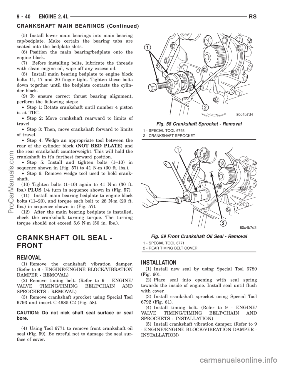
(3) Remove crankshaft sprocket using Special Tool
6793 and insert C-4685-C2 (Fig. 58).
CAUTION: Do not nick shaft seal surface or seal
bore.
(4) Using Tool 6771 to remove front crankshaft oil
seal (Fig. 59). Be careful not to damage the seal sur-
face of cover.INSTALLATION
(1) Install new seal by using Special Tool 6780
(Fig. 60).
(2) Place seal into opening with seal spring
towards the inside of engine. Install seal until flush
with cover.
(3) Install crankshaft sprocket using Special Tool
6792 (Fig. 61).
(4) Install timing belt. (Refer to 9 - ENGINE/
VALVE TIMING/TIMING BELT/CHAIN AND
SPROCKETS - INSTALLATION)
(5) Install crankshaft vibration damper. (Refer to 9
- ENGINE/ENGINE BLOCK/VIBRATION DAMPER -
INSTALLATION)
Fig. 58 Crankshaft Sprocket - Removal
1 - SPECIAL TOOL 6793
2 - CRANKSHAFT SPROCKET
Fig. 59 Front Crankshaft Oil Seal - Removal
1 - SPECIAL TOOL 6771
2 - REAR TIMING BELT COVER
9 - 40 ENGINE 2.4LRS
CRANKSHAFT MAIN BEARINGS (Continued)
ProCarManuals.com
Page 1201 of 2321
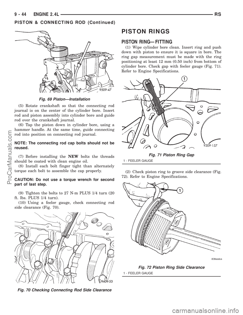
(5) Rotate crankshaft so that the connecting rod
journal is on the center of the cylinder bore. Insert
rod and piston assembly into cylinder bore and guide
rod over the crankshaft journal.
(6) Tap the piston down in cylinder bore, using a
hammer handle. At the same time, guide connecting
rod into position on connecting rod journal.
NOTE: The connecting rod cap bolts should not be
reused.
(7) Before installing theNEWbolts the threads
should be coated with clean engine oil.
(8) Install each bolt finger tight than alternately
torque each bolt to assemble the cap properly.
CAUTION: Do not use a torque wrench for second
part of last step.
(9) Tighten the bolts to 27 N´m PLUS 1/4 turn (20
ft. lbs. PLUS 1/4 turn).
(10) Using a feeler gauge, check connecting rod
side clearance (Fig. 70).
PISTON RINGS
PISTON RINGÐFITTING
(1) Wipe cylinder bore clean. Insert ring and push
down with piston to ensure it is square in bore. The
ring gap measurement must be made with the ring
positioning at least 12 mm (0.50 inch) from bottom of
cylinder bore. Check gap with feeler gauge (Fig. 71).
Refer to Engine Specifications.
(2) Check piston ring to groove side clearance (Fig.
72). Refer to Engine Specifications.
Fig. 69 PistonÐInstallation
Fig. 70 Checking Connecting Rod Side Clearance
Fig. 71 Piston Ring Gap
1 - FEELER GAUGE
Fig. 72 Piston Ring Side Clearance
1 - FEELER GAUGE
9 - 44 ENGINE 2.4LRS
PISTON & CONNECTING ROD (Continued)
ProCarManuals.com
Page 1203 of 2321
VIBRATION DAMPER
REMOVAL
(1) Remove accesory drive belts. (Refer to 7 -
COOLING/ACCESSORY DRIVE/DRIVE BELTS -
REMOVAL)
(2) Remove crankshaft damper bolt.
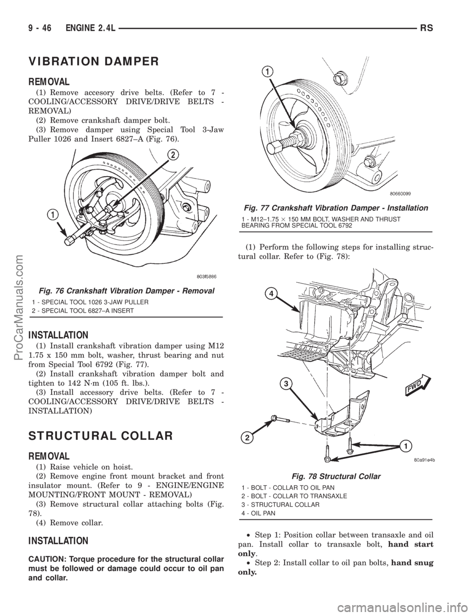
(3) Remove damper using Special Tool 3-Jaw
Puller 1026 and Insert 6827±A (Fig. 76).
INSTALLATION
(1) Install crankshaft vibration damper using M12
1.75 x 150 mm bolt, washer, thrust bearing and nut
from Special Tool 6792 (Fig. 77).
(2) Install crankshaft vibration damper bolt and
tighten to 142 N´m (105 ft. lbs.).
(3) Install accessory drive belts. (Refer to 7 -
COOLING/ACCESSORY DRIVE/DRIVE BELTS -
INSTALLATION)
STRUCTURAL COLLAR
REMOVAL
(1) Raise vehicle on hoist.
(2) Remove engine front mount bracket and front
insulator mount. (Refer to 9 - ENGINE/ENGINE
MOUNTING/FRONT MOUNT - REMOVAL)
(3) Remove structural collar attaching bolts (Fig.
78).
(4) Remove collar.
INSTALLATION
CAUTION: Torque procedure for the structural collar
must be followed or damage could occur to oil pan
and collar.(1) Perform the following steps for installing struc-
tural collar. Refer to (Fig. 78):
²Step 1: Position collar between transaxle and oil
pan. Install collar to transaxle bolt,hand start
only.
²Step 2: Install collar to oil pan bolts,hand snug
only.
Fig. 76 Crankshaft Vibration Damper - Removal
1 - SPECIAL TOOL 1026 3-JAW PULLER
2 - SPECIAL TOOL 6827±A INSERT
Fig. 77 Crankshaft Vibration Damper - Installation
1 - M12±1.753150 MM BOLT, WASHER AND THRUST
BEARING FROM SPECIAL TOOL 6792
Fig. 78 Structural Collar
1 - BOLT - COLLAR TO OIL PAN
2 - BOLT - COLLAR TO TRANSAXLE
3 - STRUCTURAL COLLAR
4 - OIL PAN
9 - 46 ENGINE 2.4LRS
ProCarManuals.com
Page 1204 of 2321
²Step 3: Final torque collar to transaxle bolts to
101 N´m (75 ft. lbs.)
²Step 4: Final torque collar to oil pan bolts to 54
N´m (40 ft. lbs.).
(2) Install engine front mount bracket and insula-
tor. (Refer to 9 - ENGINE/ENGINE MOUNTING/
FRONT MOUNT - INSTALLATION)
(3) Lower vehicle.
ENGINE MOUNTING
DESCRIPTION
The engine mounting system consist of four
mounts; right and a left side support the powertrain,
and a front and a rear mount control powertrain
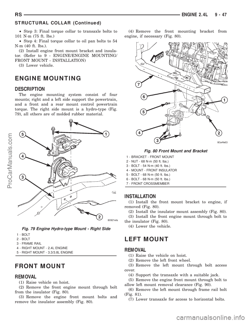
torque. The right side mount is a hydro-type (Fig.
79), all others are of molded rubber material.
FRONT MOUNT
REMOVAL
(1) Raise vehicle on hoist.
(2) Remove the front engine mount through bolt
from the insulator (Fig. 80).
(3) Remove the engine front mount bolts and
remove the insulator assembly (Fig. 80).(4) Remove the front mounting bracket from
engine, if necessary (Fig. 80).
INSTALLATION
(1) Install the front mount bracket to engine, if
removed (Fig. 80).
(2) Install the insulator mount assembly (Fig. 80).
(3) Install the front engine mount through bolt to
the insulator (Fig. 80).
(4) Lower the vehicle.
LEFT MOUNT
REMOVAL
(1) Raise the vehicle on hoist.
(2) Remove the left front wheel.
(3) Remove the left mount through bolt access
cover.
(4) Support the transaxle with a suitable jack.
(5) Remove the engine front mount through bolt to
allow left mount removal clearance (Fig. 90).
(6) Remove the left mount through frame rail bolt
(Fig. 81).
(7) Lower transaxle for access to horizontal bolts.
Fig. 79 Engine Hydro-type Mount - Right Side
1 - BOLT
2 - BOLT
3 - FRAME RAIL
4 - RIGHT MOUNT - 2.4L ENGINE
5 - RIGHT MOUNT - 3.3/3.8L ENGINE
Fig. 80 Front Mount and Bracket
1 - BRACKET - FRONT MOUNT
2 - NUT - 68 N´m (50 ft. lbs.)
3 - BOLT - 54 N´m (40 ft. lbs.)
4 - MOUNT - FRONT INSULATOR
5 - BOLT - 68 N´m (50 ft. lbs.)
6 - BOLT - 68 N´m (50 ft. lbs.)
7 - FRONT CROSSMEMBER
RSENGINE 2.4L9-47
STRUCTURAL COLLAR (Continued)
ProCarManuals.com
Page 1213 of 2321
INTAKE MANIFOLD
DESCRIPTION
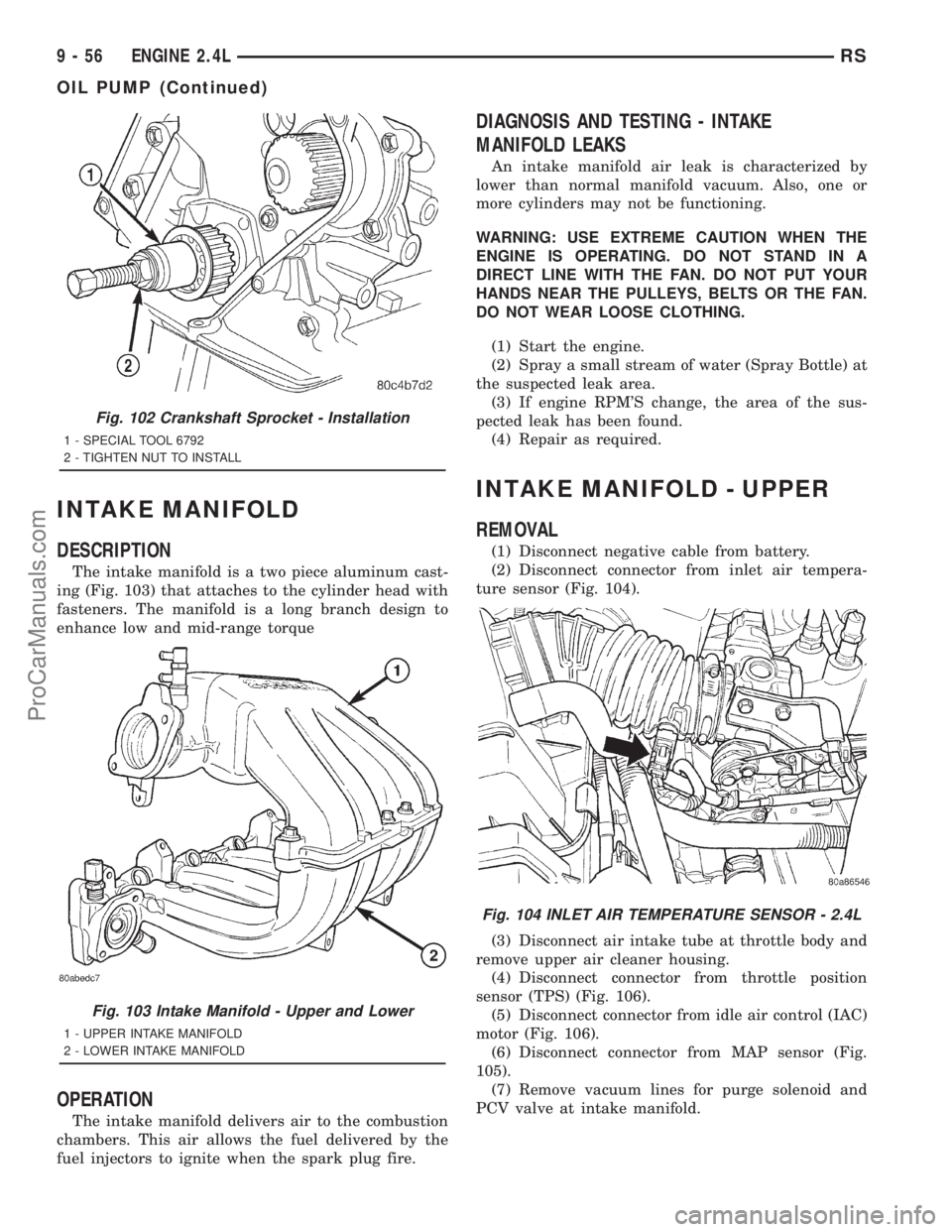
The intake manifold is a two piece aluminum cast-
ing (Fig. 103) that attaches to the cylinder head with
fasteners. The manifold is a long branch design to
enhance low and mid-range torque
OPERATION
The intake manifold delivers air to the combustion
chambers. This air allows the fuel delivered by the
fuel injectors to ignite when the spark plug fire.
DIAGNOSIS AND TESTING - INTAKE
MANIFOLD LEAKS
An intake manifold air leak is characterized by
lower than normal manifold vacuum. Also, one or
more cylinders may not be functioning.
WARNING: USE EXTREME CAUTION WHEN THE
ENGINE IS OPERATING. DO NOT STAND IN A
DIRECT LINE WITH THE FAN. DO NOT PUT YOUR
HANDS NEAR THE PULLEYS, BELTS OR THE FAN.
DO NOT WEAR LOOSE CLOTHING.
(1) Start the engine.
(2) Spray a small stream of water (Spray Bottle) at
the suspected leak area.
(3) If engine RPM'S change, the area of the sus-
pected leak has been found.
(4) Repair as required.
INTAKE MANIFOLD - UPPER
REMOVAL
(1) Disconnect negative cable from battery.
(2) Disconnect connector from inlet air tempera-
ture sensor (Fig. 104).
(3) Disconnect air intake tube at throttle body and
remove upper air cleaner housing.
(4) Disconnect connector from throttle position
sensor (TPS) (Fig. 106).
(5) Disconnect connector from idle air control (IAC)
motor (Fig. 106).
(6) Disconnect connector from MAP sensor (Fig.
105).
(7) Remove vacuum lines for purge solenoid and
PCV valve at intake manifold.
Fig. 102 Crankshaft Sprocket - Installation
1 - SPECIAL TOOL 6792
2 - TIGHTEN NUT TO INSTALL
Fig. 103 Intake Manifold - Upper and Lower
1 - UPPER INTAKE MANIFOLD
2 - LOWER INTAKE MANIFOLD
Fig. 104 INLET AIR TEMPERATURE SENSOR - 2.4L
9 - 56 ENGINE 2.4LRS
OIL PUMP (Continued)
ProCarManuals.com