2001 DODGE TOWN AND COUNTRY check oil
[x] Cancel search: check oilPage 1347 of 2321
STANDARD PROCEDURE - CHECKING
CRANKSHAFT END PLAY
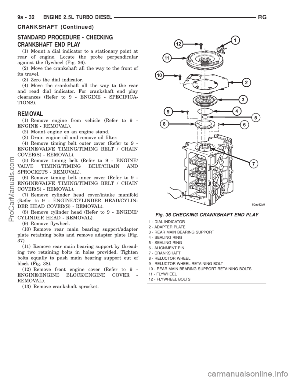
(1) Mount a dial indicator to a stationary point at
rear of engine. Locate the probe perpendicular
against the flywheel (Fig. 36).
(2) Move the crankshaft all the way to the front of
its travel.
(3) Zero the dial indicator.
(4) Move the crankshaft all the way to the rear
and read dial indicator. For crankshaft end play
clearances (Refer to 9 - ENGINE - SPECIFICA-
TIONS).
REMOVAL
(1) Remove engine from vehicle (Refer to 9 -
ENGINE - REMOVAL).
(2) Mount engine on an engine stand.
(3) Drain engine oil and remove oil filter.
(4) Remove timing belt outer cover (Refer to 9 -
ENGINE/VALVE TIMING/TIMING BELT / CHAIN
COVER(S) - REMOVAL).
(5) Remove timing belt (Refer to 9 - ENGINE/
VALVE TIMING/TIMING BELT/CHAIN AND
SPROCKETS - REMOVAL).
(6) Remove timing belt inner cover (Refer to 9 -
ENGINE/VALVE TIMING/TIMING BELT / CHAIN
COVER(S) - REMOVAL).
(7) Remove cylinder head cover/intake manifold
(Refer to 9 - ENGINE/CYLINDER HEAD/CYLIN-
DER HEAD COVER(S) - REMOVAL).
(8) Remove cylinder head (Refer to 9 - ENGINE/
CYLINDER HEAD - REMOVAL).
(9) Remove flywheel.
(10) Remove rear main bearing support/adapter
plate retaining bolts and remove adapter plate (Fig.
37).
(11) Remove rear main bearing support by thread-
ing two retaining bolts in holes provided. Tighten
bolts equally to push main bearing support out of
block (Fig. 38).
(12) Remove front engine cover (Refer to 9 -
ENGINE/ENGINE BLOCK/ENGINE COVER -
REMOVAL).
(13) Remove crankshaft sprocket.
Fig. 36 CHECKING CRANKSHAFT END PLAY
1 - DIAL INDICATOR
2 - ADAPTER PLATE
3 - REAR MAIN BEARING SUPPORT
4 - SEALING RING
5 - SEALING RING
6 - ALIGNMENT PIN
7 - CRANKSHAFT
8 - RELUCTOR WHEEL
9 - RELUCTOR WHEEL RETAINING BOLT
10 - REAR MAIN BEARING SUPPORT RETAINING BOLTS
11 - FLYWHEEL
12 - FLYWHEEL BOLTS
9a - 32 ENGINE 2.5L TURBO DIESELRG
CRANKSHAFT (Continued)
ProCarManuals.com
Page 1349 of 2321
(5) Install front engine cover (Refer to 9 -
ENGINE/ENGINE BLOCK/ENGINE COVER -
INSTALLATION).
(6) Install rear main bearing support in engine
block.Be sure to align oil hole in rear main
bearing support with hole in block.
(7) Install adapter plate and retaining bolts (Fig.
37). Torque bolts to 27.5N´m.
(8) Install flywheel.
(9) Install piston and connecting rod assemblies
(Refer to 9 - ENGINE/ENGINE BLOCK/PISTON &
CONNECTING ROD - INSTALLATION).
(10) Install oil jets (Refer to 9 - ENGINE/LUBRI-
CATION/OIL JET - INSTALLATION).
(11) Install balance shaft assembly (Refer to 9 -
ENGINE/VALVE TIMING/BALANCE SHAFT -
INSTALLATION).
(12) Install oil pump pickup tube (Refer to 9 -
ENGINE/LUBRICATION/OIL PUMP - INSTALLA-
TION).
(13) Install oil pan (Refer to 9 - ENGINE/LUBRI-
CATION/OIL PAN - INSTALLATION).
(14) Install cylinder head (Refer to 9 - ENGINE/
CYLINDER HEAD - INSTALLATION).
(15) Install cylinder head cover/intake manifold
(Refer to 9 - ENGINE/CYLINDER HEAD/CYLIN-
DER HEAD COVER(S) - INSTALLATION).
(16) Install timing belt inner cover (Refer to 9 -
ENGINE/VALVE TIMING/TIMING BELT / CHAIN
COVER(S) - INSTALLATION).
(17) Install timing belt (Refer to 9 - ENGINE/
VALVE TIMING/TIMING BELT/CHAIN AND
SPROCKETS - INSTALLATION) .(18) Install timing belt outer cover (Refer to 9 -
ENGINE/VALVE TIMING/TIMING BELT / CHAIN
COVER(S) - INSTALLATION).
(19) Install engine in vehicle.
(20) Fill engine oil with proper oil to correct level.
CYLINDER LINERS
DESCRIPTION
The cylinder wall liner used on this engine is of
the wet design. O-rings are used to seal the liner to
the engine block.
REMOVAL
(1) Remove engine from vehicle.
(2) With engine completely disassembled, use spe-
cial tool VM.1001 to remove liner assembly (Fig. 41).
(3) Tighten bolt on VM.1001 to remove liner from
block (Fig. 42).
(4) Remove shims from cylinder liner or cylinder
block recess. Keep shims with each cylinder liner.
INSPECTION
The cylinder walls should be checked for out-of-
round and taper with a dial bore gauge. The cylinder
bore out-of-round is 0.100 mm (.0039 in.) maximum
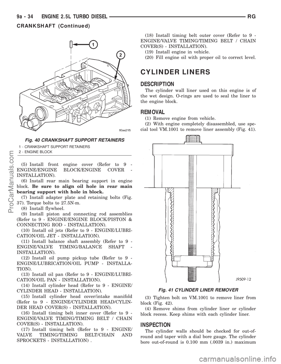
Fig. 40 CRANKSHAFT SUPPORT RETAINERS
1 - CRANKSHAFT SUPPORT RETAINERS
2 - ENGINE BLOCK
Fig. 41 CYLINDER LINER REMOVER
9a - 34 ENGINE 2.5L TURBO DIESELRG
CRANKSHAFT (Continued)
ProCarManuals.com
Page 1353 of 2321
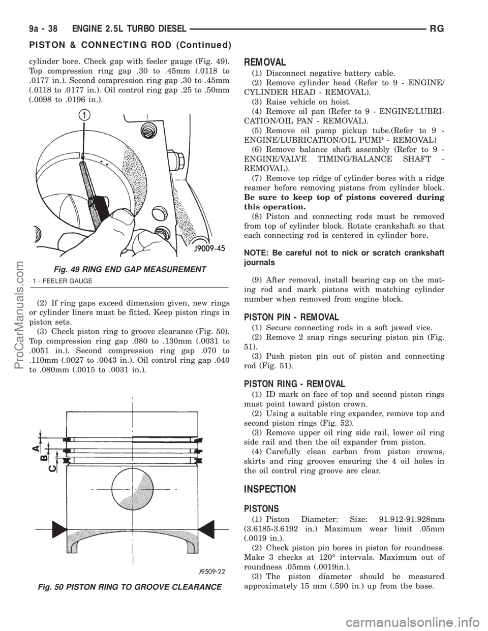
cylinder bore. Check gap with feeler gauge (Fig. 49).
Top compression ring gap .30 to .45mm (.0118 to
.0177 in.). Second compression ring gap .30 to .45mm
(.0118 to .0177 in.). Oil control ring gap .25 to .50mm
(.0098 to .0196 in.).
(2) If ring gaps exceed dimension given, new rings
or cylinder liners must be fitted. Keep piston rings in
piston sets.
(3) Check piston ring to groove clearance (Fig. 50).
Top compression ring gap .080 to .130mm (.0031 to
.0051 in.). Second compression ring gap .070 to
.110mm (.0027 to .0043 in.). Oil control ring gap .040
to .080mm (.0015 to .0031 in.).REMOVAL
(1) Disconnect negative battery cable.
(2) Remove cylinder head (Refer to 9 - ENGINE/
CYLINDER HEAD - REMOVAL).
(3) Raise vehicle on hoist.
(4) Remove oil pan (Refer to 9 - ENGINE/LUBRI-
CATION/OIL PAN - REMOVAL).
(5) Remove oil pump pickup tube.(Refer to 9 -
ENGINE/LUBRICATION/OIL PUMP - REMOVAL)
(6) Remove balance shaft assembly (Refer to 9 -
ENGINE/VALVE TIMING/BALANCE SHAFT -
REMOVAL).
(7) Remove top ridge of cylinder bores with a ridge
reamer before removing pistons from cylinder block.
Be sure to keep top of pistons covered during
this operation.
(8) Piston and connecting rods must be removed
from top of cylinder block. Rotate crankshaft so that
each connecting rod is centered in cylinder bore.
NOTE: Be careful not to nick or scratch crankshaft
journals
(9) After removal, install bearing cap on the mat-
ing rod and mark pistons with matching cylinder
number when removed from engine block.
PISTON PIN - REMOVAL
(1) Secure connecting rods in a soft jawed vice.
(2) Remove 2 snap rings securing piston pin (Fig.
51).
(3) Push piston pin out of piston and connecting
rod (Fig. 51).
PISTON RING - REMOVAL
(1) ID mark on face of top and second piston rings
must point toward piston crown.
(2) Using a suitable ring expander, remove top and
second piston rings (Fig. 52).
(3) Remove upper oil ring side rail, lower oil ring
side rail and then the oil expander from piston.
(4) Carefully clean carbon from piston crowns,
skirts and ring grooves ensuring the 4 oil holes in
the oil control ring groove are clear.
INSPECTION
PISTONS
(1) Piston Diameter: Size: 91.912-91.928mm
(3.6185-3.6192 in.) Maximum wear limit .05mm
(.0019 in.).
(2) Check piston pin bores in piston for roundness.
Make 3 checks at 120É intervals. Maximum out of
roundness .05mm (.0019in.).
(3) The piston diameter should be measured
approximately 15 mm (.590 in.) up from the base.
Fig. 49 RING END GAP MEASUREMENT
1 - FEELER GAUGE
Fig. 50 PISTON RING TO GROOVE CLEARANCE
9a - 38 ENGINE 2.5L TURBO DIESELRG
PISTON & CONNECTING ROD (Continued)
ProCarManuals.com
Page 1355 of 2321
PISTON PINS
(1) Measure the diameter of piston pin in the cen-
ter and both ends.
(2) Piston pin diameter is 29.992 to 29.996mm
(1.1807 to 1.1809 in.).
INSTALLATION
PISTON PIN INSTALLATION
(1) Secure connecting rod in soft jawed vice.
(2) Lubricate piston pin and piston with clean
engine oil.
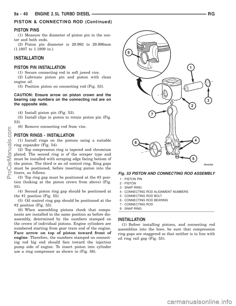
(3) Position piston on connecting rod (Fig. 53).
CAUTION: Ensure arrow on piston crown and the
bearing cap numbers on the connecting rod are on
the opposite side.
(4) Install piston pin (Fig. 53).
(5) Install clips in piston to retain piston pin (Fig.
53).
(6) Remove connecting rod from vice.
PISTON RINGS - INSTALLATION
(1) Install rings on the pistons using a suitable
ring expander (Fig. 54).
(2) Top compression ring is tapered and chromium
plated. The second ring is of the scraper type and
must be installed with scraping edge facing bottom of
the piston. The third is an oil control ring. Ring gaps
must be positioned, before inserting piston into the
liners, as follows.
(3) Top ring gap must be positioned at the #3 posi-
tion (looking at the piston crown from above) (Fig.
55).
(4) Second piston ring gap should be positioned at
the #1 position (Fig. 55).
(5) Oil control ring gap should be positioned at the
#2 position (Fig. 55).
(6) When assembling pistons check that compo-
nents are installed in the same position as before dis-
assembly, determined by the numbers stamped on
the crown of individual pistons. Engine cylinders are
numbered starting from gear train end of the engine.
Face arrow on top of piston toward front of
engine. Therefore, the numbers stamped on connect-
ing rod big end should face toward the injection
pump side of engine. To insert piston into cylinder
use a ring compressor as shown in (Fig. 56).
INSTALLATION
(1) Before installing pistons, and connecting rod
assemblies into the bore, be sure that compression
ring gaps are staggered so that neither is in line with
oil ring rail gap (Fig. 55).
Fig. 53 PISTON AND CONNECTING ROD ASSEMBLY
1 - PISTON PIN
2 - PISTON
3 - SNAP RING
4 - CONNECTING ROD ALIGNMENT NUMBERS
5 - CONNECTING ROD BOLT
6 - CONNECTING ROD BEARING
7 - CONNECTING ROD
8 - SNAP RING
9a - 40 ENGINE 2.5L TURBO DIESELRG
PISTON & CONNECTING ROD (Continued)
ProCarManuals.com
Page 1365 of 2321
INSTALLATION
(1) Apply MopartThread Sealant to the switch
threads.
(2) Install oil pressure switch in engine block.
(3) Connect oil pressure switch electrical connector
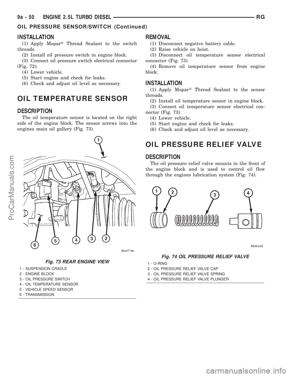
(Fig. 72).
(4) Lower vehicle.
(5) Start engine and check for leaks.
(6) Check and adjust oil level as necessary.
OIL TEMPERATURE SENSOR
DESCRIPTION
The oil temperature sensor is located on the right
side of the engine block. The sensor screws into the
engines main oil gallery (Fig. 73).
REMOVAL
(1) Disconnect negative battery cable.
(2) Raise vehicle on hoist.
(3) Disconnect oil temperature sensor electrical
connector (Fig. 73).
(4) Remove oil temperature sensor from engine
block.
INSTALLATION
(1) Apply MopartThread Sealant to the sensor
threads.
(2) Install oil temperature sensor in engine block.
(3) Connect oil temperature sensor electrical con-
nector (Fig. 73)
(4) Lower vehicle.
(5) Start engine and check for leaks.
(6) Check and adjust oil level as necessary.
OIL PRESSURE RELIEF VALVE
DESCRIPTION
The oil pressure relief valve mounts in the front of
the engine block and is used to control oil flow
through the engines lubrication system (Fig. 74).
Fig. 73 REAR ENGINE VIEW
1 - SUSPENSION CRADLE
2 - ENGINE BLOCK
3 - OIL PRESSURE SWITCH
4 - OIL TEMPERATURE SENSOR
5 - VEHICLE SPEED SENSOR
6 - TRANSMISSION
Fig. 74 OIL PRESSURE RELIEF VALVE
1 - O-RING
2 - OIL PRESSURE RELIEF VALVE CAP
3 - OIL PRESSURE RELIEF VALVE SPRING
4 - OIL PRESSURE RELIEF VALVE PLUNGER
9a - 50 ENGINE 2.5L TURBO DIESELRG
OIL PRESSURE SENSOR/SWITCH (Continued)
ProCarManuals.com
Page 1367 of 2321
(7) Remove oil cooler retaining stud and remove oil
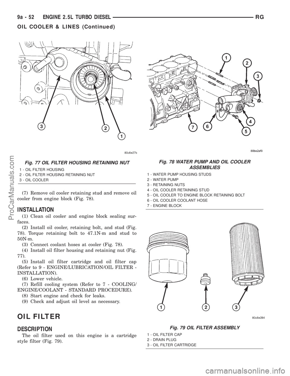
cooler from engine block (Fig. 78).
INSTALLATION
(1) Clean oil cooler and engine block sealing sur-
faces.
(2) Install oil cooler, retaining bolt, and stud (Fig.
78). Torque retaining bolt to 47.1N´m and stud to
50N´m.
(3) Connect coolant hoses at cooler (Fig. 78).
(4) Install oil filter housing and retaining nut (Fig.
77).
(5) Install oil filter cartridge and oil filter cap
(Refer to 9 - ENGINE/LUBRICATION/OIL FILTER -
INSTALLATION).
(6) Lower vehicle.
(7) Refill cooling system (Refer to 7 - COOLING/
ENGINE/COOLANT - STANDARD PROCEDURE).
(8) Start engine and check for leaks.
(9) Check and adjust oil level as necessary.
OIL FILTER
DESCRIPTION
The oil filter used on this engine is a cartridge
style filter (Fig. 79).
Fig. 77 OIL FILTER HOUSING RETAINING NUT
1 - OIL FILTER HOUSING
2 - OIL FILTER HOUSING RETAINING NUT
3 - OIL COOLER
Fig. 78 WATER PUMP AND OIL COOLER
ASSEMBLIES
1 - WATER PUMP HOUSING STUDS
2 - WATER PUMP
3 - RETAINING NUTS
4 - OIL COOLER RETAINING STUD
5 - OIL COOLER TO ENGINE BLOCK RETAINING BOLT
6 - OIL COOLER COOLANT HOSE
7 - ENGINE BLOCK
Fig. 79 OIL FILTER ASSEMBLY
1 - OIL FILTER CAP
2 - DRAIN PLUG
3 - OIL FILTER CARTRIDGE
9a - 52 ENGINE 2.5L TURBO DIESELRG
OIL COOLER & LINES (Continued)
ProCarManuals.com
Page 1368 of 2321
REMOVAL
(1) Raise vehicle on hoist.
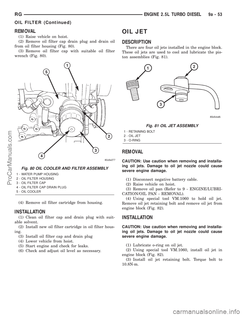
(2) Remove oil filter cap drain plug and drain oil
from oil filter housing (Fig. 80).
(3) Remove oil filter cap with suitable oil filter
wrench (Fig. 80).
(4) Remove oil filter cartridge from housing.
INSTALLATION
(1) Clean oil filter cap and drain plug with suit-
able solvent.
(2) Install new oil filter cartridge in oil filter hous-
ing.
(3) Install oil filter cap and drain plug
(4) Lower vehicle from hoist.
(5) Start engine and check for leaks.
(6) Check and adjust oil level as necessary.
OIL JET
DESCRIPTION
There are four oil jets installed in the engine block.
These oil jets are used to cool and lubricate the pis-
ton assemblies (Fig. 81).
REMOVAL
CAUTION: Use caution when removing and installa-
ing oil jets. Damage to oil jet nozzle could cause
severe engine damage.
(1) Disconnect negative battery cable.
(2) Raise vehicle on hoist.
(3) Remove oil pan (Refer to 9 - ENGINE/LUBRI-
CATION/OIL PAN - REMOVAL).
(4) Using special tool VM.1060 to hold oil jet.
Remove oil jet retaining bolt and remove oil jet from
engine block (Fig. 82).
INSTALLATION
CAUTION: Use caution when removing and installa-
ing oil jets. Damage to oil jet nozzle could cause
severe engine damage.
(1) Lubricate o-ring on oil jet.
(2) Using special tool VM.1060, install oil jet in
engine block (Fig. 82).
(3) Install oil jet retaining bolt. Torque bolt to
10.8N´m.
Fig. 80 OIL COOLER AND FILTER ASSEMBLY
1 - WATER PUMP HOUSING
2 - OIL FILTER HOUSING
3 - OIL FILTER CAP
4 - OIL FILTER CAP DRAIN PLUG
5 - OIL COOLER
Fig. 81 OIL JET ASSEMBLY
1 - RETAINING BOLT
2 - OIL JET
3 - O-RING
RGENGINE 2.5L TURBO DIESEL9a-53
OIL FILTER (Continued)
ProCarManuals.com
Page 1412 of 2321
The pressure regulator is a mechanical device that
is NOT controlled by the PCM or engine vacuum.
REMOVAL
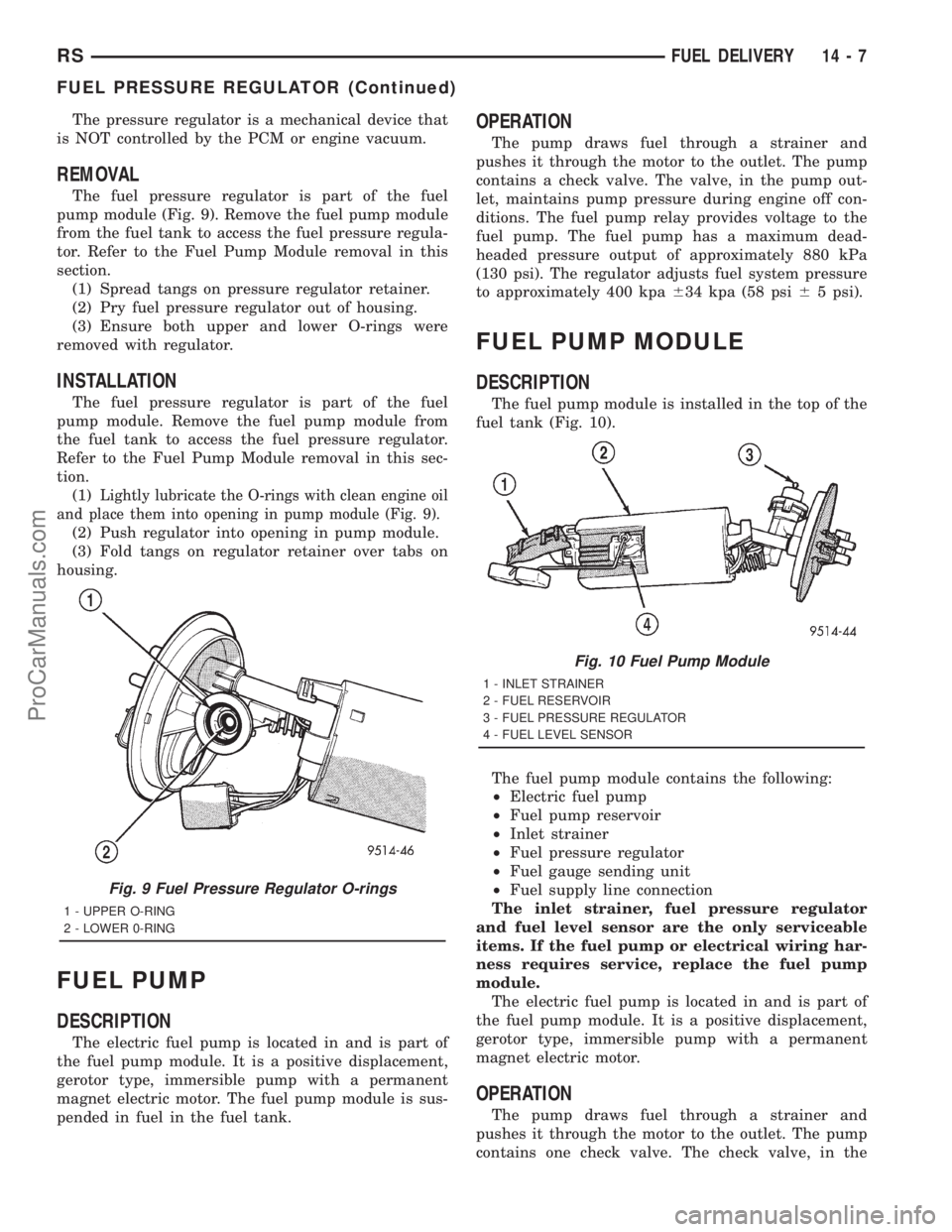
The fuel pressure regulator is part of the fuel
pump module (Fig. 9). Remove the fuel pump module
from the fuel tank to access the fuel pressure regula-
tor. Refer to the Fuel Pump Module removal in this
section.
(1) Spread tangs on pressure regulator retainer.
(2) Pry fuel pressure regulator out of housing.
(3) Ensure both upper and lower O-rings were
removed with regulator.
INSTALLATION
The fuel pressure regulator is part of the fuel
pump module. Remove the fuel pump module from
the fuel tank to access the fuel pressure regulator.
Refer to the Fuel Pump Module removal in this sec-
tion.
(1)
Lightly lubricate the O-rings with clean engine oil
and place them into opening in pump module (Fig. 9).
(2) Push regulator into opening in pump module.
(3) Fold tangs on regulator retainer over tabs on
housing.
FUEL PUMP
DESCRIPTION
The electric fuel pump is located in and is part of
the fuel pump module. It is a positive displacement,
gerotor type, immersible pump with a permanent
magnet electric motor. The fuel pump module is sus-
pended in fuel in the fuel tank.
OPERATION
The pump draws fuel through a strainer and
pushes it through the motor to the outlet. The pump
contains a check valve. The valve, in the pump out-
let, maintains pump pressure during engine off con-
ditions. The fuel pump relay provides voltage to the
fuel pump. The fuel pump has a maximum dead-
headed pressure output of approximately 880 kPa
(130 psi). The regulator adjusts fuel system pressure
to approximately 400 kpa634 kpa (58 psi65 psi).
FUEL PUMP MODULE
DESCRIPTION
The fuel pump module is installed in the top of the
fuel tank (Fig. 10).
The fuel pump module contains the following:
²Electric fuel pump
²Fuel pump reservoir
²Inlet strainer
²Fuel pressure regulator
²Fuel gauge sending unit
²Fuel supply line connection
The inlet strainer, fuel pressure regulator
and fuel level sensor are the only serviceable
items. If the fuel pump or electrical wiring har-
ness requires service, replace the fuel pump
module.
The electric fuel pump is located in and is part of
the fuel pump module. It is a positive displacement,
gerotor type, immersible pump with a permanent
magnet electric motor.
OPERATION
The pump draws fuel through a strainer and
pushes it through the motor to the outlet. The pump
contains one check valve. The check valve, in the
Fig. 9 Fuel Pressure Regulator O-rings
1 - UPPER O-RING
2 - LOWER 0-RING
Fig. 10 Fuel Pump Module
1 - INLET STRAINER
2 - FUEL RESERVOIR
3 - FUEL PRESSURE REGULATOR
4 - FUEL LEVEL SENSOR
RSFUEL DELIVERY14-7
FUEL PRESSURE REGULATOR (Continued)
ProCarManuals.com