2001 DODGE TOWN AND COUNTRY check oil
[x] Cancel search: check oilPage 1514 of 2321
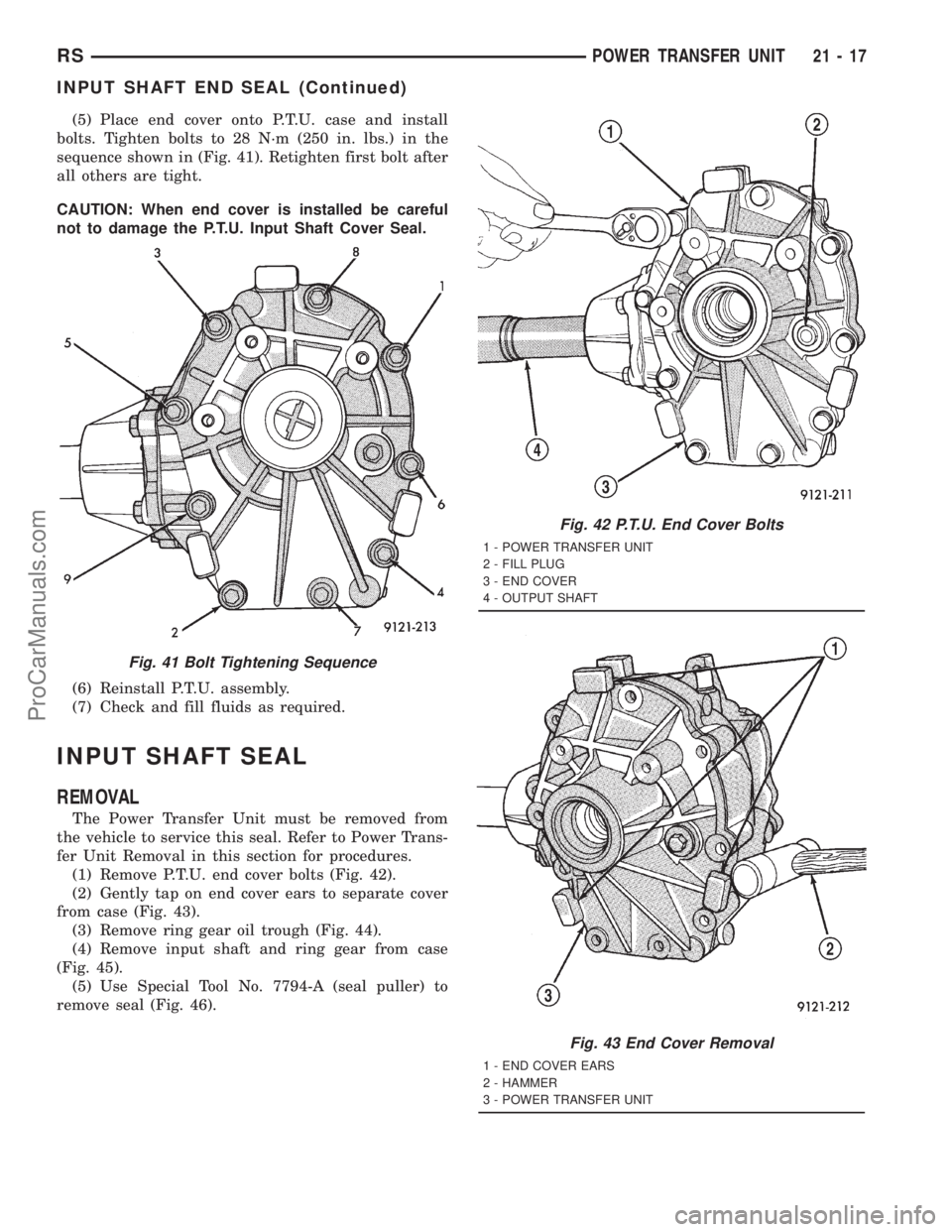
(5) Place end cover onto P.T.U. case and install
bolts. Tighten bolts to 28 N´m (250 in. lbs.) in the
sequence shown in (Fig. 41). Retighten first bolt after
all others are tight.
CAUTION: When end cover is installed be careful
not to damage the P.T.U. Input Shaft Cover Seal.
(6) Reinstall P.T.U. assembly.
(7) Check and fill fluids as required.
INPUT SHAFT SEAL
REMOVAL
The Power Transfer Unit must be removed from
the vehicle to service this seal. Refer to Power Trans-
fer Unit Removal in this section for procedures.
(1) Remove P.T.U. end cover bolts (Fig. 42).
(2) Gently tap on end cover ears to separate cover
from case (Fig. 43).
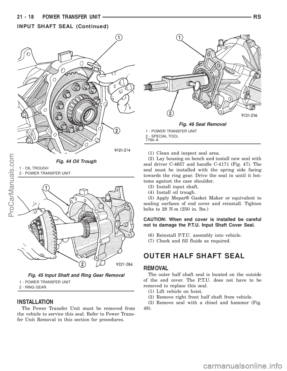
(3) Remove ring gear oil trough (Fig. 44).
(4) Remove input shaft and ring gear from case
(Fig. 45).
(5) Use Special Tool No. 7794-A (seal puller) to
remove seal (Fig. 46).
Fig. 41 Bolt Tightening Sequence
Fig. 42 P.T.U. End Cover Bolts
1 - POWER TRANSFER UNIT
2 - FILL PLUG
3 - END COVER
4 - OUTPUT SHAFT
Fig. 43 End Cover Removal
1 - END COVER EARS
2 - HAMMER
3 - POWER TRANSFER UNIT
RSPOWER TRANSFER UNIT21-17
INPUT SHAFT END SEAL (Continued)
ProCarManuals.com
Page 1515 of 2321
INSTALLATION
The Power Transfer Unit must be removed from
the vehicle to service this seal. Refer to Power Trans-
fer Unit Removal in this section for procedures.(1) Clean and inspect seal area.
(2) Lay housing on bench and install new seal with
seal driver C-4657 and handle C-4171 (Fig. 47). The
seal must be installed with the spring side facing
towards the ring gear. Drive the seal in until it bot-
toms against the case shoulder.
(3) Install input shaft.
(4) Install oil trough.
(5) Apply Moparž Gasket Maker or equivalent to
sealing surfaces of end cover and reinstall. Tighten
bolts to 28 N´m (250 in. lbs.)
CAUTION: When end cover is installed be careful
not to damage the P.T.U. Input Shaft Cover Seal.
(6) Reinstall P.T.U. assembly into vehicle.
(7) Check and fill fluids as required.
OUTER HALF SHAFT SEAL
REMOVAL
The outer half shaft seal is located on the outside
of the end cover. The P.T.U. does not have to be
removed to replace this seal.
(1) Lift vehicle on hoist.
(2) Remove right front half shaft from vehicle.
(3) Remove seal with a chisel and hammer (Fig.
48).
Fig. 44 Oil Trough
1 - OIL TROUGH
2 - POWER TRANSFER UNIT
Fig. 45 Input Shaft and Ring Gear Removal
1 - POWER TRANSFER UNIT
2 - RING GEAR
Fig. 46 Seal Removal
1 - POWER TRANSFER UNIT
2 - SPECIAL TOOL
7794±A
21 - 18 POWER TRANSFER UNITRS
INPUT SHAFT SEAL (Continued)
ProCarManuals.com
Page 1518 of 2321
AUTOMATIC - 31TH
TABLE OF CONTENTS
page page
AUTOMATIC - 31TH
DESCRIPTION...........................22
OPERATION.............................24
DIAGNOSIS AND TESTING.................24
PRELIMINARY DIAGNOSIS...............24
ROAD TEST...........................31
HYDRAULIC PRESSURE TESTS...........32
TORQUE CONVERTER HOUSING FLUID
LEAKAGE.............................34
CLUTCH AND SERVO AIR PRESSURE
TESTS...............................35
STANDARD PROCEDURE..................36
ALUMINUM THREAD REPAIR.............36
REMOVAL..............................36
DISASSEMBLY...........................39
ASSEMBLY.............................50
INSTALLATION...........................59
SCHEMATICS AND DIAGRAMS..............63
SPECIFICATIONS........................71
SPECIAL TOOLS.........................74
ACCUMULATOR
DESCRIPTION...........................78
OPERATION.............................78
BANDS
DESCRIPTION...........................79
OPERATION.............................79
ADJUSTMENTS..........................79
CLUTCH - FRONT
DESCRIPTION...........................80
OPERATION.............................81
DISASSEMBLY...........................81
ASSEMBLY.............................84
CLUTCH - REAR
DESCRIPTION...........................85
OPERATION.............................85
DISASSEMBLY...........................86
ASSEMBLY.............................89
FINAL DRIVE
DISASSEMBLY...........................90
ASSEMBLY.............................94
ADJUSTMENTS..........................96
FLUID
STANDARD PROCEDURE..................98
FLUID LEVEL AND CONDITION CHECK......98
FLUID AND FILTER CHANGE..............98
GEAR SHIFT CABLE
REMOVAL.............................100
INSTALLATION..........................101
ADJUSTMENTS.........................103GOVERNOR
DESCRIPTION..........................103
OPERATION............................103
CLEANING.............................104
INSPECTION...........................104
OIL PUMP
DESCRIPTION..........................104
OPERATION............................104
STANDARD PROCEDURE.................105
OIL PUMP VOLUME CHECK..............105
DISASSEMBLY..........................105
CLEANING.............................105
INSPECTION...........................105
ASSEMBLY............................105
PARK/NEUTRAL POSITION SWITCH
DIAGNOSIS AND TESTING................106
PARK/NEUTRAL POSITION SWITCH.......106
REMOVAL.............................106
INSTALLATION..........................107
PLANETARY GEARTRAIN
DISASSEMBLY..........................107
ASSEMBLY............................107
SEAL - OIL PUMP
REMOVAL.............................109
INSTALLATION..........................109
SERVO - KICKDOWN
DESCRIPTION..........................109
OPERATION............................109
DISASSEMBLY..........................110
CLEANING.............................111
INSPECTION...........................111
ASSEMBLY.............................112
SERVO - LOW/REVERSE
DESCRIPTION..........................112
OPERATION............................112
DISASSEMBLY..........................112
CLEANING.............................113
ASSEMBLY.............................113
SHIFT INTERLOCK SOLENOID
DESCRIPTION..........................113
OPERATION............................114
DIAGNOSIS AND TESTING................115
BRAKE/TRANSMISSION SHIFT INTERLOCK
SOLENOID...........................115
REMOVAL.............................115
INSTALLATION..........................116
SOLENOID - TCC
DESCRIPTION..........................117
OPERATION............................117
RSAUTOMATIC - 31TH21-21
ProCarManuals.com
Page 1522 of 2321
CONDITION POSSIBLE CAUSES CORRECTION
DELAYED
ENGAGEMENT (FROM
NEUTRAL TO DRIVE
OR REVERSE)1. Fluid Level Low . 1. Correct level and check for leaks.
2. Filter Clogged. 2. Change filter.
3. Gearshift Linkage Misadjusted . 3. Adjust linkage and repair linkage if
worn or damaged.
4. Rear Band Misadjusted. 4. Adjust band.
5. Valve Body Filter Plugged. 5. Replace fluid and filter. If oil pan and
old fluid were full of clutch disc material
and/or metal particles, overhaul will be
necessary.
6. Oil Pump Gears Worn/Damaged. 6. Remove transmission and replace oil
pump.
7. Hydraulic Pressure Incorrect. 7. Perform pressure test, remove
transmission and repair as needed.
8. Reaction Shaft Seal Rings Worn/
Broken.8. Remove transmission, remove oil pump
and replace seal rings.
9. Rear Clutch/Input Shaft, Rear Clutch
Seal Rings Damaged.9. Remove and disassemble transmission
and repair as necessary.
10. Governor Valve Stuck. 10. Remove and inspect governor
components. Replace worn or damaged
parts.
11. Regulator Valve Stuck. 11. Clean.
NO DRIVE RANGE
(REVERSE OK)1. Fluid Level Low. 1. Add fluid and check for leaks if drive is
restored.
2. Gearshift Linkage/Cable Loose/
Misadjusted.2. Repair or replace linkage components.
3. Rear Clutch Burnt. 3. Remove and disassemble transmission
and rear clutch and seals. Repair/replace
worn or damaged parts as needed.
4. Valve Body Malfunction. 4. Remove and disassemble valve body.
Replace assembly if any valves or bores
are damaged.
5. Transmission Overrunning Clutch
Broken.5. Remove and disassemble transmission.
Replace overrunning clutch.
6. Input Shaft Seal Rings Worn/Damaged. 6. Remove and disassemble transmission.
Replace seal rings and any other worn or
damaged parts.
7. Front Planetary Failed Broken. 7. Remove and repair.
RSAUTOMATIC - 31TH21-25
AUTOMATIC - 31TH (Continued)
ProCarManuals.com
Page 1523 of 2321
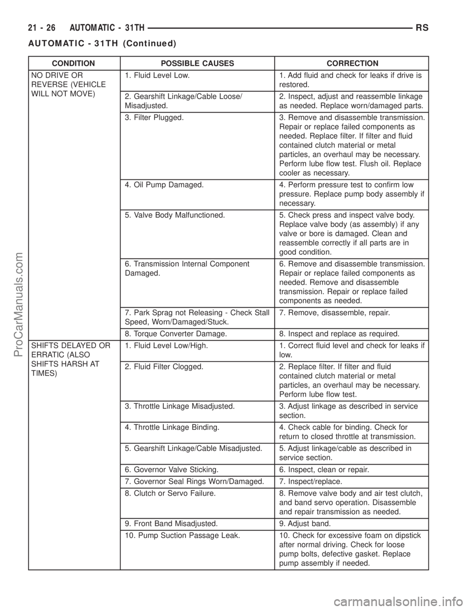
CONDITION POSSIBLE CAUSES CORRECTION
NO DRIVE OR
REVERSE (VEHICLE
WILL NOT MOVE)1. Fluid Level Low. 1. Add fluid and check for leaks if drive is
restored.
2. Gearshift Linkage/Cable Loose/
Misadjusted.2. Inspect, adjust and reassemble linkage
as needed. Replace worn/damaged parts.
3. Filter Plugged. 3. Remove and disassemble transmission.
Repair or replace failed components as
needed. Replace filter. If filter and fluid
contained clutch material or metal
particles, an overhaul may be necessary.
Perform lube flow test. Flush oil. Replace
cooler as necessary.
4. Oil Pump Damaged. 4. Perform pressure test to confirm low
pressure. Replace pump body assembly if
necessary.
5. Valve Body Malfunctioned. 5. Check press and inspect valve body.
Replace valve body (as assembly) if any
valve or bore is damaged. Clean and
reassemble correctly if all parts are in
good condition.
6. Transmission Internal Component
Damaged.6. Remove and disassemble transmission.
Repair or replace failed components as
needed. Remove and disassemble
transmission. Repair or replace failed
components as needed.
7. Park Sprag not Releasing - Check Stall
Speed, Worn/Damaged/Stuck.7. Remove, disassemble, repair.
8. Torque Converter Damage. 8. Inspect and replace as required.
SHIFTS DELAYED OR
ERRATIC (ALSO
SHIFTS HARSH AT
TIMES)1. Fluid Level Low/High. 1. Correct fluid level and check for leaks if
low.
2. Fluid Filter Clogged. 2. Replace filter. If filter and fluid
contained clutch material or metal
particles, an overhaul may be necessary.
Perform lube flow test.
3. Throttle Linkage Misadjusted. 3. Adjust linkage as described in service
section.
4. Throttle Linkage Binding. 4. Check cable for binding. Check for
return to closed throttle at transmission.
5. Gearshift Linkage/Cable Misadjusted. 5. Adjust linkage/cable as described in
service section.
6. Governor Valve Sticking. 6. Inspect, clean or repair.
7. Governor Seal Rings Worn/Damaged. 7. Inspect/replace.
8. Clutch or Servo Failure. 8. Remove valve body and air test clutch,
and band servo operation. Disassemble
and repair transmission as needed.
9. Front Band Misadjusted. 9. Adjust band.
10. Pump Suction Passage Leak. 10. Check for excessive foam on dipstick
after normal driving. Check for loose
pump bolts, defective gasket. Replace
pump assembly if needed.
21 - 26 AUTOMATIC - 31THRS
AUTOMATIC - 31TH (Continued)
ProCarManuals.com
Page 1526 of 2321
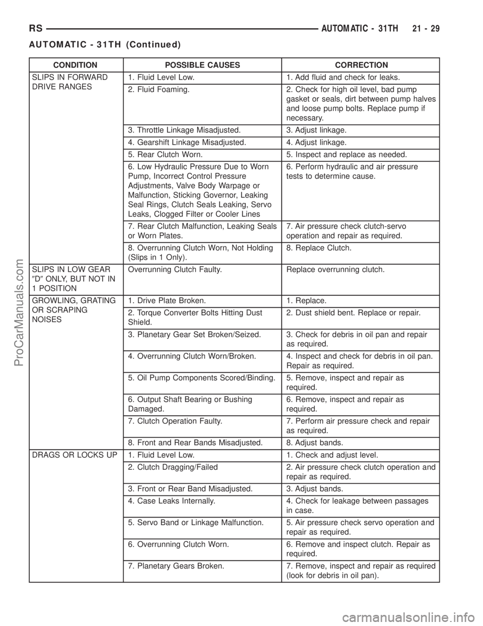
CONDITION POSSIBLE CAUSES CORRECTION
SLIPS IN FORWARD
DRIVE RANGES1. Fluid Level Low. 1. Add fluid and check for leaks.
2. Fluid Foaming. 2. Check for high oil level, bad pump
gasket or seals, dirt between pump halves
and loose pump bolts. Replace pump if
necessary.
3. Throttle Linkage Misadjusted. 3. Adjust linkage.
4. Gearshift Linkage Misadjusted. 4. Adjust linkage.
5. Rear Clutch Worn. 5. Inspect and replace as needed.
6. Low Hydraulic Pressure Due to Worn
Pump, Incorrect Control Pressure
Adjustments, Valve Body Warpage or
Malfunction, Sticking Governor, Leaking
Seal Rings, Clutch Seals Leaking, Servo
Leaks, Clogged Filter or Cooler Lines6. Perform hydraulic and air pressure
tests to determine cause.
7. Rear Clutch Malfunction, Leaking Seals
or Worn Plates.7. Air pressure check clutch-servo
operation and repair as required.
8. Overrunning Clutch Worn, Not Holding
(Slips in 1 Only).8. Replace Clutch.
SLIPS IN LOW GEAR
9D9ONLY, BUT NOT IN
1 POSITIONOverrunning Clutch Faulty. Replace overrunning clutch.
GROWLING, GRATING
OR SCRAPING
NOISES1. Drive Plate Broken. 1. Replace.
2. Torque Converter Bolts Hitting Dust
Shield.2. Dust shield bent. Replace or repair.
3. Planetary Gear Set Broken/Seized. 3. Check for debris in oil pan and repair
as required.
4. Overrunning Clutch Worn/Broken. 4. Inspect and check for debris in oil pan.
Repair as required.
5. Oil Pump Components Scored/Binding. 5. Remove, inspect and repair as
required.
6. Output Shaft Bearing or Bushing
Damaged.6. Remove, inspect and repair as
required.
7. Clutch Operation Faulty. 7. Perform air pressure check and repair
as required.
8. Front and Rear Bands Misadjusted. 8. Adjust bands.
DRAGS OR LOCKS UP 1. Fluid Level Low. 1. Check and adjust level.
2. Clutch Dragging/Failed 2. Air pressure check clutch operation and
repair as required.
3. Front or Rear Band Misadjusted. 3. Adjust bands.
4. Case Leaks Internally. 4. Check for leakage between passages
in case.
5. Servo Band or Linkage Malfunction. 5. Air pressure check servo operation and
repair as required.
6. Overrunning Clutch Worn. 6. Remove and inspect clutch. Repair as
required.
7. Planetary Gears Broken. 7. Remove, inspect and repair as required
(look for debris in oil pan).
RSAUTOMATIC - 31TH21-29
AUTOMATIC - 31TH (Continued)
ProCarManuals.com
Page 1527 of 2321
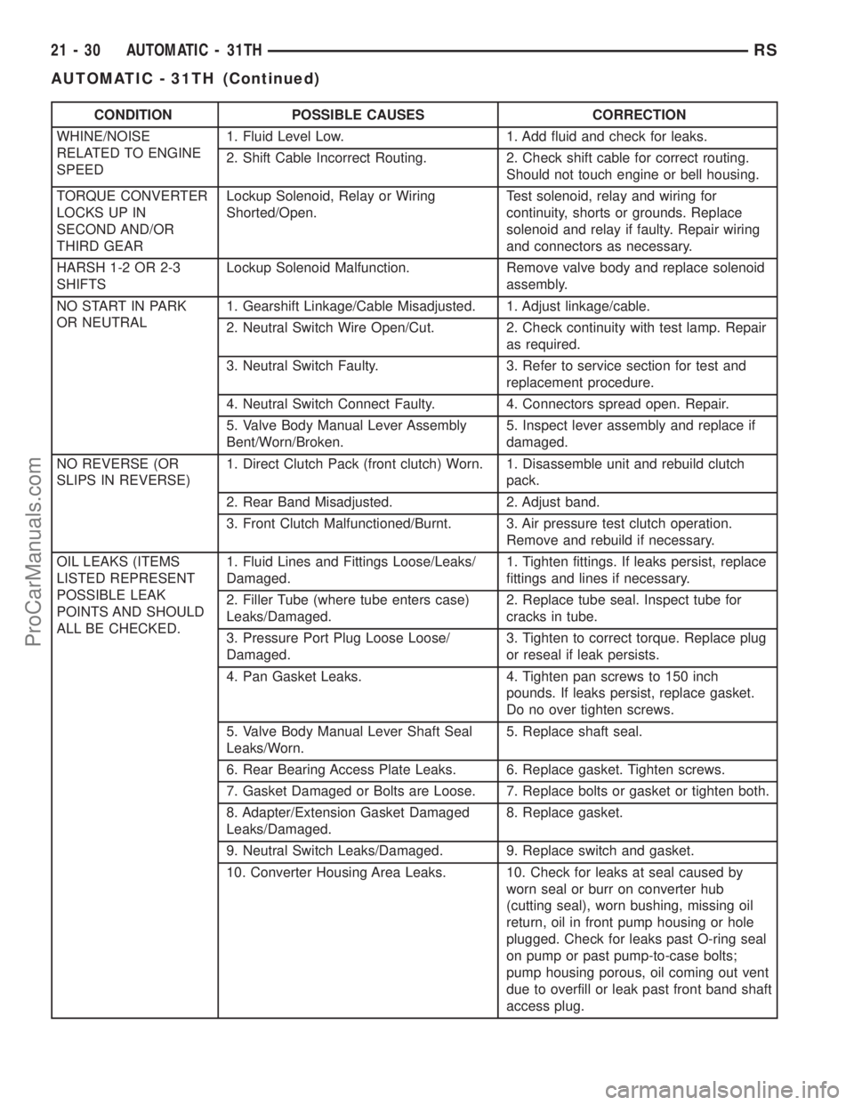
CONDITION POSSIBLE CAUSES CORRECTION
WHINE/NOISE
RELATED TO ENGINE
SPEED1. Fluid Level Low. 1. Add fluid and check for leaks.
2. Shift Cable Incorrect Routing. 2. Check shift cable for correct routing.
Should not touch engine or bell housing.
TORQUE CONVERTER
LOCKS UP IN
SECOND AND/OR
THIRD GEARLockup Solenoid, Relay or Wiring
Shorted/Open.Test solenoid, relay and wiring for
continuity, shorts or grounds. Replace
solenoid and relay if faulty. Repair wiring
and connectors as necessary.
HARSH 1-2 OR 2-3
SHIFTSLockup Solenoid Malfunction. Remove valve body and replace solenoid
assembly.
NO START IN PARK
OR NEUTRAL1. Gearshift Linkage/Cable Misadjusted. 1. Adjust linkage/cable.
2. Neutral Switch Wire Open/Cut. 2. Check continuity with test lamp. Repair
as required.
3. Neutral Switch Faulty. 3. Refer to service section for test and
replacement procedure.
4. Neutral Switch Connect Faulty. 4. Connectors spread open. Repair.
5. Valve Body Manual Lever Assembly
Bent/Worn/Broken.5. Inspect lever assembly and replace if
damaged.
NO REVERSE (OR
SLIPS IN REVERSE)1. Direct Clutch Pack (front clutch) Worn. 1. Disassemble unit and rebuild clutch
pack.
2. Rear Band Misadjusted. 2. Adjust band.
3. Front Clutch Malfunctioned/Burnt. 3. Air pressure test clutch operation.
Remove and rebuild if necessary.
OIL LEAKS (ITEMS
LISTED REPRESENT
POSSIBLE LEAK
POINTS AND SHOULD
ALL BE CHECKED.1. Fluid Lines and Fittings Loose/Leaks/
Damaged.1. Tighten fittings. If leaks persist, replace
fittings and lines if necessary.
2. Filler Tube (where tube enters case)
Leaks/Damaged.2. Replace tube seal. Inspect tube for
cracks in tube.
3. Pressure Port Plug Loose Loose/
Damaged.3. Tighten to correct torque. Replace plug
or reseal if leak persists.
4. Pan Gasket Leaks. 4. Tighten pan screws to 150 inch
pounds. If leaks persist, replace gasket.
Do no over tighten screws.
5. Valve Body Manual Lever Shaft Seal
Leaks/Worn.5. Replace shaft seal.
6. Rear Bearing Access Plate Leaks. 6. Replace gasket. Tighten screws.
7. Gasket Damaged or Bolts are Loose. 7. Replace bolts or gasket or tighten both.
8. Adapter/Extension Gasket Damaged
Leaks/Damaged.8. Replace gasket.
9. Neutral Switch Leaks/Damaged. 9. Replace switch and gasket.
10. Converter Housing Area Leaks. 10. Check for leaks at seal caused by
worn seal or burr on converter hub
(cutting seal), worn bushing, missing oil
return, oil in front pump housing or hole
plugged. Check for leaks past O-ring seal
on pump or past pump-to-case bolts;
pump housing porous, oil coming out vent
due to overfill or leak past front band shaft
access plug.
21 - 30 AUTOMATIC - 31THRS
AUTOMATIC - 31TH (Continued)
ProCarManuals.com
Page 1578 of 2321
OPERATION
To apply the clutch, pressure is applied between
the clutch retainer and piston. The fluid pressure is
provided by the oil pump, transferred through the
control valves and passageways, and enters the
clutch through the hub of the reaction shaft support.
With pressure applied between the clutch retainer
and piston, the piston moves away from the clutch
retainer and compresses the clutch pack. This action
applies the clutch pack, allowing torque to flow
through the input shaft into the driving discs, and
into the clutch plates and pressure plate that are
lugged to the clutch retainer. The waved snap-ring is
used to cushion the application of the clutch pack. In
some transmissions, the snap-ring is selective and
used to adjust clutch pack clearance.
When pressure is released from the piston, the
spring returns the piston to its fully released position
and disengages the clutch. The release spring also
helps to cushion the application of the clutch assem-
bly. When the clutch is in the process of being
released by the release spring, fluid flows through a
vent and one-way ball-check-valve located in the
clutch retainer. The check-valve is needed to elimi-
nate the possibility of plate drag caused by centrifu-
gal force acting on the residual fluid trapped in the
clutch piston retainer.
DISASSEMBLY
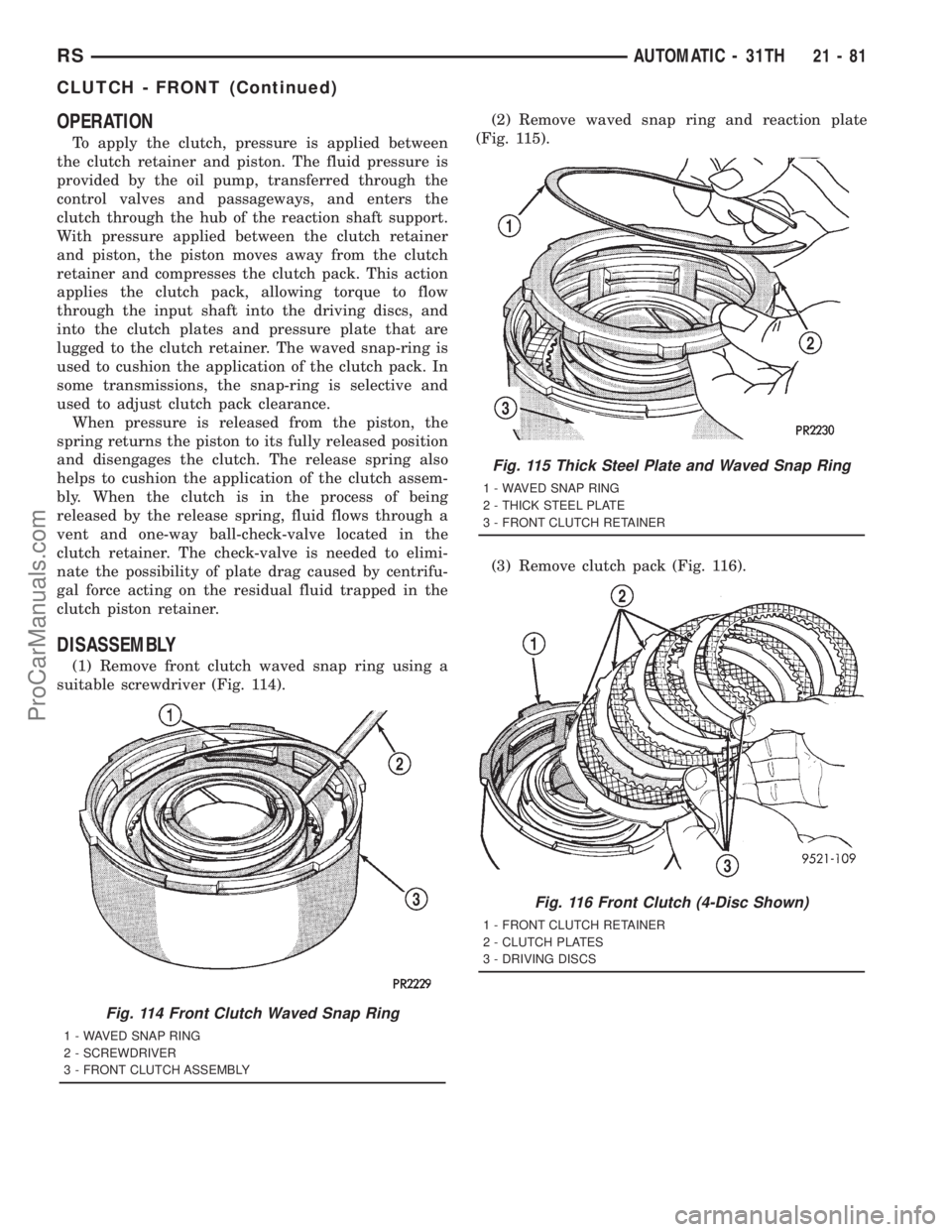
(1) Remove front clutch waved snap ring using a
suitable screwdriver (Fig. 114).(2) Remove waved snap ring and reaction plate
(Fig. 115).
(3) Remove clutch pack (Fig. 116).
Fig. 114 Front Clutch Waved Snap Ring
1 - WAVED SNAP RING
2 - SCREWDRIVER
3 - FRONT CLUTCH ASSEMBLY
Fig. 115 Thick Steel Plate and Waved Snap Ring
1 - WAVED SNAP RING
2 - THICK STEEL PLATE
3 - FRONT CLUTCH RETAINER
Fig. 116 Front Clutch (4-Disc Shown)
1 - FRONT CLUTCH RETAINER
2 - CLUTCH PLATES
3 - DRIVING DISCS
RSAUTOMATIC - 31TH21-81
CLUTCH - FRONT (Continued)
ProCarManuals.com