2001 DODGE TOWN AND COUNTRY wheel bolts
[x] Cancel search: wheel boltsPage 1346 of 2321
INSPECTION
Clean each lifter assembly in cleaning solvent to
remove all varnish and sludge deposits. Inspect for
indications of scuffing on the side and base of each
lifter body.
INSTALLATION
(1) Install rocker arm and lifter assemblies in
lifter bores.
(2) Install cylinder head cover/intake manifold
(Fig. 33) (Refer to 9 - ENGINE/CYLINDER HEAD/
CYLINDER HEAD COVER(S) - INSTALLATION).
(3) Install timing belt inner cover (Refer to 9 -
ENGINE/VALVE TIMING/TIMING BELT / CHAIN
COVER(S) - INSTALLATION).
(4) Install timing belt (Refer to 9 - ENGINE/
VALVE TIMING/TIMING BELT/CHAIN AND
SPROCKETS - INSTALLATION) .
(5) Install timing belt outer cover (Refer to 9 -
ENGINE/VALVE TIMING/TIMING BELT / CHAIN
COVER(S) - INSTALLATION).
(6) Install right engine mount (Refer to 9 -
ENGINE/ENGINE MOUNTING/RIGHT MOUNT -
INSTALLATION).
(7) Install engine cover (Refer to 9 - ENGINE -
INSTALLATION).
(8) Install front wiper unit (Refer to 8 - ELECTRI-
CAL/WIPERS/WASHERS/WIPER MODULE -
INSTALLATION).
(9) Connect negative battery cable.
ENGINE BLOCK
DESCRIPTION
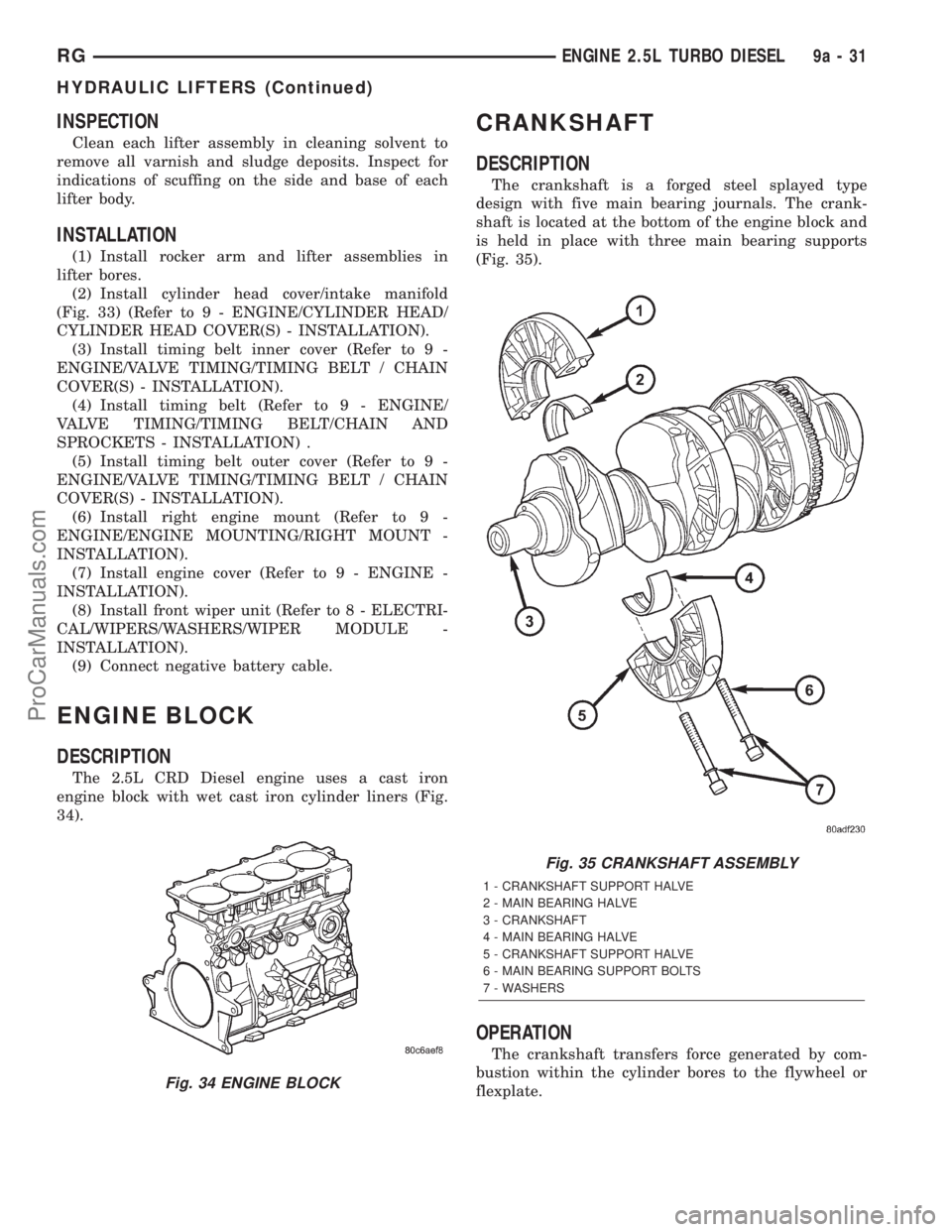
The 2.5L CRD Diesel engine uses a cast iron
engine block with wet cast iron cylinder liners (Fig.
34).
CRANKSHAFT
DESCRIPTION
The crankshaft is a forged steel splayed type
design with five main bearing journals. The crank-
shaft is located at the bottom of the engine block and
is held in place with three main bearing supports
(Fig. 35).
OPERATION
The crankshaft transfers force generated by com-
bustion within the cylinder bores to the flywheel or
flexplate.
Fig. 34 ENGINE BLOCK
Fig. 35 CRANKSHAFT ASSEMBLY
1 - CRANKSHAFT SUPPORT HALVE
2 - MAIN BEARING HALVE
3 - CRANKSHAFT
4 - MAIN BEARING HALVE
5 - CRANKSHAFT SUPPORT HALVE
6 - MAIN BEARING SUPPORT BOLTS
7 - WASHERS
RGENGINE 2.5L TURBO DIESEL9a-31
HYDRAULIC LIFTERS (Continued)
ProCarManuals.com
Page 1347 of 2321
STANDARD PROCEDURE - CHECKING
CRANKSHAFT END PLAY
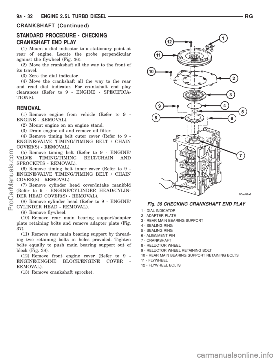
(1) Mount a dial indicator to a stationary point at
rear of engine. Locate the probe perpendicular
against the flywheel (Fig. 36).
(2) Move the crankshaft all the way to the front of
its travel.
(3) Zero the dial indicator.
(4) Move the crankshaft all the way to the rear
and read dial indicator. For crankshaft end play
clearances (Refer to 9 - ENGINE - SPECIFICA-
TIONS).
REMOVAL
(1) Remove engine from vehicle (Refer to 9 -
ENGINE - REMOVAL).
(2) Mount engine on an engine stand.
(3) Drain engine oil and remove oil filter.
(4) Remove timing belt outer cover (Refer to 9 -
ENGINE/VALVE TIMING/TIMING BELT / CHAIN
COVER(S) - REMOVAL).
(5) Remove timing belt (Refer to 9 - ENGINE/
VALVE TIMING/TIMING BELT/CHAIN AND
SPROCKETS - REMOVAL).
(6) Remove timing belt inner cover (Refer to 9 -
ENGINE/VALVE TIMING/TIMING BELT / CHAIN
COVER(S) - REMOVAL).
(7) Remove cylinder head cover/intake manifold
(Refer to 9 - ENGINE/CYLINDER HEAD/CYLIN-
DER HEAD COVER(S) - REMOVAL).
(8) Remove cylinder head (Refer to 9 - ENGINE/
CYLINDER HEAD - REMOVAL).
(9) Remove flywheel.
(10) Remove rear main bearing support/adapter
plate retaining bolts and remove adapter plate (Fig.
37).
(11) Remove rear main bearing support by thread-
ing two retaining bolts in holes provided. Tighten
bolts equally to push main bearing support out of
block (Fig. 38).
(12) Remove front engine cover (Refer to 9 -
ENGINE/ENGINE BLOCK/ENGINE COVER -
REMOVAL).
(13) Remove crankshaft sprocket.
Fig. 36 CHECKING CRANKSHAFT END PLAY
1 - DIAL INDICATOR
2 - ADAPTER PLATE
3 - REAR MAIN BEARING SUPPORT
4 - SEALING RING
5 - SEALING RING
6 - ALIGNMENT PIN
7 - CRANKSHAFT
8 - RELUCTOR WHEEL
9 - RELUCTOR WHEEL RETAINING BOLT
10 - REAR MAIN BEARING SUPPORT RETAINING BOLTS
11 - FLYWHEEL
12 - FLYWHEEL BOLTS
9a - 32 ENGINE 2.5L TURBO DIESELRG
CRANKSHAFT (Continued)
ProCarManuals.com
Page 1349 of 2321
(5) Install front engine cover (Refer to 9 -
ENGINE/ENGINE BLOCK/ENGINE COVER -
INSTALLATION).
(6) Install rear main bearing support in engine
block.Be sure to align oil hole in rear main
bearing support with hole in block.
(7) Install adapter plate and retaining bolts (Fig.
37). Torque bolts to 27.5N´m.
(8) Install flywheel.
(9) Install piston and connecting rod assemblies
(Refer to 9 - ENGINE/ENGINE BLOCK/PISTON &
CONNECTING ROD - INSTALLATION).
(10) Install oil jets (Refer to 9 - ENGINE/LUBRI-
CATION/OIL JET - INSTALLATION).
(11) Install balance shaft assembly (Refer to 9 -
ENGINE/VALVE TIMING/BALANCE SHAFT -
INSTALLATION).
(12) Install oil pump pickup tube (Refer to 9 -
ENGINE/LUBRICATION/OIL PUMP - INSTALLA-
TION).
(13) Install oil pan (Refer to 9 - ENGINE/LUBRI-
CATION/OIL PAN - INSTALLATION).
(14) Install cylinder head (Refer to 9 - ENGINE/
CYLINDER HEAD - INSTALLATION).
(15) Install cylinder head cover/intake manifold
(Refer to 9 - ENGINE/CYLINDER HEAD/CYLIN-
DER HEAD COVER(S) - INSTALLATION).
(16) Install timing belt inner cover (Refer to 9 -
ENGINE/VALVE TIMING/TIMING BELT / CHAIN
COVER(S) - INSTALLATION).
(17) Install timing belt (Refer to 9 - ENGINE/
VALVE TIMING/TIMING BELT/CHAIN AND
SPROCKETS - INSTALLATION) .(18) Install timing belt outer cover (Refer to 9 -
ENGINE/VALVE TIMING/TIMING BELT / CHAIN
COVER(S) - INSTALLATION).
(19) Install engine in vehicle.
(20) Fill engine oil with proper oil to correct level.
CYLINDER LINERS
DESCRIPTION
The cylinder wall liner used on this engine is of
the wet design. O-rings are used to seal the liner to
the engine block.
REMOVAL
(1) Remove engine from vehicle.
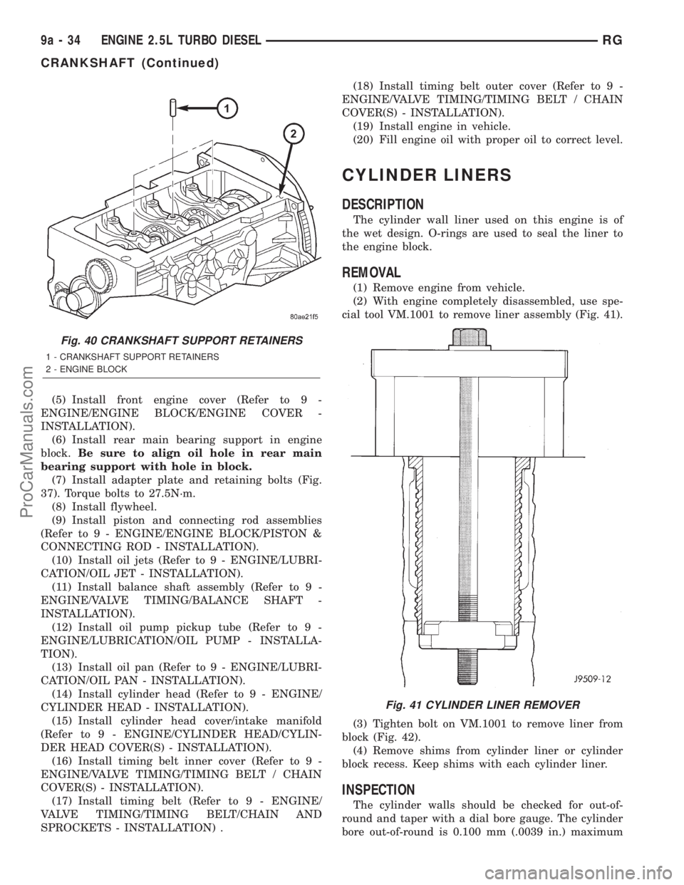
(2) With engine completely disassembled, use spe-
cial tool VM.1001 to remove liner assembly (Fig. 41).
(3) Tighten bolt on VM.1001 to remove liner from
block (Fig. 42).
(4) Remove shims from cylinder liner or cylinder
block recess. Keep shims with each cylinder liner.
INSPECTION
The cylinder walls should be checked for out-of-
round and taper with a dial bore gauge. The cylinder
bore out-of-round is 0.100 mm (.0039 in.) maximum
Fig. 40 CRANKSHAFT SUPPORT RETAINERS
1 - CRANKSHAFT SUPPORT RETAINERS
2 - ENGINE BLOCK
Fig. 41 CYLINDER LINER REMOVER
9a - 34 ENGINE 2.5L TURBO DIESELRG
CRANKSHAFT (Continued)
ProCarManuals.com
Page 1361 of 2321
INSTALLATION
CRANKSHAFT MAIN BEARINGS
(1) Install bearing halves in crankshaft supports.
(2) Lubricate crankshaft and main bearings with
clean engine oil.
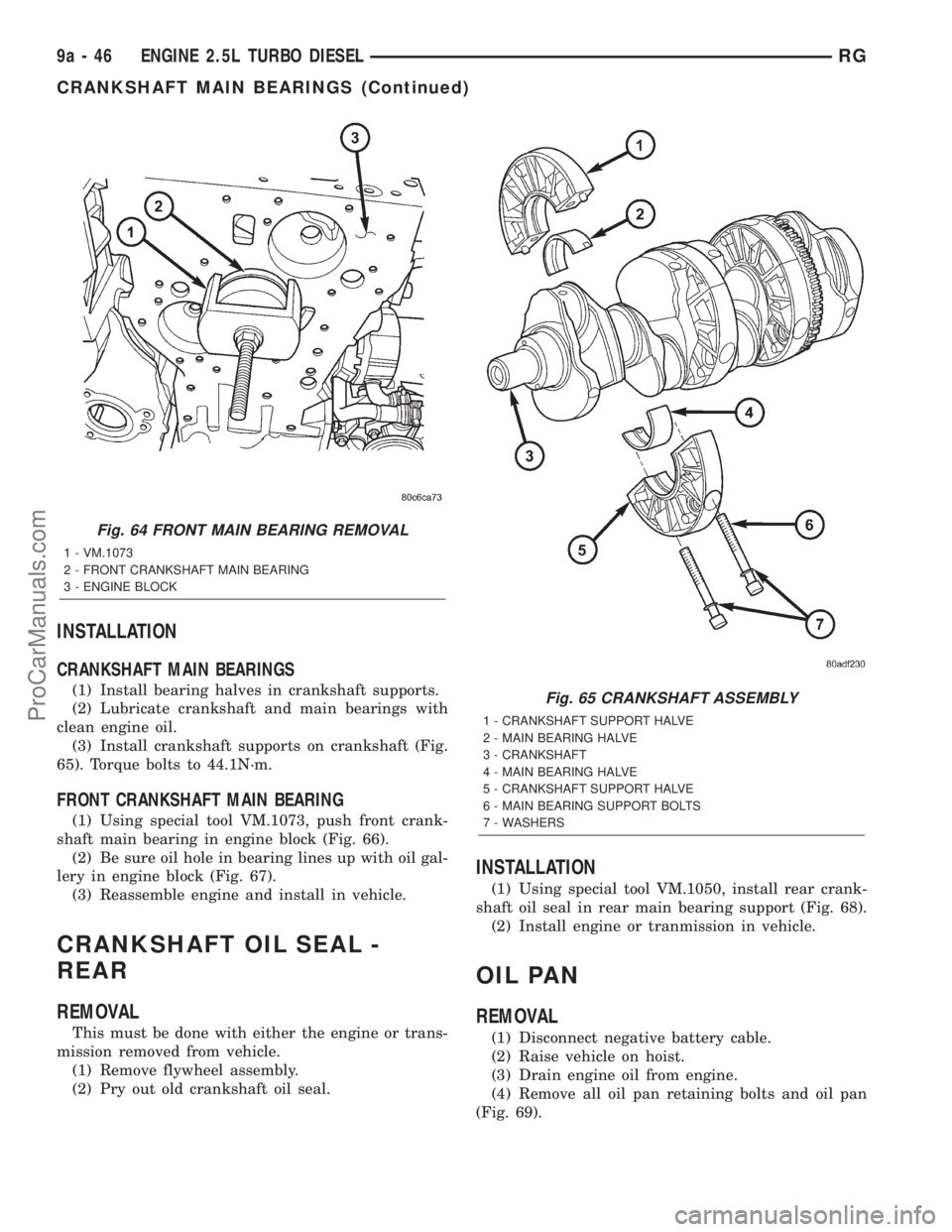
(3) Install crankshaft supports on crankshaft (Fig.
65). Torque bolts to 44.1N´m.
FRONT CRANKSHAFT MAIN BEARING
(1) Using special tool VM.1073, push front crank-
shaft main bearing in engine block (Fig. 66).
(2) Be sure oil hole in bearing lines up with oil gal-
lery in engine block (Fig. 67).
(3) Reassemble engine and install in vehicle.
CRANKSHAFT OIL SEAL -
REAR
REMOVAL
This must be done with either the engine or trans-
mission removed from vehicle.
(1) Remove flywheel assembly.
(2) Pry out old crankshaft oil seal.
INSTALLATION
(1) Using special tool VM.1050, install rear crank-
shaft oil seal in rear main bearing support (Fig. 68).
(2) Install engine or tranmission in vehicle.
OIL PAN
REMOVAL
(1) Disconnect negative battery cable.
(2) Raise vehicle on hoist.
(3) Drain engine oil from engine.
(4) Remove all oil pan retaining bolts and oil pan
(Fig. 69).
Fig. 64 FRONT MAIN BEARING REMOVAL
1 - VM.1073
2 - FRONT CRANKSHAFT MAIN BEARING
3 - ENGINE BLOCK
Fig. 65 CRANKSHAFT ASSEMBLY
1 - CRANKSHAFT SUPPORT HALVE
2 - MAIN BEARING HALVE
3 - CRANKSHAFT
4 - MAIN BEARING HALVE
5 - CRANKSHAFT SUPPORT HALVE
6 - MAIN BEARING SUPPORT BOLTS
7 - WASHERS
9a - 46 ENGINE 2.5L TURBO DIESELRG
CRANKSHAFT MAIN BEARINGS (Continued)
ProCarManuals.com
Page 1372 of 2321
INSTALLATION
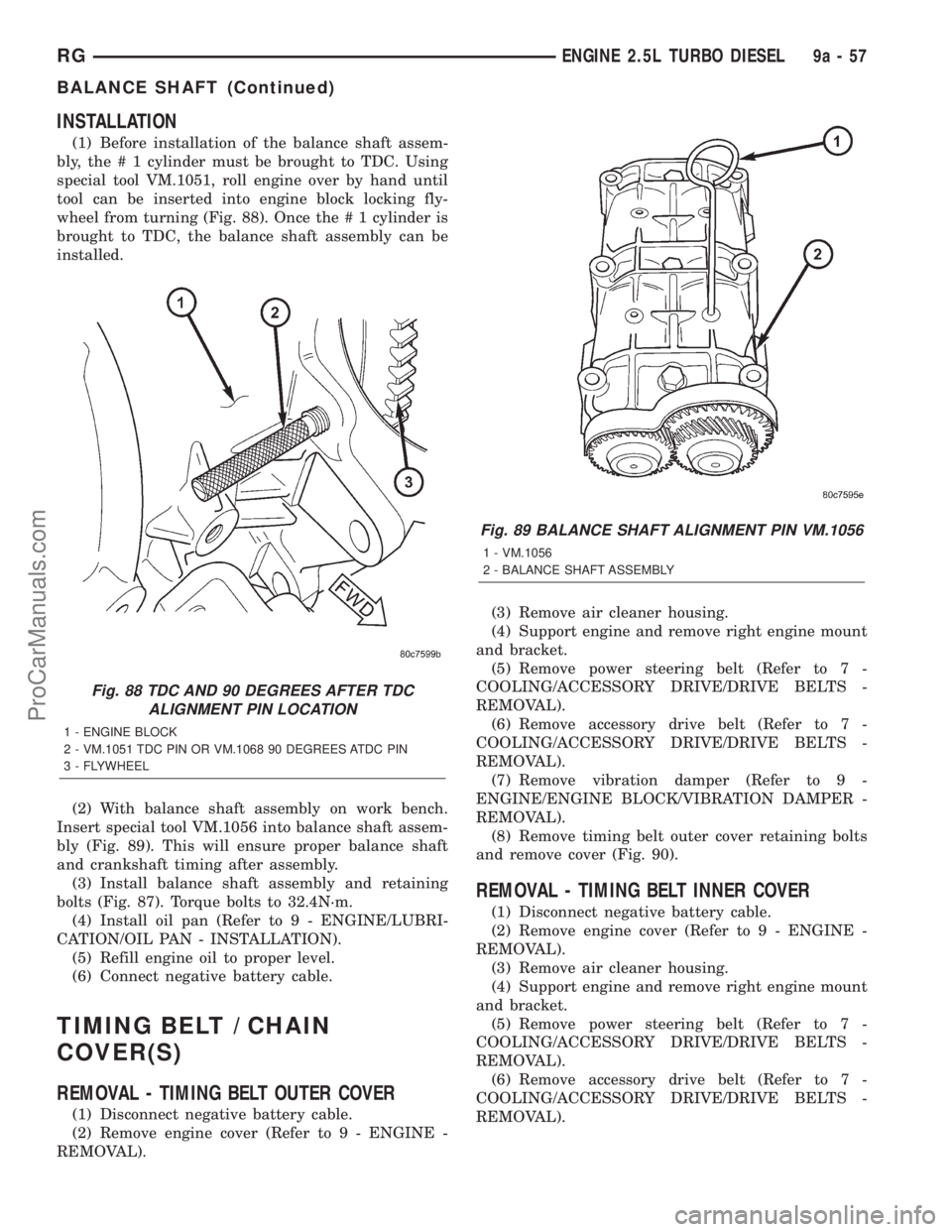
(1) Before installation of the balance shaft assem-
bly, the # 1 cylinder must be brought to TDC. Using
special tool VM.1051, roll engine over by hand until
tool can be inserted into engine block locking fly-
wheel from turning (Fig. 88). Once the # 1 cylinder is
brought to TDC, the balance shaft assembly can be
installed.
(2) With balance shaft assembly on work bench.
Insert special tool VM.1056 into balance shaft assem-
bly (Fig. 89). This will ensure proper balance shaft
and crankshaft timing after assembly.
(3) Install balance shaft assembly and retaining
bolts (Fig. 87). Torque bolts to 32.4N´m.
(4) Install oil pan (Refer to 9 - ENGINE/LUBRI-
CATION/OIL PAN - INSTALLATION).
(5) Refill engine oil to proper level.
(6) Connect negative battery cable.
TIMING BELT / CHAIN
COVER(S)
REMOVAL - TIMING BELT OUTER COVER
(1) Disconnect negative battery cable.
(2) Remove engine cover (Refer to 9 - ENGINE -
REMOVAL).(3) Remove air cleaner housing.
(4) Support engine and remove right engine mount
and bracket.
(5) Remove power steering belt (Refer to 7 -
COOLING/ACCESSORY DRIVE/DRIVE BELTS -
REMOVAL).
(6) Remove accessory drive belt (Refer to 7 -
COOLING/ACCESSORY DRIVE/DRIVE BELTS -
REMOVAL).
(7) Remove vibration damper (Refer to 9 -
ENGINE/ENGINE BLOCK/VIBRATION DAMPER -
REMOVAL).
(8) Remove timing belt outer cover retaining bolts
and remove cover (Fig. 90).
REMOVAL - TIMING BELT INNER COVER
(1) Disconnect negative battery cable.
(2) Remove engine cover (Refer to 9 - ENGINE -
REMOVAL).
(3) Remove air cleaner housing.
(4) Support engine and remove right engine mount
and bracket.
(5) Remove power steering belt (Refer to 7 -
COOLING/ACCESSORY DRIVE/DRIVE BELTS -
REMOVAL).
(6) Remove accessory drive belt (Refer to 7 -
COOLING/ACCESSORY DRIVE/DRIVE BELTS -
REMOVAL).
Fig. 88 TDC AND 90 DEGREES AFTER TDC
ALIGNMENT PIN LOCATION
1 - ENGINE BLOCK
2 - VM.1051 TDC PIN OR VM.1068 90 DEGREES ATDC PIN
3 - FLYWHEEL
Fig. 89 BALANCE SHAFT ALIGNMENT PIN VM.1056
1 - VM.1056
2 - BALANCE SHAFT ASSEMBLY
RGENGINE 2.5L TURBO DIESEL9a-57
BALANCE SHAFT (Continued)
ProCarManuals.com
Page 1395 of 2321
FRONT FASCIA
REMOVAL
(1) Release hood latch and open hood.
(2) Remove the headlamp assemblies. Refer to
group 8 exterior lighting.
(3) Remove two bolts attaching the upper grill sup-
port to the headlamp mounting panel at each side of
the grille.
(4) Hoist vehicle and support with safety stands.
(5)
Remove front wheels. Refer to Group 22, Wheels
and Tires, for proper procedures and sequence.
(6) Remove front wheelhouse splash shields fasten-
ers as necessary to gain access to bolts holding front
fascia to fender. Refer to Group 23, Body, for proper
procedures.
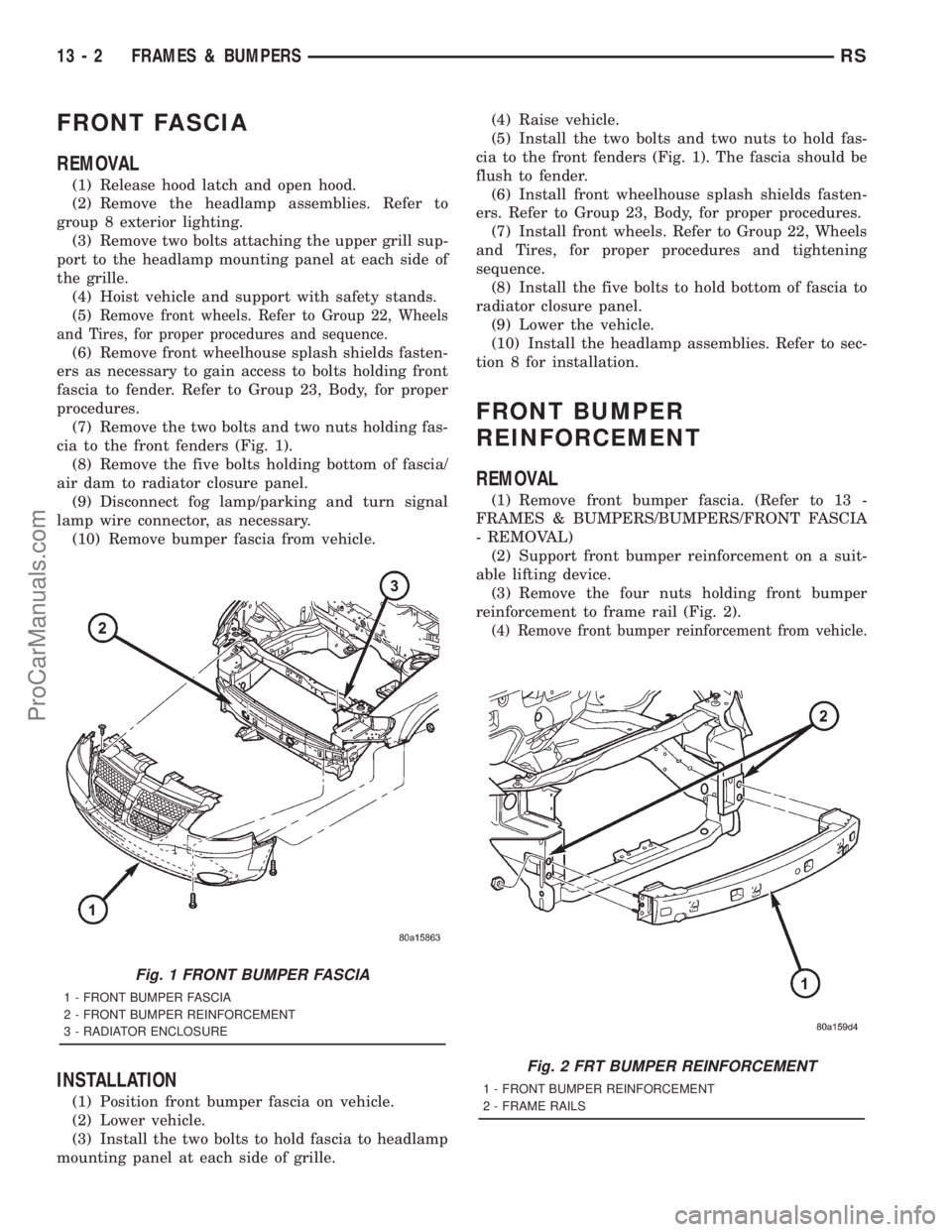
(7) Remove the two bolts and two nuts holding fas-
cia to the front fenders (Fig. 1).
(8) Remove the five bolts holding bottom of fascia/
air dam to radiator closure panel.
(9) Disconnect fog lamp/parking and turn signal
lamp wire connector, as necessary.
(10) Remove bumper fascia from vehicle.
INSTALLATION
(1) Position front bumper fascia on vehicle.
(2) Lower vehicle.
(3) Install the two bolts to hold fascia to headlamp
mounting panel at each side of grille.(4) Raise vehicle.
(5) Install the two bolts and two nuts to hold fas-
cia to the front fenders (Fig. 1). The fascia should be
flush to fender.
(6) Install front wheelhouse splash shields fasten-
ers. Refer to Group 23, Body, for proper procedures.
(7) Install front wheels. Refer to Group 22, Wheels
and Tires, for proper procedures and tightening
sequence.
(8) Install the five bolts to hold bottom of fascia to
radiator closure panel.
(9) Lower the vehicle.
(10) Install the headlamp assemblies. Refer to sec-
tion 8 for installation.
FRONT BUMPER
REINFORCEMENT
REMOVAL
(1) Remove front bumper fascia. (Refer to 13 -
FRAMES & BUMPERS/BUMPERS/FRONT FASCIA
- REMOVAL)
(2) Support front bumper reinforcement on a suit-
able lifting device.
(3) Remove the four nuts holding front bumper
reinforcement to frame rail (Fig. 2).
(4) Remove front bumper reinforcement from vehicle.
Fig. 1 FRONT BUMPER FASCIA
1 - FRONT BUMPER FASCIA
2 - FRONT BUMPER REINFORCEMENT
3 - RADIATOR ENCLOSURE
Fig. 2 FRT BUMPER REINFORCEMENT
1 - FRONT BUMPER REINFORCEMENT
2 - FRAME RAILS
13 - 2 FRAMES & BUMPERSRS
ProCarManuals.com
Page 1403 of 2321
²Needle Nose Pliers ± For Removal Of Thread
Insert Driving Tang
REMOVAL
The front cradle crossmember must be installed in
the design location to achieve proper front end sus-
pension alignment. If the cradle crossmember is
removed without applying reference marks on the
frame rails, align the cradle crossmember according
to the dimensions provided in this group.
NOTE: If the caged nuts in the frame rails become
damaged and cannot be reused, a replacement nut
can be obtained through MoparT.
REMOVAL
(1) Disconnect battery negative cable.
(2) Remove steering column lower cover from
instrument panel. Refer to Group 8E, Instrument
Panel and Systems.
(3) Remove knee blocker reinforcement. Refer to
Group 8E, Instrument Panel and Systems.
(4) Position steering so front wheels are straight
ahead.
CAUTION: Do not rotate steering wheel after disen-
gaging lower coupling from steering gear, damage
to air bag clock spring can result.
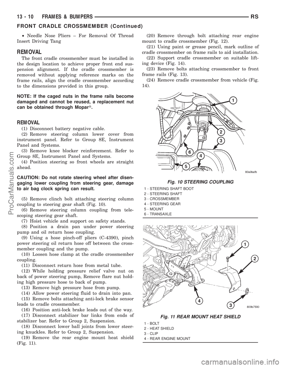
(5) Remove clinch bolt attaching steering column
coupling to steering gear shaft (Fig. 10).
(6) Remove steering column coupling from tele-
scoping steering gear shaft.
(7) Hoist vehicle and support on safety stands.
(8) Position a drain pan under power steering
pump and oil return hose coupling.
(9) Using a hose pinch-off pliers (C-4390), pinch
power steering oil return hose off between the cross-
member coupling and the pump.
(10) Loosen hose clamp at the cradle crossmember
coupling.
(11) Disconnect return hose from metal tube.
(12) While holding pressure relief valve nut on
back of power steering pump, Remove flare nut hold-
ing high pressure hose to back of pump.
(13) Remove high pressure hose from pump.
(14) Allow power steering fluid to drain into pan.
(15) Remove bolts attaching anti-lock brake sensor
leads to cradle crossmember.
(16) Position anti-lock brake leads out of the way.
(17) Disconnect stabilizer bar links from ends of
stabilizer bar. Refer to Group 2, Suspension.
(18) Disconnect lower ball joints from lower steer-
ing knuckles. Refer to Group 2, Suspension.
(19) Remove the rear engine mount heat shield
(Fig. 11).(20) Remove through bolt attaching rear engine
mount to cradle crossmember (Fig. 12).
(21) Using paint or grease pencil, mark outline of
cradle crossmember on frame rails to aid installation.
(22) Support cradle crossmember on suitable lift-
ing device (Fig. 14).
(23) Remove bolts attaching crossmember to front
frame rails (Fig. 13).
(24) Remove cradle crossmember from vehicle (Fig.
14).
Fig. 10 STEERING COUPLING
1 - STEERING SHAFT BOOT
2 - STEERING SHAFT
3 - CROSSMEMBER
4 - STEERING GEAR
5 - MOUNT
6 - TRANSAXLE
Fig. 11 REAR MOUNT HEAT SHIELD
1 - BOLT
2 - HEAT SHIELD
3 - CLIP
4 - REAR ENGINE MOUNT
13 - 10 FRAMES & BUMPERSRS
FRONT CRADLE CROSSMEMBER (Continued)
ProCarManuals.com
Page 1404 of 2321
INSTALLATION
NOTE: If cradle crossmember requires replacement.
Refer to Group 2, Suspension, to transfer suspen-
sion components and Group 19, Steering, to trans-
fer steering components.
(1) Support crossmember on suitable lifting device
(Fig. 14).
(2) Position crossmember to vehicle.(3) Loosely install bolts attaching cradle cross-
member to front frame rails.
(4) Align crossmember to previously made marks
on frame rails.
(5) Tighten bolts attaching cradle crossmember to
frame rails.
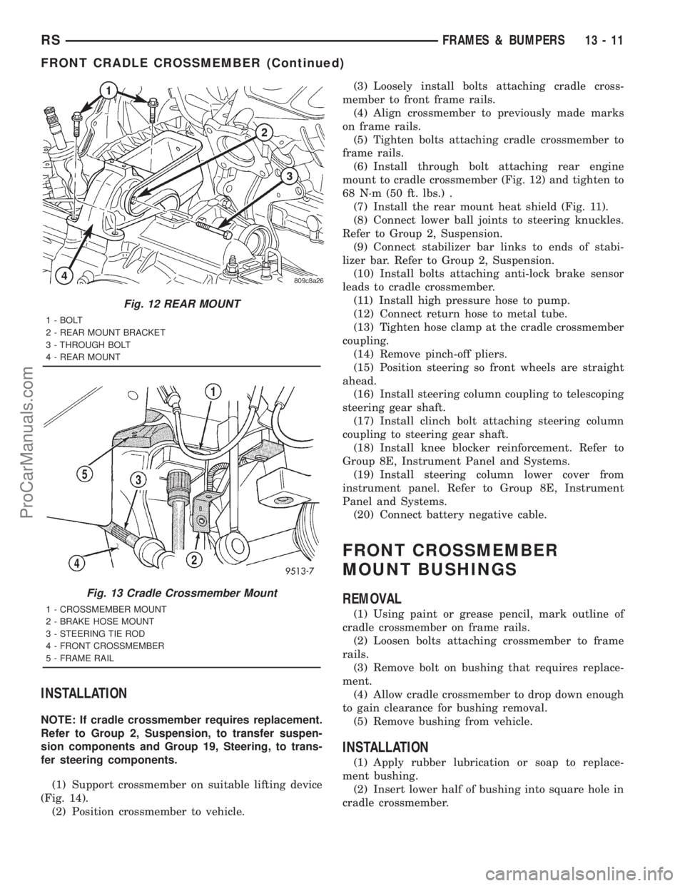
(6) Install through bolt attaching rear engine
mount to cradle crossmember (Fig. 12) and tighten to
68 N´m (50 ft. lbs.) .
(7) Install the rear mount heat shield (Fig. 11).
(8) Connect lower ball joints to steering knuckles.
Refer to Group 2, Suspension.
(9) Connect stabilizer bar links to ends of stabi-
lizer bar. Refer to Group 2, Suspension.
(10) Install bolts attaching anti-lock brake sensor
leads to cradle crossmember.
(11) Install high pressure hose to pump.
(12) Connect return hose to metal tube.
(13) Tighten hose clamp at the cradle crossmember
coupling.
(14) Remove pinch-off pliers.
(15) Position steering so front wheels are straight
ahead.
(16) Install steering column coupling to telescoping
steering gear shaft.
(17) Install clinch bolt attaching steering column
coupling to steering gear shaft.
(18) Install knee blocker reinforcement. Refer to
Group 8E, Instrument Panel and Systems.
(19) Install steering column lower cover from
instrument panel. Refer to Group 8E, Instrument
Panel and Systems.
(20) Connect battery negative cable.
FRONT CROSSMEMBER
MOUNT BUSHINGS
REMOVAL
(1) Using paint or grease pencil, mark outline of
cradle crossmember on frame rails.
(2) Loosen bolts attaching crossmember to frame
rails.
(3) Remove bolt on bushing that requires replace-
ment.
(4) Allow cradle crossmember to drop down enough
to gain clearance for bushing removal.
(5) Remove bushing from vehicle.
INSTALLATION
(1) Apply rubber lubrication or soap to replace-
ment bushing.
(2) Insert lower half of bushing into square hole in
cradle crossmember.
Fig. 12 REAR MOUNT
1 - BOLT
2 - REAR MOUNT BRACKET
3 - THROUGH BOLT
4 - REAR MOUNT
Fig. 13 Cradle Crossmember Mount
1 - CROSSMEMBER MOUNT
2 - BRAKE HOSE MOUNT
3 - STEERING TIE ROD
4 - FRONT CROSSMEMBER
5 - FRAME RAIL
RSFRAMES & BUMPERS13-11
FRONT CRADLE CROSSMEMBER (Continued)
ProCarManuals.com