2001 DODGE TOWN AND COUNTRY wheel bolts
[x] Cancel search: wheel boltsPage 248 of 2321
CAUTION: Before removing the brake tubes from
the HCU, the HCU must be thoroughly cleaned. This
must be done to prevent dirt particles from falling
into the ports of HCU or entering the brake tubes.
(6) Thoroughly clean all surfaces of the HCU, and
all brake tube nuts located on the HCU. Use only a
solvent such as Mopar Brake Parts Cleaner or an
equivalent to clean the HCU.
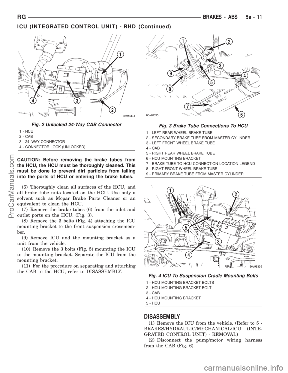
(7) Remove the brake tubes (6) from the inlet and
outlet ports on the HCU. (Fig. 3).
(8) Remove the 3 bolts (Fig. 4) attaching the ICU
mounting bracket to the front suspension crossmem-
ber.
(9) Remove ICU and the mounting bracket as a
unit from the vehicle.
(10) Remove the 3 bolts (Fig. 5) mounting the ICU
to the mounting bracket. Separate the ICU from the
mounting bracket.
(11) For the procedure on separating and attaching
the CAB to the HCU, refer to DISASSEMBLY.
DISASSEMBLY
(1) Remove the ICU from the vehicle. (Refer to 5 -
BRAKES/HYDRAULIC/MECHANICAL/ICU (INTE-
GRATED CONTROL UNIT) - REMOVAL)
(2) Disconnect the pump/motor wiring harness
from the CAB (Fig. 6).
Fig. 2 Unlocked 24-Way CAB Connector
1 - HCU
2 - CAB
3 - 24±WAY CONNECTOR
4 - CONNECTOR LOCK (UNLOCKED)
Fig. 3 Brake Tube Connections To HCU
1 - LEFT REAR WHEEL BRAKE TUBE
2 - SECONDARY BRAKE TUBE FROM MASTER CYLINDER
3 - LEFT FRONT WHEEL BRAKE TUBE
4 - CAB
5 - RIGHT REAR WHEEL BRAKE TUBE
6 - HCU MOUNTING BRACKET
7 - BRAKE TUBE TO HCU CONNECTION LOCATION LEGEND
8 - RIGHT FRONT WHEEL BRAKE TUBE
9 - PRIMARY BRAKE TUBE FROM MASTER CYLINDER
Fig. 4 ICU To Suspension Cradle Mounting Bolts
1 - HCU MOUNTING BRACKET BOLTS
2 - HCU MOUNTING BRACKET BOLT
3 - CAB
4 - HCU MOUNTING BRACKET
5 - HCU
RGBRAKES - ABS5a-11
ICU (INTEGRATED CONTROL UNIT) - RHD (Continued)
ProCarManuals.com
Page 258 of 2321
DIAGNOSIS AND TESTING - DRIVE PLATE
MISALIGNMENT
Common causes of misalignment are:
²Heat warping
²Mounting drive plate on a dirty crankshaft
flange
²Incorrect bolt tightening
²Improper seating on the crankshaft shoulder
²Loose crankshaft bolts
Clean the crankshaft flange before mounting the
drive plate. Dirt and grease on the flange surface
may misalign the flywheel, causing excessive runout.
Use new bolts when mounting drive plate to crank-
shaft. Tighten drive plate bolts to specified torque
only. Over-tightening can distort the drive plate hub
causing excessive runout.
DIAGNOSIS AND TESTING - CLUTCH COVER
AND DISC RUNOUT
Check condition of the clutch cover before installa-
tion. A warped cover or diaphragm spring will cause
grab and/or incomplete release or engagement. Use
care when handling the clutch assembly. Impact can
distort the cover, diaphragm spring, and release fin-
gers.
DIAGNOSIS AND TESTING - CLUTCH CHATTER
COMPLAINTS
For all clutch chatter complaints, perform the fol-
lowing:
(1) Check for loose, misaligned, or broken engine
and transmission mounts. If present, they should be
corrected at this time. Test vehicle for chatter. If
chatter is gone, there is no need to go any further.
(2) If chatter persists, check hydraulic clutch
release system is functioning properly.
(3) Check for loose connections in drivetrain. Cor-
rect any problems and determine if clutch chatter
complaints have been satisfied. If not:
(a) Remove transaxle.
(b) Check to see if the release bearing is sticky
or binding. Replace bearing, if needed.
(c) Check linkage for excessive wear on the pivot
stud and fork fingers. Replace all worn parts.
(d) Check clutch assembly for contamination
(dirt, oil). Replace clutch assembly, if required.
(e) Check to see if the clutch disc hub splines
are damaged. Replace with new clutch assembly, if
necessary.
(f) Check input shaft splines for damage.
Replace, if necessary.
(g) Check for uneven wear on clutch fingers.
(h) Check for broken clutch cover diaphragm
spring fingers. Replace with new clutch assembly,
if necessary.
SPECIAL TOOLS
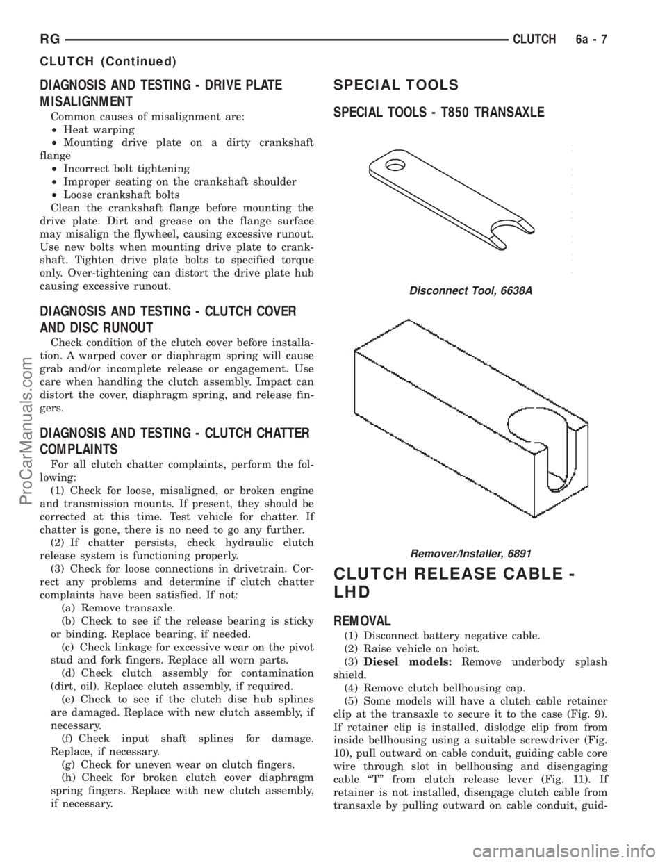
SPECIAL TOOLS - T850 TRANSAXLE
CLUTCH RELEASE CABLE -
LHD
REMOVAL
(1) Disconnect battery negative cable.
(2) Raise vehicle on hoist.
(3)Diesel models:Remove underbody splash
shield.
(4) Remove clutch bellhousing cap.
(5) Some models will have a clutch cable retainer
clip at the transaxle to secure it to the case (Fig. 9).
If retainer clip is installed, dislodge clip from from
inside bellhousing using a suitable screwdriver (Fig.
10), pull outward on cable conduit, guiding cable core
wire through slot in bellhousing and disengaging
cable ªTº from clutch release lever (Fig. 11). If
retainer is not installed, disengage clutch cable from
transaxle by pulling outward on cable conduit, guid-
Disconnect Tool, 6638A
Remover/Installer, 6891
RGCLUTCH6a-7
CLUTCH (Continued)
ProCarManuals.com
Page 266 of 2321
INSTALLATION
(1) Install modular clutch assembly to transaxle
input shaft (Fig. 31).
(2) Install transaxle to vehicle. (Refer to 21 -
TRANSMISSION/TRANSAXLE/MANUAL - INSTAL-
LATION)
SLAVE CYLINDER - RHD
REMOVAL
(1) Raise vehicle on hoist.Diesel models:Remove
underbody splash shield.
(2) Using Tool 6638A, disconnect hyrdraulic clutch
circuit quick connect fitting.
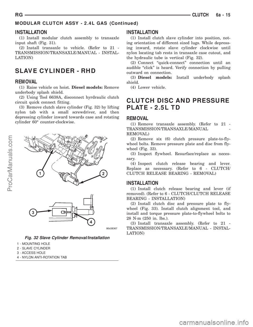
(3) Remove clutch slave cylinder (Fig. 32) by lifting
nylon tab with a small screwdriver, and then
depressing cylinder inward towards case and rotating
cylinder 60É counter-clockwise.
INSTALLATION
(1) Install clutch slave cylinder into position, not-
ing orientation of different sized lugs. While depress-
ing inward, rotate slave cylinder clockwise until
nylon locating tab rests in transaxle case cutout, and
the hydraulic tube is vertical (Fig. 32).
(2) Connect ªquick-connectº connection until an
audible ªclickº is heard. Verify connection by pulling
outward on connection.
(3)Diesel models:Install underbody splash
shield.
(4) Lower vehicle.
CLUTCH DISC AND PRESSURE
PLATE - 2.5L TD
REMOVAL
(1) Remove transaxle assembly. (Refer to 21 -
TRANSMISSION/TRANSAXLE/MANUAL -
REMOVAL)
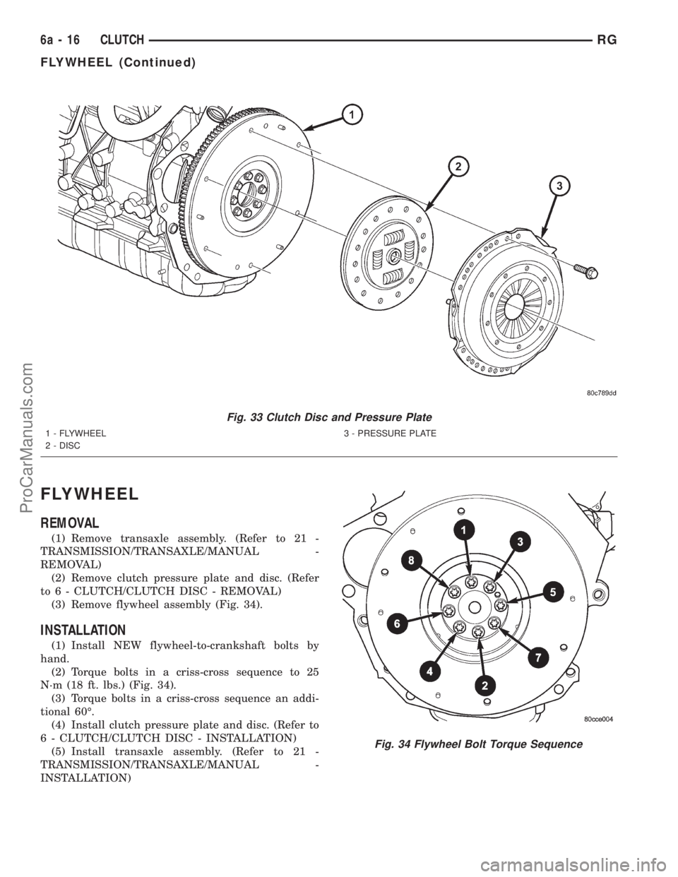
(2) Remove six (6) clutch pressure plate-to-fly-
wheel bolts. Remove pressure plate and disc from fly-
wheel (Fig. 33).
(3) Inspect flywheel. Resurface/replace as neces-
sary.
(4) Inspect clutch release bearing and lever.
Replace as necessary. (Refer to 6 - CLUTCH/
CLUTCH RELEASE BEARING - REMOVAL)
INSTALLATION
(1) Install clutch release bearing and lever (if
removed). (Refer to 6 - CLUTCH/CLUTCH RELEASE
BEARING - INSTALLATION)
(2) Install clutch disc and pressure plate to fly-
wheel (Fig. 33). Install clutch alignment tool, and
install and torque pressure plate-to-flywheel bolts to
28 N´m (250 in. lbs.).
(3) Install transaxle assembly. (Refer to 21 -
TRANSMISSION/TRANSAXLE/MANUAL - INSTAL-
LATION)
Fig. 32 Slave Cylinder Removal/Installation
1 - MOUNTING HOLE
2 - SLAVE CYLINDER
3 - ACCESS HOLE
4 - NYLON ANTI-ROTATION TAB
RGCLUTCH6a-15
MODULAR CLUTCH ASSY - 2.4L GAS (Continued)
ProCarManuals.com
Page 267 of 2321
FLYWHEEL
REMOVAL
(1) Remove transaxle assembly. (Refer to 21 -
TRANSMISSION/TRANSAXLE/MANUAL -
REMOVAL)
(2) Remove clutch pressure plate and disc. (Refer
to 6 - CLUTCH/CLUTCH DISC - REMOVAL)
(3) Remove flywheel assembly (Fig. 34).
INSTALLATION
(1) Install NEW flywheel-to-crankshaft bolts by
hand.
(2) Torque bolts in a criss-cross sequence to 25
N´m (18 ft. lbs.) (Fig. 34).
(3) Torque bolts in a criss-cross sequence an addi-
tional 60É.
(4) Install clutch pressure plate and disc. (Refer to
6 - CLUTCH/CLUTCH DISC - INSTALLATION)
(5) Install transaxle assembly. (Refer to 21 -
TRANSMISSION/TRANSAXLE/MANUAL -
INSTALLATION)
Fig. 33 Clutch Disc and Pressure Plate
1 - FLYWHEEL
2 - DISC3 - PRESSURE PLATE
Fig. 34 Flywheel Bolt Torque Sequence
6a - 16 CLUTCHRG
FLYWHEEL (Continued)
ProCarManuals.com
Page 360 of 2321

OPERATION
The Body Control Module (BCM) is designed to
control and integrate many of the electronic features
and functions of the vehicle. The microprocessor-
based BCM hardware and software monitors many
hard wired switch and sensor inputs as well as those
resources it shares with other electronic modules in
the vehicle through its communication over the PCI
data bus network. The internal programming and all
of these inputs allow the BCM microprocessor to
determine the tasks it needs to perform and their
priorities, as well as both the standard and optional
features that it should provide. The BCM program-
ming then performs those tasks and provides those
features through both PCI data bus communication
with other electronic modules and through hard
wired low current outputs to a number of relays.
These relays provide the BCM with the ability to
control numerous high current accessory systems in
the vehicle.
The BCM monitors its own internal circuitry as
well as many of its input and output circuits, and
will store a Diagnostic Trouble Code (DTC) in elec-
tronic memory for any failure it detects. These DTCs
can be retrieved and diagnosed using a DRBIIItscan
tool. Refer to the appropriate diagnostic information.
REMOVAL
(1) Disconnect and isolate the battery negative
cable.
(2) Remove lower steering column cover and knee
blocker reinforcement.
(3) Disconnect two wire connectors from bottom of
Body Control Module (BCM)
(4) Remove bolts holding the BCM to the dash
panel mounting bracket.
(5) Remove the BCM from the mounting bracket.
INSTALLATION
(1) Install the BCM onto the mounting bracket.
(2) Install the bolts holding the BCM to dash
panel mounting bracket.
(3) Connect two wire connectors to the bottom of
the BCM.
(4) Install the lower steering column cover and
knee blocker reinforcement.
(5) Connect the battery negative cable.
CONTROLLER ANTILOCK
BRAKE
DESCRIPTION
The controller antilock brake (CAB) is a micropro-
cessor-based device which monitors the antilock
brake system (ABS) during normal braking and con-trols it when the vehicle is in an ABS stop. The CAB
is mounted to the HCU as part of the integrated con-
trol unit (ICU) (Fig. 1). The CAB uses a 24-way elec-
trical connector on the vehicle wiring harness. The
power source for the CAB is through the ignition
switch in the RUN or ON position. The CAB is on
the PCI bus.
OPERATION
The primary functions of the controller antilock
brake (CAB) are to:
²Monitor the antilock brake system for proper
operation.
²Detect wheel locking or wheel slipping tenden-
cies by monitoring the speed of all four wheels of the
vehicle.
²Control fluid modulation to the wheel brakes
while the system is in an ABS mode.
²Store diagnostic information.
²Provide communication to the DRBIIItscan tool
while in diagnostic mode.
²Illuminate the amber ABS warning indicator
lamp.
²(With traction control only) Illuminate the TRAC
ON lamp in the message center on the instrument
panel when a traction control event occurs.
²(with traction control only) Illuminate the TRAC
OFF lamp when the amber ABS warning indicator
lamp illuminates.
The CAB constantly monitors the antilock brake
system for proper operation. If the CAB detects a
fault, it will turn on the amber ABS warning indica-
tor lamp and disable the antilock braking system.
Fig. 1 INTEGRATED CONTROL UNIT (ICU)
1 - PUMP/MOTOR
2 - HCU
3 - PUMP/MOTOR CONNECTOR
4 - CAB
RSELECTRONIC CONTROL MODULES8E-3
BODY CONTROL MODULE (Continued)
ProCarManuals.com
Page 421 of 2321
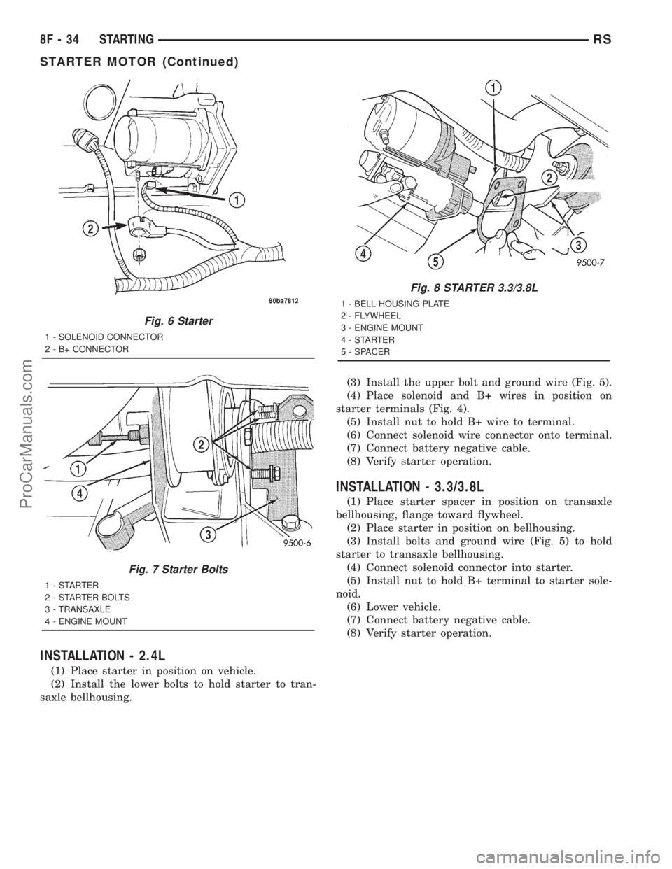
INSTALLATION - 2.4L
(1) Place starter in position on vehicle.
(2) Install the lower bolts to hold starter to tran-
saxle bellhousing.(3) Install the upper bolt and ground wire (Fig. 5).
(4) Place solenoid and B+ wires in position on
starter terminals (Fig. 4).
(5) Install nut to hold B+ wire to terminal.
(6) Connect solenoid wire connector onto terminal.
(7) Connect battery negative cable.
(8) Verify starter operation.
INSTALLATION - 3.3/3.8L
(1) Place starter spacer in position on transaxle
bellhousing, flange toward flywheel.
(2) Place starter in position on bellhousing.
(3) Install bolts and ground wire (Fig. 5) to hold
starter to transaxle bellhousing.
(4) Connect solenoid connector into starter.
(5) Install nut to hold B+ terminal to starter sole-
noid.
(6) Lower vehicle.
(7) Connect battery negative cable.
(8) Verify starter operation.
Fig. 6 Starter
1 - SOLENOID CONNECTOR
2 - B+ CONNECTOR
Fig. 7 Starter Bolts
1-STARTER
2 - STARTER BOLTS
3 - TRANSAXLE
4 - ENGINE MOUNT
Fig. 8 STARTER 3.3/3.8L
1 - BELL HOUSING PLATE
2 - FLYWHEEL
3 - ENGINE MOUNT
4-STARTER
5 - SPACER
8F - 34 STARTINGRS
STARTER MOTOR (Continued)
ProCarManuals.com
Page 456 of 2321

INSTALLATION - 3.3/3.8L
(1) Install coil over studs on bracket.
(2) Install 2 bolts to ignition coil.
(3) Install 2 nuts to the ignition coil studs. Tighten
nuts and bolts.
(4) Connect the electrical connector to the ignition
coil.
(5) Install the ignition cables to the ignition coil.
(6) Reposition the Power steering reservoir. Slide
bracket over the mounting stud (Fig. 12).
(7) Install 2 bolts the Power steering reservoir to
intake manifold.
(8) Tighten the lower nut to stud on ignition coil
bracket.
(9) Install the throttle and speed control cables to
clip.
(10) Connect the negative battery cable.
KNOCK SENSOR
DESCRIPTION
The knock sensor threads into the cylinder block.
The knock sensor is designed to detect engine vibra-
tion that is caused by detonation.
OPERATION
When the knock sensor detects a knock in one of
the cylinders, it sends an input signal to the PCM. In
response, the PCM retards ignition timing for all cyl-
inders by a scheduled amount.Knock sensors contain a piezoelectric material
which constantly vibrates and sends an input voltage
(signal) to the PCM while the engine operates. As the
intensity of the crystal's vibration increases, the
knock sensor output voltage also increases.
The voltage signal produced by the knock sensor
increases with the amplitude of vibration. The PCM
receives as an input the knock sensor voltage signal.
If the signal rises above a predetermined level, the
PCM will store that value in memory and retard
ignition timing to reduce engine knock. If the knock
sensor voltage exceeds a preset value, the PCM
retards ignition timing for all cylinders. It is not a
selective cylinder retard.
The PCM ignores knock sensor input during engine
idle conditions. Once the engine speed exceeds a
specified value, knock retard is allowed.
Knock retard uses its own short term and long
term memory program.
Long term memory stores previous detonation
information in its battery-backed RAM. The maxi-
mum authority that long term memory has over tim-
ing retard can be calibrated.
Short term memory is allowed to retard timing up
to a preset amount under all operating conditions (as
long as rpm is above the minimum rpm) except WOT.
The PCM, using short term memory, can respond
quickly to retard timing when engine knock is
detected. Short term memory is lost any time the
ignition key is turned off.
NOTE: Over or under tightening affects knock sen-
sor performance, possibly causing improper spark
control.
REMOVAL - 2.4L
The knock sensor threads into the side of the cyl-
inder block in front of the starter (Fig. 13).
(1) Disconnect electrical connector from knock sen-
sor.
(2) Use a crow foot socket to remove the knock
sensors.
REMOVAL - 3.8L
The knock sensor threads into the side of the cyl-
inder block in the rear.
(1) Disconnect the negative battery cable.
(2) Raise vehicle and support.
(3) On All Wheel Drive vehicles remove the PTU
(Power Transfer Unit), refer to the Transmission sec-
tion for more information.
(4) Disconnect electrical connector from knock sen-
sor.
(5) Use a crow foot socket to remove the knock
sensor.
Fig. 12 IGNITION COIL BRACKET 3.3/3.8L
RSIGNITION CONTROL8I-7
IGNITION COIL (Continued)
ProCarManuals.com
Page 584 of 2321

The components above must be replaced because
they cannot be reused. Replace any other driver air-
bag system components if damaged.
REMOVAL
DEPLOYED AIRBAG
The Driver Airbag and Driver Airbag Cover/Horn
Pad are serviced separately from each other.
(1) Clean powder residue from interior of vehicle,
(Refer to 8 - ELECTRICAL/RESTRAINTS/DRIVER
AIRBAG - STANDARD PROCEDURE ) Cleanup.
(2) Remove two screws attaching Driver Airbag to
steering wheel.
(3) Remove the driver airbag from steering wheel.
(4) Disconnect wire connectors from Airbag and
Clock Spring.
(5) Adjust the steering wheel so that the tires are
in a straight ahead position. Remove steering wheel,
(Refer to 19 - STEERING/COLUMN/STEERING
WHEEL - REMOVAL)
(6) Disconnect the 2-way and 4-way connectors
between the clock spring and the instrument panel
wiring harness.
(7) Remove upper and lower steering column
shrouds.
(8) Remove clock spring from the housing assem-
bly by depressing the 2 tabs on the clock spring.
UNDEPLOYED AIRBAG
(1) Remove screws attaching airbag/horn switch to
steering wheel.
(2) Remove Driver Airbag from steering wheel.
(3) Disconnect wire connectors from driver airbag
and clock spring.
INSTALLATION
DEPLOYED AIRBAG
(1) Perform cleanup procedure.(Refer to 8 - ELEC-
TRICAL/RESTRAINTS/DRIVER AIRBAG - STAN-
DARD PROCEDURE)
(2) Install a new steering column assembly and
lower steering column coupler. Refer to Steering, Col-
umn, Installation.
(3) Install the clock spring.
(4) Install the driver airbag and the two screws
retaining the airbag. Tighten screws to 10 N´m (90
in. lbs.)
WARNING: DO NOT CONNECT THE BATTERY NEGA-
TIVE CABLE. REFER TO ELECTRICAL, RESTRAINTS,
DIAGNOSIS AND TESTING - AIRBAG SYSTEM FIRST.
UNDEPLOYED AIRBAG
(1) Position a new airbag into the airbag cavity.(2) Install the two screws retaining the airbag.
Tighten screws to 10 N´m (90 in. lbs.)
WARNING: DO NOT CONNECT THE BATTERY NEGA-
TIVE CABLE. REFER TO ELECTRICAL, RESTRAINTS,
DIAGNOSIS AND TESTING - AIRBAG SYSTEM FIRST.
OCCUPANT RESTRAINT
CONTROLLER
DESCRIPTION
The front driver and passenger airbag system is
designed to reduce the risk of fatality or serious
injury, caused by a frontal impact of the vehicle.
The Occupant Restraint Controller (ORC) contains
the impact sensor and energy reserve capacitor. It is
mounted on a bracket, under the instrument panel,
just forward of the storage bin. The ORC monitors
the system to determine the system readiness. The
ORC contains on-board diagnostics and will light the
AIRBAG warning lamp in the message center when a
problem occurs.
OPERATION
The impact sensor provides verification of the
direction and severity of the impact. One impact sen-
sor is used. It is located inside the Occupant
Restraint Controller (ORC). The impact sensor is an
accelerometer that senses deceleration. The decelera-
tion pulses are sent to a microprocessor which con-
tains a decision algorithm. When an impact is severe
enough to require airbag protection, the ORC micro-
processor sends a signal that completes the electrical
circuit to the driver and passenger airbags. The
impact sensor is calibrated for the specific vehicle
and reacts to the severity and direction of an impact.
REMOVAL
(1)Disconnect and isolate the battery negative cable.
(2) Remove storage bin from instrument panel.
Refer to Body, Instrument Panel, Storage Bin,
Removal.
(3) Remove three bolts holding ORC to floor
bracket.
(4) Disconnect the wire connector from ORC.
(5) Remove the ORC w/bracket assembly from
vehicle.
INSTALLATION
WARNING: DO NOT INSTALL ORC IF MOUNTING
LOCATION IS DEFORMED OR DAMAGED.
RSRESTRAINTS8O-5
DRIVER AIRBAG (Continued)
ProCarManuals.com