2001 DODGE TOWN AND COUNTRY wheel bolts
[x] Cancel search: wheel boltsPage 1455 of 2321
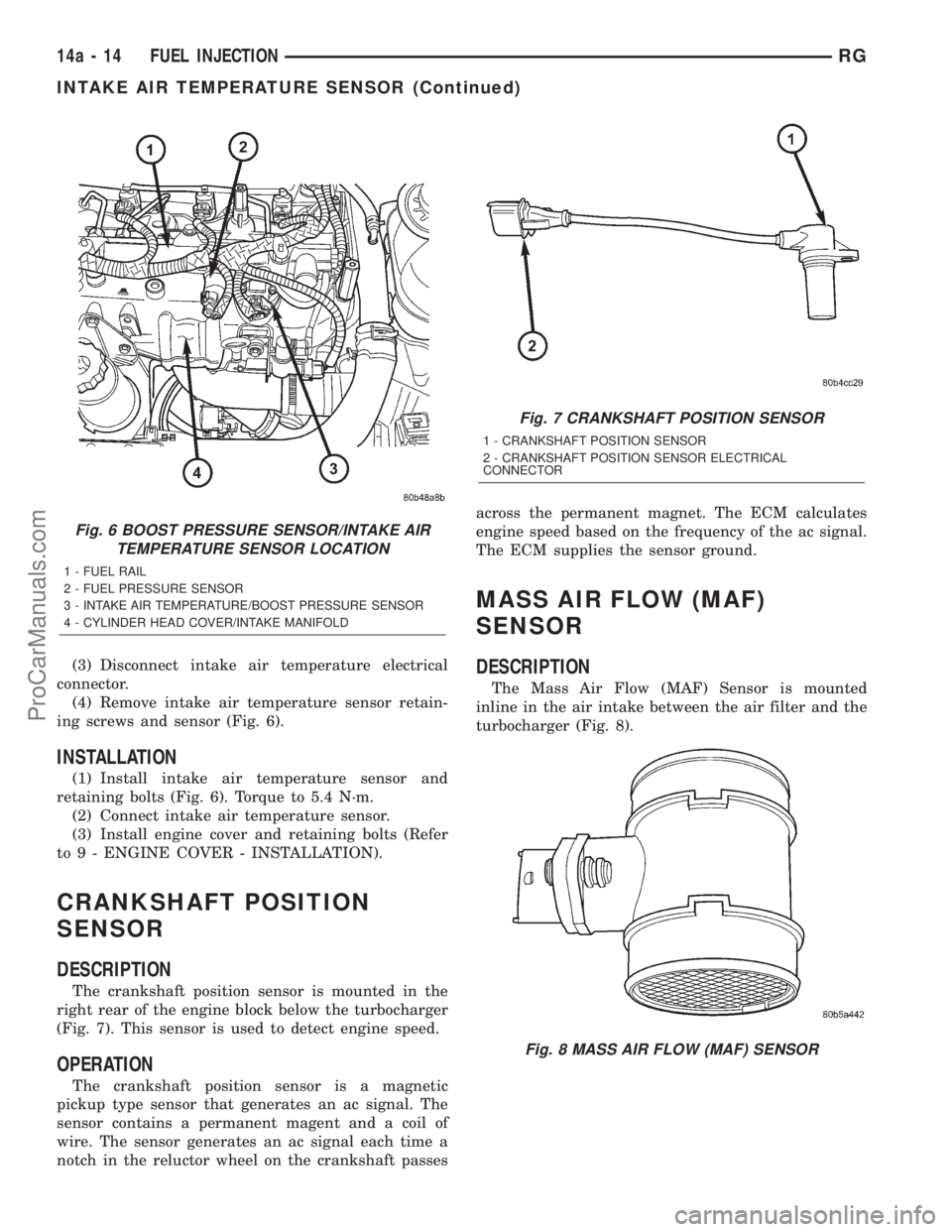
(3) Disconnect intake air temperature electrical
connector.
(4) Remove intake air temperature sensor retain-
ing screws and sensor (Fig. 6).
INSTALLATION
(1) Install intake air temperature sensor and
retaining bolts (Fig. 6). Torque to 5.4 N´m.
(2) Connect intake air temperature sensor.
(3) Install engine cover and retaining bolts (Refer
to 9 - ENGINE COVER - INSTALLATION).
CRANKSHAFT POSITION
SENSOR
DESCRIPTION
The crankshaft position sensor is mounted in the
right rear of the engine block below the turbocharger
(Fig. 7). This sensor is used to detect engine speed.
OPERATION
The crankshaft position sensor is a magnetic
pickup type sensor that generates an ac signal. The
sensor contains a permanent magent and a coil of
wire. The sensor generates an ac signal each time a
notch in the reluctor wheel on the crankshaft passesacross the permanent magnet. The ECM calculates
engine speed based on the frequency of the ac signal.
The ECM supplies the sensor ground.
MASS AIR FLOW (MAF)
SENSOR
DESCRIPTION
The Mass Air Flow (MAF) Sensor is mounted
inline in the air intake between the air filter and the
turbocharger (Fig. 8).
Fig. 6 BOOST PRESSURE SENSOR/INTAKE AIR
TEMPERATURE SENSOR LOCATION
1 - FUEL RAIL
2 - FUEL PRESSURE SENSOR
3 - INTAKE AIR TEMPERATURE/BOOST PRESSURE SENSOR
4 - CYLINDER HEAD COVER/INTAKE MANIFOLD
Fig. 7 CRANKSHAFT POSITION SENSOR
1 - CRANKSHAFT POSITION SENSOR
2 - CRANKSHAFT POSITION SENSOR ELECTRICAL
CONNECTOR
Fig. 8 MASS AIR FLOW (MAF) SENSOR
14a - 14 FUEL INJECTIONRG
INTAKE AIR TEMPERATURE SENSOR (Continued)
ProCarManuals.com
Page 1460 of 2321
NOTE: Power steering pump maximum relief pres-
sure is 9,653 to 10,342 kPa (1,400 to 1,500 psi.).
(9) Close analyzer valve fully three times and
record highest pressure indicated each time. All three
readings must be above specifications and within 345
kPa (50 psi) of each other.
²If power steering pump pressures are above
specifications, but not within 345 kPa (50 psi) of each
other, replace pump.
²If power steering pump pressures are within 345
kPa (50 psi) of each other, but are below specifica-
tions, replace pump.
CAUTION: Do not force the pump to operate against
the stops for more than 2 to 4 seconds at a time
because, pump damage will result.
(10) Completely open the valve on the Power
Steering Analyzer. Turn the steering wheel to theextreme left until the stop in the steering gear is
met, then turn the steering wheel to the right until
the right stop is met. Record the highest indicated
pressure at each position. Compare the recorded
readings to the specifications. If the highest output
pressures are not the same against either stop, the
steering gear is leaking internally and must be
replaced.
DIAGNOSIS AND TESTING - STEERING
SYSTEM DIAGNOSIS CHARTS
NOTE: There are three diagnosis charts following
that cover POWER STEERING NOISE, STEERING
WHEEL FEEL, and POWER STEERING FLUID.
POWER STEERING NOISE
CONDITION POSSIBLE CAUSES CORRECTION
OBJECTIONABLE HISS
OR WHISTLE*1. Damaged or mispositioned
steering column shaft/coupling dash
panel seal.1. Reposition or replace steering
column shaft/coupling dash panel seal.
2. Noisy valve in power steering
gear.2. Replace power steering gear.
3. Mis-routed power steering hose. 3. Check routing of power steering
hoses. Ensure hoses do not come in
unwanted contact with other
components and objects.
RATTLE OR CLUNK 1. Power steering gear loose on front
suspension crossmember.1. Inspect power steering gear
mounting bolts. Replace as necessary.
Tighten to the specified torque.
2. Front suspension crossmember
mounting fasteners loose at frame.2. Tighten the front suspension
crossmember mounting fasteners to the
specified torque.
3. Loose tie rod (outer or inner). 3. Check tie rod pivot points for wear.
Replace worn/loose parts as required.
4. Loose lower control arm mounting
bolts at front suspension
crossmember.4. Tighten control arm mounting bolts to
the specified torques.
5. Lower control arm pivot bushing
worn.5. Replace lower control arm pivot
bushing.
6. Loose strut assembly mounting
fasteners at tower.6. Tighten strut assembly fasteners to
the specified torque.
7. Power steering fluid pressure
hose touching the body of the
vehicle.7. Adjust hose to proper position by
loosening, repositioning, and tightening
fitting to specified torque. Do not bend
tubing.
RSSTEERING19-3
STEERING (Continued)
ProCarManuals.com
Page 1464 of 2321
CONDITION POSSIBLE CAUSES CORRECTION
3. Lack of lubrication causing binding
in front lower control arm ball joints.3. Lubricate ball joints if ball joints are not a
lubricated for life type of ball joint, then
inspect ball joint for wear, replace lower
control arm as necessary. If ball joint is a
lubricated for life ball joint, replace lower
control arm ball joint.
4. Steering column coupling joints
misaligned.4. Realign steering column coupling joints.
5. Steering wheel rubbing.** 5. Adjust steering column shrouds to
eliminate rubbing condition.
6. Damaged, mis-positioned or
un-lubricated steering column
coupler to dash seal.**6. Replace, reposition, or lubricate dash
seal.
7. Binding pivot bearing in front strut
assembly.7. Replace pivot bearing in front strut
assembly.
8. Binding shaft bearing in steering
column.8. Replace the steering column.
9. Excessive friction in steering
column coupling.9. Replace steering column coupling.
10. Excessive friction in power
steering gear.10. Replace power steering gear.
EXCESSIVE STEERING
WHEEL KICKBACK OR
TOO MUCH STEERING
WHEEL FREE PLAY.1. Air in the fluid of the power
steering system.1. Bleed air from system following the the
power steering pump initial operation
service procedure.*
2. Power steering gear loose on
cradle/crossmember.2. Inspect power steering gear mounting
bolts. Replace as necessary. Tighten to the
specified torque.
3. Steering column coupling or
intermediate shaft worn, broken or
loose.3. Replace steering column coupling or
intermediate shaft.
4. Free play in steering column. 4. Check all components of the steering
column and repair or replace as required.
5. Worn lower control arm ball joints. 5. Replace lower control arm ball joints as
required.
6. Loose steering knuckle-to-ball joint
stud pinch bolt.6. Inspect pinch bolt, replace as necessary,
and tighten to specified torque.
7. Front wheel bearing loose or
worn.7. Replace hub and bearing as necessary.
8. Loose outer tie rod end. 8. Replace outer tie rod end that has
excessive free play.
9. Loose inner tie rod. 9. Replace power steering gear.
10. Defective steering gear rotary
valve.10. Replace power steering gear.
NOTE: * Steering shudder can be expected in new
vehicles and vehicles with recent steering systemrepairs. Shudder should dissipate after the vehicle
has been driven several weeks.
RSSTEERING19-7
STEERING (Continued)
ProCarManuals.com
Page 1467 of 2321
COLUMN
TABLE OF CONTENTS
page page
COLUMN
DESCRIPTION...........................10
WARNING..............................10
DIAGNOSIS AND TESTING.................12
STEERING COLUMN....................12
REMOVAL..............................12
INSTALLATION...........................13
SPECIFICATIONS........................14
KEY/LOCK CYLINDER
DESCRIPTION...........................14OPERATION.............................14
REMOVAL..............................14
INSTALLATION...........................14
GEAR SHIFT LEVER
REMOVAL..............................15
INSTALLATION...........................15
SHROUD
REMOVAL..............................16
INSTALLATION...........................16
COLUMN
DESCRIPTION - STEERING COLUMN
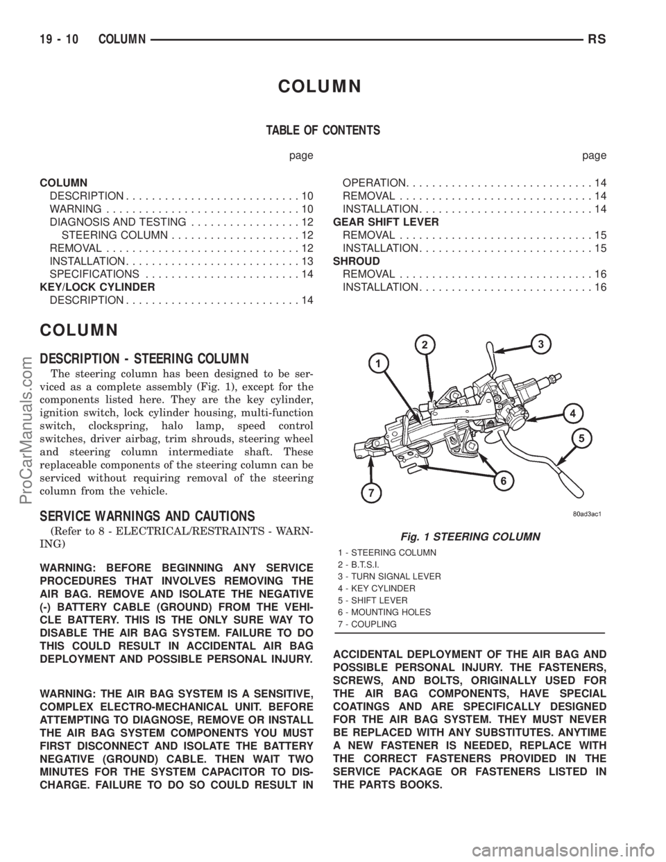
The steering column has been designed to be ser-
viced as a complete assembly (Fig. 1), except for the
components listed here. They are the key cylinder,
ignition switch, lock cylinder housing, multi-function
switch, clockspring, halo lamp, speed control
switches, driver airbag, trim shrouds, steering wheel
and steering column intermediate shaft. These
replaceable components of the steering column can be
serviced without requiring removal of the steering
column from the vehicle.
SERVICE WARNINGS AND CAUTIONS
(Refer to 8 - ELECTRICAL/RESTRAINTS - WARN-
ING)
WARNING: BEFORE BEGINNING ANY SERVICE
PROCEDURES THAT INVOLVES REMOVING THE
AIR BAG. REMOVE AND ISOLATE THE NEGATIVE
(-) BATTERY CABLE (GROUND) FROM THE VEHI-
CLE BATTERY. THIS IS THE ONLY SURE WAY TO
DISABLE THE AIR BAG SYSTEM. FAILURE TO DO
THIS COULD RESULT IN ACCIDENTAL AIR BAG
DEPLOYMENT AND POSSIBLE PERSONAL INJURY.
WARNING: THE AIR BAG SYSTEM IS A SENSITIVE,
COMPLEX ELECTRO-MECHANICAL UNIT. BEFORE
ATTEMPTING TO DIAGNOSE, REMOVE OR INSTALL
THE AIR BAG SYSTEM COMPONENTS YOU MUST
FIRST DISCONNECT AND ISOLATE THE BATTERY
NEGATIVE (GROUND) CABLE. THEN WAIT TWO
MINUTES FOR THE SYSTEM CAPACITOR TO DIS-
CHARGE. FAILURE TO DO SO COULD RESULT INACCIDENTAL DEPLOYMENT OF THE AIR BAG AND
POSSIBLE PERSONAL INJURY. THE FASTENERS,
SCREWS, AND BOLTS, ORIGINALLY USED FOR
THE AIR BAG COMPONENTS, HAVE SPECIAL
COATINGS AND ARE SPECIFICALLY DESIGNED
FOR THE AIR BAG SYSTEM. THEY MUST NEVER
BE REPLACED WITH ANY SUBSTITUTES. ANYTIME
A NEW FASTENER IS NEEDED, REPLACE WITH
THE CORRECT FASTENERS PROVIDED IN THE
SERVICE PACKAGE OR FASTENERS LISTED IN
THE PARTS BOOKS.Fig. 1 STEERING COLUMN
1 - STEERING COLUMN
2 - B.T.S.I.
3 - TURN SIGNAL LEVER
4 - KEY CYLINDER
5 - SHIFT LEVER
6 - MOUNTING HOLES
7 - COUPLING
19 - 10 COLUMNRS
ProCarManuals.com
Page 1475 of 2321
ing gear. This travel pushes and pulls the tie rods to
change the direction of the vehicle's front wheels.
Power assist steering provided by the power steer-
ing pump is controlled by an open center, rotary type
control valve which directs oil from the pump to
either side of the integral rack piston upon demand.
Road feel is controlled by the diameter of a torsion
bar which initially steers the vehicle. As required
steering effort increases, as in a turn, the torsion bar
twists, causing relative rotary motion between the
rotary valve body and the valve spool. This move-
ment directs oil behind the integral rack piston
which, in turn, builds up hydraulic pressure and
assists in the turning effort.
Manual steering control of the vehicle can be main-
tained if power steering assist is lost. However,
under this condition, steering effort is significantly
increased.
SERVICE WARNINGS AND CAUTIONS
WARNING: POWER STEERING FLUID, ENGINE
PARTS AND EXHAUST SYSTEM MAY BE
EXTREMELY HOT IF ENGINE HAS BEEN RUNNING.
DO NOT START ENGINE WITH ANY LOOSE OR DIS-
CONNECTED HOSES. DO NOT ALLOW HOSES TO
TOUCH HOT EXHAUST MANIFOLD OR CATALYST.
WARNING: FLUID LEVEL SHOULD BE CHECKED
WITH THE ENGINE OFF TO PREVENT PERSONAL
INJURY FROM MOVING PARTS.
CAUTION: When the system is open, cap all open
ends of the hoses, power steering pump fittings or
power steering gear ports to prevent entry of for-
eign material into the components.
REMOVAL - GEAR
CAUTION: Positioning the steering column in the
locked position will prevent the clockspring from
being accidentally over-extended when the steering
column is disconnected from the intermediate
steering coupler.
(1) Remove cap from power steering fluid reser-
voir.
(2) Using a siphon pump, remove as much fluid as
possible from the power steering fluid reservoir.
(3) With the ignition key in the locked position
turn the steering wheel to the left until the steering
wheel is in the locked position.
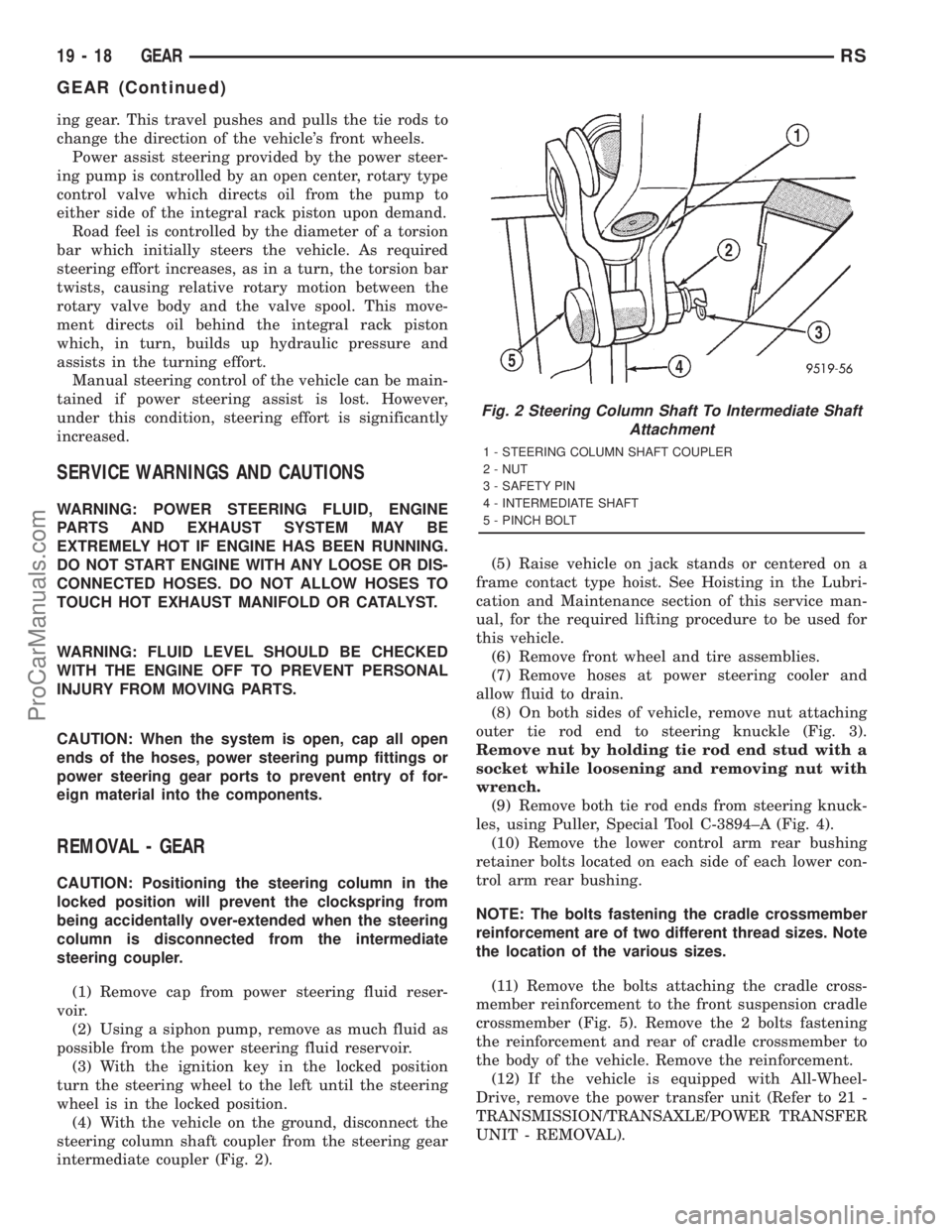
(4) With the vehicle on the ground, disconnect the
steering column shaft coupler from the steering gear
intermediate coupler (Fig. 2).(5) Raise vehicle on jack stands or centered on a
frame contact type hoist. See Hoisting in the Lubri-
cation and Maintenance section of this service man-
ual, for the required lifting procedure to be used for
this vehicle.
(6) Remove front wheel and tire assemblies.
(7) Remove hoses at power steering cooler and
allow fluid to drain.
(8) On both sides of vehicle, remove nut attaching
outer tie rod end to steering knuckle (Fig. 3).
Remove nut by holding tie rod end stud with a
socket while loosening and removing nut with
wrench.
(9) Remove both tie rod ends from steering knuck-
les, using Puller, Special Tool C-3894±A (Fig. 4).
(10) Remove the lower control arm rear bushing
retainer bolts located on each side of each lower con-
trol arm rear bushing.
NOTE: The bolts fastening the cradle crossmember
reinforcement are of two different thread sizes. Note
the location of the various sizes.
(11) Remove the bolts attaching the cradle cross-
member reinforcement to the front suspension cradle
crossmember (Fig. 5). Remove the 2 bolts fastening
the reinforcement and rear of cradle crossmember to
the body of the vehicle. Remove the reinforcement.
(12) If the vehicle is equipped with All-Wheel-
Drive, remove the power transfer unit (Refer to 21 -
TRANSMISSION/TRANSAXLE/POWER TRANSFER
UNIT - REMOVAL).
Fig. 2 Steering Column Shaft To Intermediate Shaft
Attachment
1 - STEERING COLUMN SHAFT COUPLER
2 - NUT
3 - SAFETY PIN
4 - INTERMEDIATE SHAFT
5 - PINCH BOLT
19 - 18 GEARRS
GEAR (Continued)
ProCarManuals.com
Page 1478 of 2321
(4) Install steering gear assembly on the front sus-
pension cradle. Install the 3 steering gear mounting
bolts and nuts (Fig. 7).
CAUTION: Proper torque on the steering gear to
suspension cradle mounting bolts is very impor-
tant.
(5) Tighten the 3 steering gear to suspension cra-
dle mounting bolts to a torque of 183 N´m (135 ft.
lbs.).
(6) Attach the power steering fluid pressure and
return lines (Fig. 6) to the proper fittings on the
steering gear. Tighten the power steering fluid line
tube nuts to a torque of 31 N´m (275 in. lbs.).
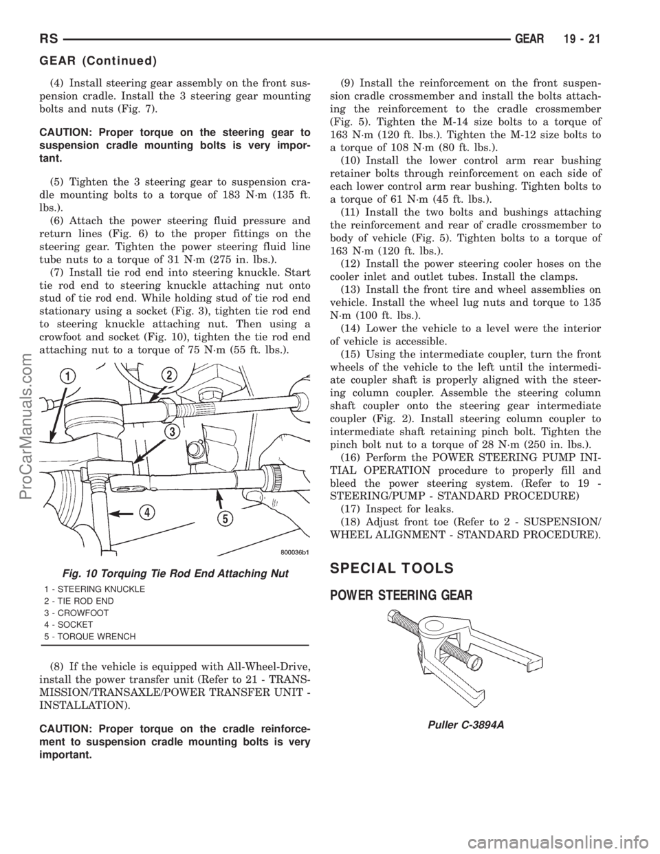
(7) Install tie rod end into steering knuckle. Start
tie rod end to steering knuckle attaching nut onto
stud of tie rod end. While holding stud of tie rod end
stationary using a socket (Fig. 3), tighten tie rod end
to steering knuckle attaching nut. Then using a
crowfoot and socket (Fig. 10), tighten the tie rod end
attaching nut to a torque of 75 N´m (55 ft. lbs.).
(8) If the vehicle is equipped with All-Wheel-Drive,
install the power transfer unit (Refer to 21 - TRANS-
MISSION/TRANSAXLE/POWER TRANSFER UNIT -
INSTALLATION).
CAUTION: Proper torque on the cradle reinforce-
ment to suspension cradle mounting bolts is very
important.(9) Install the reinforcement on the front suspen-
sion cradle crossmember and install the bolts attach-
ing the reinforcement to the cradle crossmember
(Fig. 5). Tighten the M-14 size bolts to a torque of
163 N´m (120 ft. lbs.). Tighten the M-12 size bolts to
a torque of 108 N´m (80 ft. lbs.).
(10) Install the lower control arm rear bushing
retainer bolts through reinforcement on each side of
each lower control arm rear bushing. Tighten bolts to
a torque of 61 N´m (45 ft. lbs.).
(11) Install the two bolts and bushings attaching
the reinforcement and rear of cradle crossmember to
body of vehicle (Fig. 5). Tighten bolts to a torque of
163 N´m (120 ft. lbs.).
(12) Install the power steering cooler hoses on the
cooler inlet and outlet tubes. Install the clamps.
(13) Install the front tire and wheel assemblies on
vehicle. Install the wheel lug nuts and torque to 135
N´m (100 ft. lbs.).
(14) Lower the vehicle to a level were the interior
of vehicle is accessible.
(15) Using the intermediate coupler, turn the front
wheels of the vehicle to the left until the intermedi-
ate coupler shaft is properly aligned with the steer-
ing column coupler. Assemble the steering column
shaft coupler onto the steering gear intermediate
coupler (Fig. 2). Install steering column coupler to
intermediate shaft retaining pinch bolt. Tighten the
pinch bolt nut to a torque of 28 N´m (250 in. lbs.).
(16) Perform the POWER STEERING PUMP INI-
TIAL OPERATION procedure to properly fill and
bleed the power steering system. (Refer to 19 -
STEERING/PUMP - STANDARD PROCEDURE)
(17) Inspect for leaks.
(18) Adjust front toe (Refer to 2 - SUSPENSION/
WHEEL ALIGNMENT - STANDARD PROCEDURE).
SPECIAL TOOLS
POWER STEERING GEARFig. 10 Torquing Tie Rod End Attaching Nut
1 - STEERING KNUCKLE
2 - TIE ROD END
3 - CROWFOOT
4 - SOCKET
5 - TORQUE WRENCH
Puller C-3894A
RSGEAR19-21
GEAR (Continued)
ProCarManuals.com
Page 1482 of 2321
SERVICE WARNINGS AND CAUTIONS
WARNING: POWER STEERING FLUID, ENGINE
PARTS AND EXHAUST SYSTEM MAY BE
EXTREMELY HOT IF ENGINE HAS BEEN RUNNING.
DO NOT START ENGINE WITH ANY LOOSE OR DIS-
CONNECTED HOSES. DO NOT ALLOW HOSES TO
TOUCH HOT EXHAUST MANIFOLD OR CATALYST.
WARNING: FLUID LEVEL SHOULD BE CHECKED
WITH THE ENGINE OFF TO PREVENT PERSONAL
INJURY FROM MOVING PARTS.
CAUTION: When the system is open, cap all open
ends of the hoses, power steering pump fittings or
power steering gear ports to prevent entry of for-
eign material into the components.
STANDARD PROCEDURE - POWER STEERING
PUMP INITIAL OPERATION
CAUTION: The fluid level should be checked with
engine off to prevent injury from moving compo-
nents. Use only MoparTPower Steering Fluid (MS-
5931) or approved equivalent. Do not overfill.
Read the fluid level through the side of the power
steering fluid reservoir. The fluid level should indi-
cateªFILL RANGEºwhen the fluid is at a temper-
ature of approximately 21ÉC to 27ÉC (70ÉF to 80ÉF).
(1) Wipe the filler cap and area clean, then remove
the cap.
(2) Fill the fluid reservoir to the proper level and
let the fluid settle for at least two (2) minutes.
(3) Start the engine and let run for a few seconds,
then turn the engine off.
(4) Add fluid if necessary. Repeat the above steps
until the fluid level remains constant after running
the engine.
(5) Raise the front wheels off the ground.
(6) Start the engine.
(7) Slowly turn the steering wheel right and left,
lightly contacting the wheel stops.
(8) Add fluid if necessary.
(9) Lower the vehicle, then turn the steering wheel
slowly from lock-to-lock.
(10) Stop the engine. Check the fluid level and
refill as required.
(11) If the fluid is extremely foamy, allow the vehi-
cle to stabilize a few minutes, then repeat the above
procedure.
REMOVAL - PUMP (2.4L ENGINE)
(1) Remove the (-) negative battery cable from the
battery and isolate cable.
(2) Remove the cap from the power steering fluid
reservoir.
(3) Using a siphon pump, remove as much power
steering fluid as possible from the power steering
fluid reservoir.
(4) Raise the vehicle on jack stands or centered on
a frame contact type hoist. See Hoisting in Lubrica-
tion and Maintenance.
(5) Disconnect the oxygen sensor wiring harness
from the vehicle wiring harness at the rear engine
mount bracket.
NOTE: The exhaust system needs to be removed
from the engine to allow for an area to remove the
power steering pump from the vehicle.
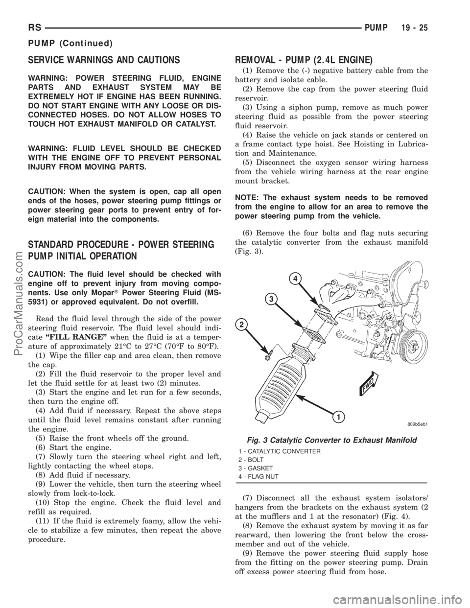
(6) Remove the four bolts and flag nuts securing
the catalytic converter from the exhaust manifold
(Fig. 3).
(7) Disconnect all the exhaust system isolators/
hangers from the brackets on the exhaust system (2
at the mufflers and 1 at the resonator) (Fig. 4).
(8) Remove the exhaust system by moving it as far
rearward, then lowering the front below the cross-
member and out of the vehicle.
(9) Remove the power steering fluid supply hose
from the fitting on the power steering pump. Drain
off excess power steering fluid from hose.
Fig. 3 Catalytic Converter to Exhaust Manifold
1 - CATALYTIC CONVERTER
2 - BOLT
3 - GASKET
4 - FLAG NUT
RSPUMP19-25
PUMP (Continued)
ProCarManuals.com
Page 1490 of 2321
STEERING
TABLE OF CONTENTS
page page
GEAR..................................1PUMP..................................6
GEAR
TABLE OF CONTENTS
page page
GEAR
REMOVAL...............................1INSTALLATION............................4
GEAR
REMOVAL - RHD GEAR
CAUTION: Positioning the steering column in the
locked position will prevent the clockspring from
being accidentally over-extended when the steering
column is disconnected from the intermediate
steering coupler.
(1) Remove cap from power steering fluid reser-
voir.
(2) Using a siphon pump, remove as much fluid as
possible from the power steering fluid reservoir.
(3) With the ignition key in the locked position
turn the steering wheel to the left until the steering
wheel is in the locked position.
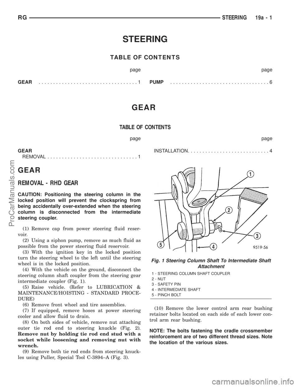
(4) With the vehicle on the ground, disconnect the
steering column shaft coupler from the steering gear
intermediate coupler (Fig. 1).
(5) Raise vehicle. (Refer to LUBRICATION &
MAINTENANCE/HOISTING - STANDARD PROCE-
DURE)
(6) Remove front wheel and tire assemblies.
(7) If equipped, remove hoses at power steering
cooler and allow fluid to drain.
(8) On both sides of vehicle, remove nut attaching
outer tie rod end to steering knuckle (Fig. 2).
Remove nut by holding tie rod end stud with a
socket while loosening and removing nut with
wrench.
(9) Remove both tie rod ends from steering knuck-
les using Puller, Special Tool C-3894±A (Fig. 3).(10) Remove the lower control arm rear bushing
retainer bolts located on each side of each lower con-
trol arm rear bushing.
NOTE: The bolts fastening the cradle crossmember
reinforcement are of two different thread sizes. Note
the location of the various sizes.
Fig. 1 Steering Column Shaft To Intermediate Shaft
Attachment
1 - STEERING COLUMN SHAFT COUPLER
2 - NUT
3 - SAFETY PIN
4 - INTERMEDIATE SHAFT
5 - PINCH BOLT
RGSTEERING19a-1
ProCarManuals.com