2001 DODGE TOWN AND COUNTRY weight
[x] Cancel search: weightPage 2 of 2321
INTRODUCTION
TABLE OF CONTENTS
page page
VEHICLE SAFETY CERTIFICATION LABEL
DESCRIPTION............................1
VEHICLE IDENTIFICATION NUMBER
DESCRIPTION............................1
VECI LABEL
DESCRIPTION............................3
BODY CODE PLATE
DESCRIPTION............................3
INTERNATIONAL SYMBOLS
DESCRIPTION............................4FASTENER IDENTIFICATION
DESCRIPTION............................5
FASTENER USAGE
DESCRIPTION............................5
METRIC SYSTEM
DESCRIPTION............................8
TORQUE REFERENCES
DESCRIPTION...........................10
VEHICLE SAFETY
CERTIFICATION LABEL
DESCRIPTION
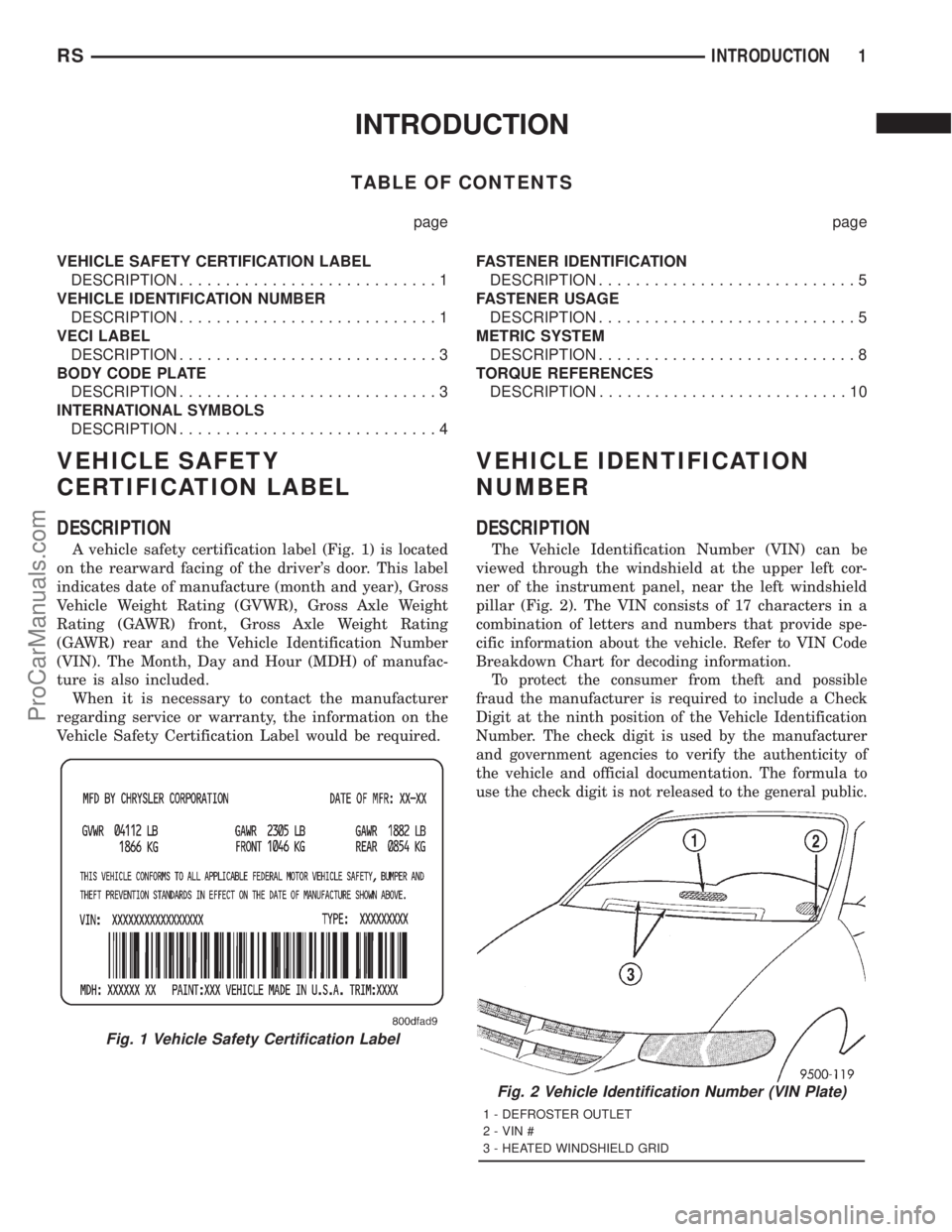
A vehicle safety certification label (Fig. 1) is located
on the rearward facing of the driver's door. This label
indicates date of manufacture (month and year), Gross
Vehicle Weight Rating (GVWR), Gross Axle Weight
Rating (GAWR) front, Gross Axle Weight Rating
(GAWR) rear and the Vehicle Identification Number
(VIN). The Month, Day and Hour (MDH) of manufac-
ture is also included.
When it is necessary to contact the manufacturer
regarding service or warranty, the information on the
Vehicle Safety Certification Label would be required.
VEHICLE IDENTIFICATION
NUMBER
DESCRIPTION
The Vehicle Identification Number (VIN) can be
viewed through the windshield at the upper left cor-
ner of the instrument panel, near the left windshield
pillar (Fig. 2). The VIN consists of 17 characters in a
combination of letters and numbers that provide spe-
cific information about the vehicle. Refer to VIN Code
Breakdown Chart for decoding information.
To protect the consumer from theft and possible
fraud the manufacturer is required to include a Check
Digit at the ninth position of the Vehicle Identification
Number. The check digit is used by the manufacturer
and government agencies to verify the authenticity of
the vehicle and official documentation. The formula to
use the check digit is not released to the general public.
Fig. 1 Vehicle Safety Certification Label
Fig. 2 Vehicle Identification Number (VIN Plate)
1 - DEFROSTER OUTLET
2 - VIN #
3 - HEATED WINDSHIELD GRID
RSINTRODUCTION1
ProCarManuals.com
Page 3 of 2321
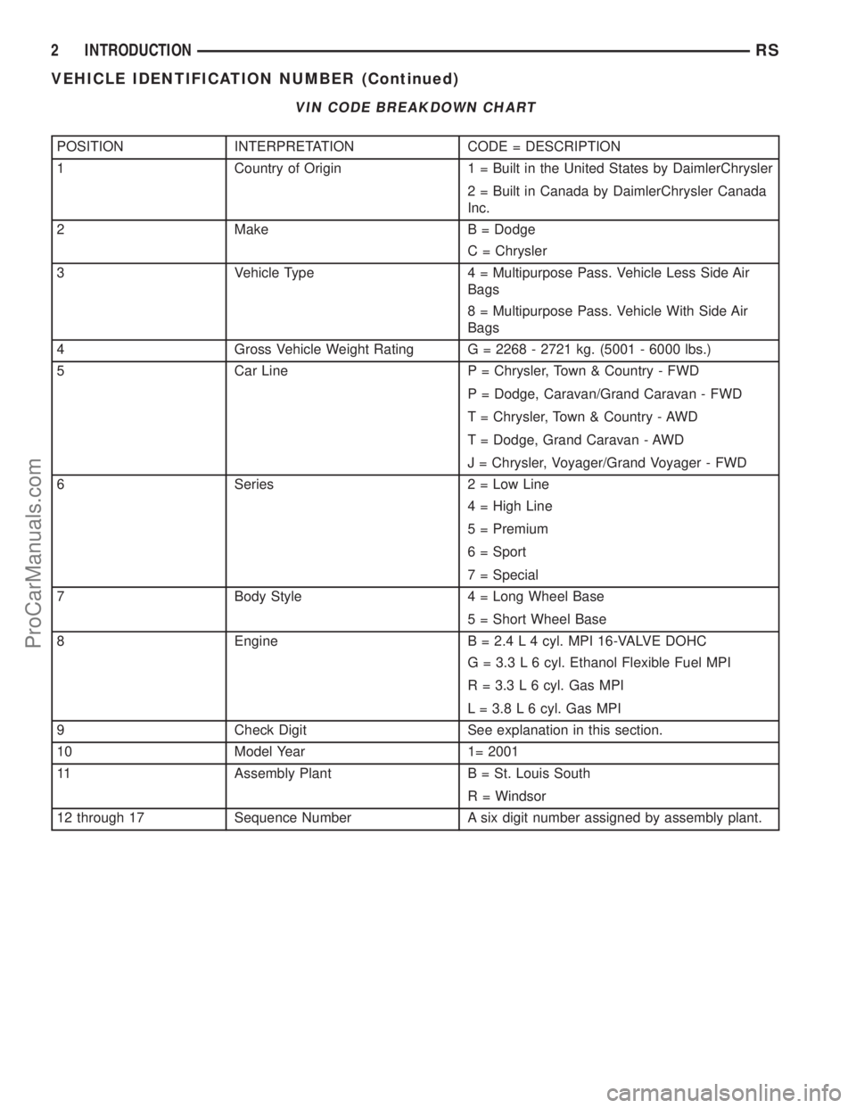
VIN CODE BREAKDOWN CHART
POSITION INTERPRETATION CODE = DESCRIPTION
1 Country of Origin 1 = Built in the United States by DaimlerChrysler
2 = Built in Canada by DaimlerChrysler Canada
Inc.
2 Make B = Dodge
C = Chrysler
3 Vehicle Type 4 = Multipurpose Pass. Vehicle Less Side Air
Bags
8 = Multipurpose Pass. Vehicle With Side Air
Bags
4 Gross Vehicle Weight Rating G = 2268 - 2721 kg. (5001 - 6000 lbs.)
5 Car Line P = Chrysler, Town & Country - FWD
P = Dodge, Caravan/Grand Caravan - FWD
T = Chrysler, Town & Country - AWD
T = Dodge, Grand Caravan - AWD
J = Chrysler, Voyager/Grand Voyager - FWD
6 Series 2 = Low Line
4 = High Line
5 = Premium
6 = Sport
7 = Special
7 Body Style 4 = Long Wheel Base
5 = Short Wheel Base
8 Engine B = 2.4 L 4 cyl. MPI 16-VALVE DOHC
G = 3.3 L 6 cyl. Ethanol Flexible Fuel MPI
R = 3.3 L 6 cyl. Gas MPI
L = 3.8 L 6 cyl. Gas MPI
9 Check Digit See explanation in this section.
10 Model Year 1= 2001
11 Assembly Plant B = St. Louis South
R = Windsor
12 through 17 Sequence Number A six digit number assigned by assembly plant.
2 INTRODUCTIONRS
VEHICLE IDENTIFICATION NUMBER (Continued)
ProCarManuals.com
Page 20 of 2321
VEHICLE IDENTIFICATION
NUMBER
DESCRIPTION
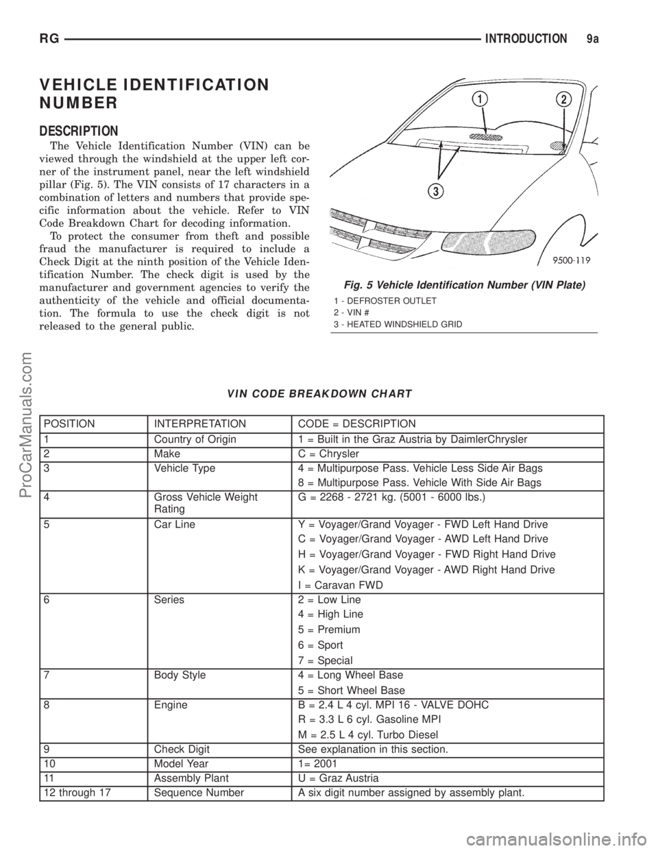
The Vehicle Identification Number (VIN) can be
viewed through the windshield at the upper left cor-
ner of the instrument panel, near the left windshield
pillar (Fig. 5). The VIN consists of 17 characters in a
combination of letters and numbers that provide spe-
cific information about the vehicle. Refer to VIN
Code Breakdown Chart for decoding information.
To protect the consumer from theft and possible
fraud the manufacturer is required to include a
Check Digit at the ninth position of the Vehicle Iden-
tification Number. The check digit is used by the
manufacturer and government agencies to verify the
authenticity of the vehicle and official documenta-
tion. The formula to use the check digit is not
released to the general public.
VIN CODE BREAKDOWN CHART
POSITION INTERPRETATION CODE = DESCRIPTION
1 Country of Origin 1 = Built in the Graz Austria by DaimlerChrysler
2 Make C = Chrysler
3 Vehicle Type 4 = Multipurpose Pass. Vehicle Less Side Air Bags
8 = Multipurpose Pass. Vehicle With Side Air Bags
4 Gross Vehicle Weight
RatingG = 2268 - 2721 kg. (5001 - 6000 lbs.)
5 Car Line Y = Voyager/Grand Voyager - FWD Left Hand Drive
C = Voyager/Grand Voyager - AWD Left Hand Drive
H = Voyager/Grand Voyager - FWD Right Hand Drive
K = Voyager/Grand Voyager - AWD Right Hand Drive
I = Caravan FWD
6 Series 2 = Low Line
4 = High Line
5 = Premium
6 = Sport
7 = Special
7 Body Style 4 = Long Wheel Base
5 = Short Wheel Base
8 Engine B = 2.4 L 4 cyl. MPI 16 - VALVE DOHC
R = 3.3 L 6 cyl. Gasoline MPI
M = 2.5 L 4 cyl. Turbo Diesel
9 Check Digit See explanation in this section.
10 Model Year 1= 2001
11 Assembly Plant U = Graz Austria
12 through 17 Sequence Number A six digit number assigned by assembly plant.
Fig. 5 Vehicle Identification Number (VIN Plate)
1 - DEFROSTER OUTLET
2 - VIN #
3 - HEATED WINDSHIELD GRID
RGINTRODUCTION9a
ProCarManuals.com
Page 21 of 2321
VEHICLE SAFETY
CERTIFICATION LABEL
DESCRIPTION
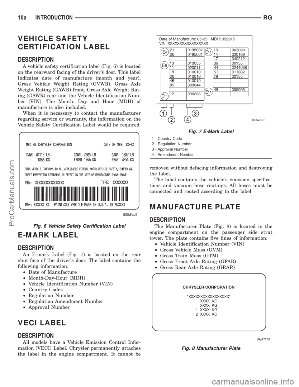
A vehicle safety certification label (Fig. 6) is located
on the rearward facing of the driver's door. This label
indicates date of manufacture (month and year),
Gross Vehicle Weight Rating (GVWR), Gross Axle
Weight Rating (GAWR) front, Gross Axle Weight Rat-
ing (GAWR) rear and the Vehicle Identification Num-
ber (VIN). The Month, Day and Hour (MDH) of
manufacture is also included.
When it is necessary to contact the manufacturer
regarding service or warranty, the information on the
Vehicle Safety Certification Label would be required.
E-MARK LABEL
DESCRIPTION
An E-mark Label (Fig. 7) is located on the rear
shut face of the driver's door. The label contains the
following information:
²Date of Manufacture
²Month-Day-Hour (MDH)
²Vehicle Identification Number (VIN)
²Country Codes
²Regulation Number
²Regulation Amendment Number
²Approval Number
VECI LABEL
DESCRIPTION
All models have a Vehicle Emission Control Infor-
mation (VECI) Label. Chrysler permanently attaches
the label in the engine compartment. It cannot beremoved without defacing information and destroying
the label.
The label contains the vehicle's emission specifica-
tions and vacuum hose routings. All hoses must be
connected and routed according to the label.
MANUFACTURE PLATE
DESCRIPTION
The Manufacturer Plate (Fig. 8) is located in the
engine compartment on the passenger side strut
tower. The plate contains five lines of information:
²Vehicle Identification Number (VIN)
²Gross Vehicle Mass (GVM)
²Gross Train Mass (GTM)
²Gross Front Axle Rating (GFAR)
²Gross Rear Axle Rating (GRAR)Fig. 6 Vehicle Safety Certification Label
Fig. 7 E-Mark Label
1 - Country Code
2 - Regulation Number
3 - Approval Number
4 - Amendment Number
Fig. 8 Manufacturer Plate
10a INTRODUCTIONRG
ProCarManuals.com
Page 38 of 2321
transmission in NEUTRAL and turn the ignition
OFF.
(3) On disabled vehicle, place gear selector in park
or neutral and set park brake. Turn off all accesso-
ries.
(4) Connect jumper cables to booster battery. RED
clamp to positive terminal (+). BLACK clamp to neg-
ative terminal (-). DO NOT allow clamps at opposite
end of cables to touch, electrical arc will result.
Review all warnings in this procedure.
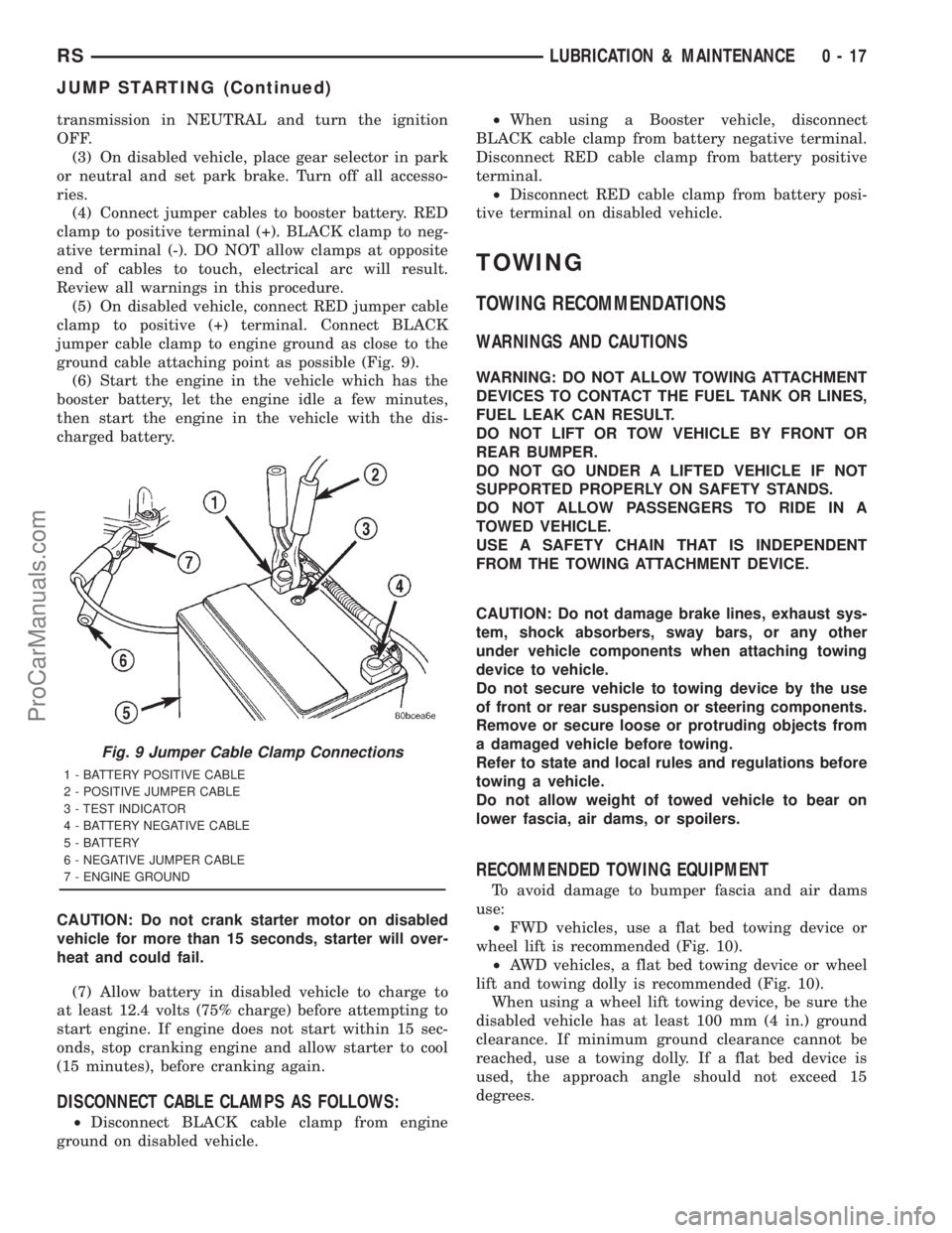
(5) On disabled vehicle, connect RED jumper cable
clamp to positive (+) terminal. Connect BLACK
jumper cable clamp to engine ground as close to the
ground cable attaching point as possible (Fig. 9).
(6) Start the engine in the vehicle which has the
booster battery, let the engine idle a few minutes,
then start the engine in the vehicle with the dis-
charged battery.
CAUTION: Do not crank starter motor on disabled
vehicle for more than 15 seconds, starter will over-
heat and could fail.
(7) Allow battery in disabled vehicle to charge to
at least 12.4 volts (75% charge) before attempting to
start engine. If engine does not start within 15 sec-
onds, stop cranking engine and allow starter to cool
(15 minutes), before cranking again.
DISCONNECT CABLE CLAMPS AS FOLLOWS:
²Disconnect BLACK cable clamp from engine
ground on disabled vehicle.²When using a Booster vehicle, disconnect
BLACK cable clamp from battery negative terminal.
Disconnect RED cable clamp from battery positive
terminal.
²Disconnect RED cable clamp from battery posi-
tive terminal on disabled vehicle.
TOWING
TOWING RECOMMENDATIONS
WARNINGS AND CAUTIONS
WARNING: DO NOT ALLOW TOWING ATTACHMENT
DEVICES TO CONTACT THE FUEL TANK OR LINES,
FUEL LEAK CAN RESULT.
DO NOT LIFT OR TOW VEHICLE BY FRONT OR
REAR BUMPER.
DO NOT GO UNDER A LIFTED VEHICLE IF NOT
SUPPORTED PROPERLY ON SAFETY STANDS.
DO NOT ALLOW PASSENGERS TO RIDE IN A
TOWED VEHICLE.
USE A SAFETY CHAIN THAT IS INDEPENDENT
FROM THE TOWING ATTACHMENT DEVICE.
CAUTION: Do not damage brake lines, exhaust sys-
tem, shock absorbers, sway bars, or any other
under vehicle components when attaching towing
device to vehicle.
Do not secure vehicle to towing device by the use
of front or rear suspension or steering components.
Remove or secure loose or protruding objects from
a damaged vehicle before towing.
Refer to state and local rules and regulations before
towing a vehicle.
Do not allow weight of towed vehicle to bear on
lower fascia, air dams, or spoilers.
RECOMMENDED TOWING EQUIPMENT
To avoid damage to bumper fascia and air dams
use:
²FWD vehicles, use a flat bed towing device or
wheel lift is recommended (Fig. 10).
²AWD vehicles, a flat bed towing device or wheel
lift and towing dolly is recommended (Fig. 10).
When using a wheel lift towing device, be sure the
disabled vehicle has at least 100 mm (4 in.) ground
clearance. If minimum ground clearance cannot be
reached, use a towing dolly. If a flat bed device is
used, the approach angle should not exceed 15
degrees.
Fig. 9 Jumper Cable Clamp Connections
1 - BATTERY POSITIVE CABLE
2 - POSITIVE JUMPER CABLE
3 - TEST INDICATOR
4 - BATTERY NEGATIVE CABLE
5 - BATTERY
6 - NEGATIVE JUMPER CABLE
7 - ENGINE GROUND
RSLUBRICATION & MAINTENANCE0-17
JUMP STARTING (Continued)
ProCarManuals.com
Page 47 of 2321
JUMP STARTING
STANDARD PROCEDURE - JUMP STARTING
(1) Raise hood on disabled vehicle and visually
inspect engine compartment for:
²Battery cable clamp condition, clean if necessary.
²Frozen battery.
²Yellow or bright color test indicator, if equipped.
²Low battery fluid level.
²Generator drive belt condition and tension.
²Fuel fumes or leakage, correct if necessary.
CAUTION: If the cause of starting problem on dis-
abled vehicle is severe, damage to booster vehicle
charging system can result.
(2) When using another vehicle as a booster
source, park the booster vehicle within cable reach.
Turn off all accessories, set the parking brake, place
the automatic transmission in PARK or the manual
transmission in NEUTRAL and turn the ignition
OFF.
(3)
On disabled vehicle, place gear selector in park
or neutral and set park brake. Turn off all accessories.
(4) Connect jumper cables to booster battery. RED
clamp to positive terminal (+). BLACK clamp to neg-
ative terminal (-). DO NOT allow clamps at opposite
end of cables to touch, electrical arc will result.
Review all warnings in this procedure.
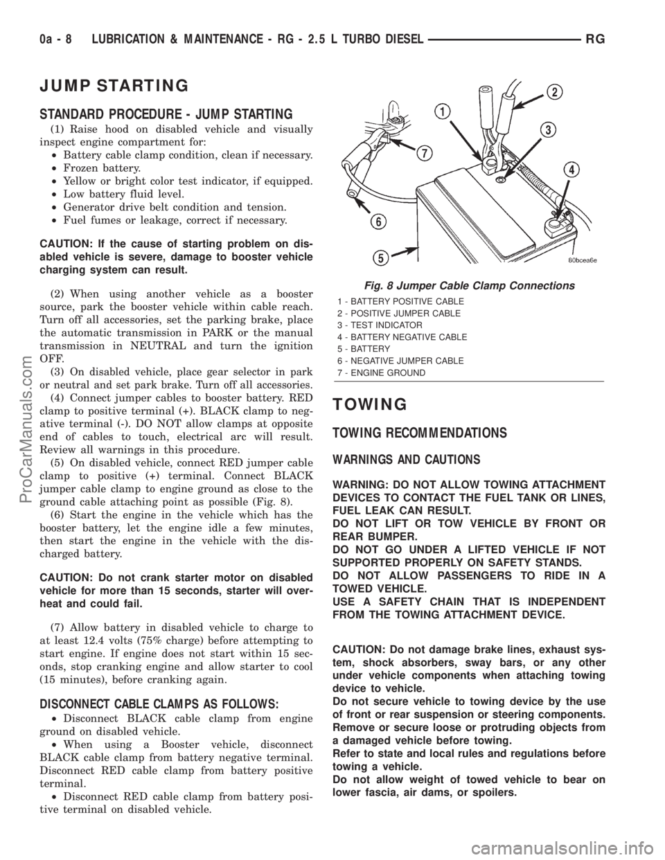
(5) On disabled vehicle, connect RED jumper cable
clamp to positive (+) terminal. Connect BLACK
jumper cable clamp to engine ground as close to the
ground cable attaching point as possible (Fig. 8).
(6) Start the engine in the vehicle which has the
booster battery, let the engine idle a few minutes,
then start the engine in the vehicle with the dis-
charged battery.
CAUTION: Do not crank starter motor on disabled
vehicle for more than 15 seconds, starter will over-
heat and could fail.
(7) Allow battery in disabled vehicle to charge to
at least 12.4 volts (75% charge) before attempting to
start engine. If engine does not start within 15 sec-
onds, stop cranking engine and allow starter to cool
(15 minutes), before cranking again.
DISCONNECT CABLE CLAMPS AS FOLLOWS:
²Disconnect BLACK cable clamp from engine
ground on disabled vehicle.
²When using a Booster vehicle, disconnect
BLACK cable clamp from battery negative terminal.
Disconnect RED cable clamp from battery positive
terminal.
²Disconnect RED cable clamp from battery posi-
tive terminal on disabled vehicle.
TOWING
TOWING RECOMMENDATIONS
WARNINGS AND CAUTIONS
WARNING: DO NOT ALLOW TOWING ATTACHMENT
DEVICES TO CONTACT THE FUEL TANK OR LINES,
FUEL LEAK CAN RESULT.
DO NOT LIFT OR TOW VEHICLE BY FRONT OR
REAR BUMPER.
DO NOT GO UNDER A LIFTED VEHICLE IF NOT
SUPPORTED PROPERLY ON SAFETY STANDS.
DO NOT ALLOW PASSENGERS TO RIDE IN A
TOWED VEHICLE.
USE A SAFETY CHAIN THAT IS INDEPENDENT
FROM THE TOWING ATTACHMENT DEVICE.
CAUTION: Do not damage brake lines, exhaust sys-
tem, shock absorbers, sway bars, or any other
under vehicle components when attaching towing
device to vehicle.
Do not secure vehicle to towing device by the use
of front or rear suspension or steering components.
Remove or secure loose or protruding objects from
a damaged vehicle before towing.
Refer to state and local rules and regulations before
towing a vehicle.
Do not allow weight of towed vehicle to bear on
lower fascia, air dams, or spoilers.
Fig. 8 Jumper Cable Clamp Connections
1 - BATTERY POSITIVE CABLE
2 - POSITIVE JUMPER CABLE
3 - TEST INDICATOR
4 - BATTERY NEGATIVE CABLE
5 - BATTERY
6 - NEGATIVE JUMPER CABLE
7 - ENGINE GROUND
0a - 8 LUBRICATION & MAINTENANCE - RG - 2.5 L TURBO DIESELRG
ProCarManuals.com
Page 60 of 2321
OPERATION
The ball joint is a pivotal joint on the lower control
arm that allows the knuckle to move up and down,
and turn with ease.
DIAGNOSIS AND TESTING - LOWER BALL
JOINT
With the weight of the vehicle resting on the road
wheels, grasp the special fitting cap on the bottom of
the ball joint and with no mechanical assistance or
added force, attempt to rotate the grease fitting.
If the ball joint is worn, the grease fitting will
rotate easily. If movement is noted, replacement of
the ball joint is recommended.
LOWER BALL JOINT SEAL
BOOT
REMOVAL - BALL JOINT SEAL BOOT
(1) Remove steering knuckle from vehicle. (Refer
to 2 - SUSPENSION/FRONT/KNUCKLE -
REMOVAL)
(2) Using a screw driver or other suitable tool, pry
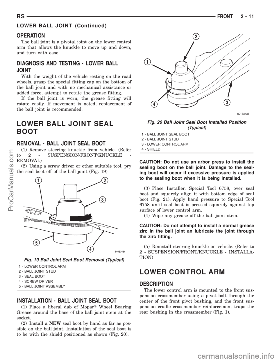
the seal boot off of the ball joint (Fig. 19)
INSTALLATION - BALL JOINT SEAL BOOT
(1) Place a liberal dab of MopartWheel Bearing
Grease around the base of the ball joint stem at the
socket.
(2) Install aNEWseal boot by hand as far as pos-
sible on the ball joint. Installation of the seal boot is
to be with the shield positioned as shown (Fig. 20).CAUTION: Do not use an arbor press to install the
sealing boot on the ball joint. Damage to the seal-
ing boot will occur if excessive pressure is applied
to the sealing boot when it is being installed.
(3) Place Installer, Special Tool 6758, over seal
boot and squarely align it with bottom edge of seal
boot (Fig. 21). Apply hand pressure to Special Tool
6758 until seal boot is pressed squarely against top
surface of lower control arm.
(4) Wipe any grease off the ball joint stem.
CAUTION: Do not attempt to install a normal grease
zirc in the ball joint an lubricate the joint through
the zirc fitting.
(5) Reinstall steering knuckle on vehicle. (Refer to
2 - SUSPENSION/FRONT/KNUCKLE - INSTALLA-
TION)
LOWER CONTROL ARM
DESCRIPTION
The lower control arm is mounted to the front sus-
pension crossmember using a pivot bolt through the
center of the front pivot bushing, and the front sus-
pension cradle crossmember reinforcement traps the
rear bushing in the crossmember (Fig. 1).
Fig. 19 Ball Joint Seal Boot Removal (Typical)
1 - LOWER CONTROL ARM
2 - BALL JOINT STUD
3 - SEAL BOOT
4 - SCREW DRIVER
5 - BALL JOINT ASSEMBLY
Fig. 20 Ball Joint Seal Boot Installed Position
(Typical)
1 - BALL JOINT SEAL BOOT
2 - BALL JOINT STUD
3 - LOWER CONTROL ARM
4 - SHIELD
RSFRONT2-11
LOWER BALL JOINT (Continued)
ProCarManuals.com
Page 64 of 2321
reached. This will properly space bushing on the
stem in relation to the flange.
(6) Back off the forcing screw and remove tool.
(7) Install lower control arm on vehicle. (Refer to 2
- SUSPENSION/FRONT/LOWER CONTROL ARM -
INSTALLATION)
INSTALLATION - LOWER CONTROL ARM
(1) Position lower control arm assembly into front
suspension cradle crossmember guiding bushings into
mounting position (Fig. 23).(2) Install NEW pivot bolt attaching front bushing
of lower control arm to front suspension cradle cross-
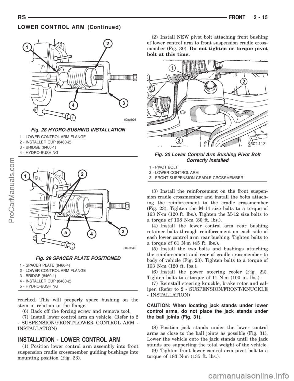
member (Fig. 30).Do not tighten or torque pivot
bolt at this time.
(3) Install the reinforcement on the front suspen-
sion cradle crossmember and install the bolts attach-
ing the reinforcement to the cradle crossmember
(Fig. 23). Tighten the M-14 size bolts to a torque of
163 N´m (120 ft. lbs.). Tighten the M-12 size bolts to
a torque of 108 N´m (80 ft. lbs.).
(4) Install the lower control arm rear bushing
retainer bolts through reinforcement on each side of
each lower control arm rear bushing. Tighten bolts to
a torque of 61 N´m (45 ft. lbs.).
(5) Install the two bolts and bushings attaching
the reinforcement and rear of cradle crossmember to
body of vehicle (Fig. 23). Tighten bolts to a torque of
163 N´m (120 ft. lbs.).
(6) Install the power steering cooler (Fig. 22).
Tighten bolts to a torque of 11 N´m (100 in. lbs.).
(7) Reinstall steering knuckle, brake rotor and cal-
iper. (Refer to 2 - SUSPENSION/FRONT/KNUCKLE
- INSTALLATION)
CAUTION: When locating jack stands under lower
control arms, do not place the jack stands under
the ball joints (Fig. 31).
(8) Position jack stands under the lower control
arms as close to the ball joints as possible (Fig. 31).
Lower the vehicle onto the jack stands until the jack
stands are supporting the total weight of the vehicle.
(9) Tighten front lower control arm pivot bolt to a
torque of 183 N´m (135 ft. lbs.).
Fig. 28 HYDRO-BUSHING INSTALLATION
1 - LOWER CONTROL ARM FLANGE
2 - INSTALLER CUP (8460-2)
3 - BRIDGE (8460-1)
4 - HYDRO-BUSHING
Fig. 29 SPACER PLATE POSITIONED
1 - SPACER PLATE (8460-4)
2 - LOWER CONTROL ARM FLANGE
3 - BRIDGE (8460-1)
4 - INSTALLER CUP (8460-2)
5 - HYDRO-BUSHING
Fig. 30 Lower Control Arm Bushing Pivot Bolt
Correctly Installed
1 - PIVOT BOLT
2 - LOWER CONTROL ARM
3 - FRONT SUSPENSION CRADLE CROSSMEMBER
RSFRONT2-15
LOWER CONTROL ARM (Continued)
ProCarManuals.com