2001 DODGE TOWN AND COUNTRY weight
[x] Cancel search: weightPage 485 of 2321
HEADLAMP UNIT
REMOVAL
(1) Disconnect and isolate the battery negative
cable.
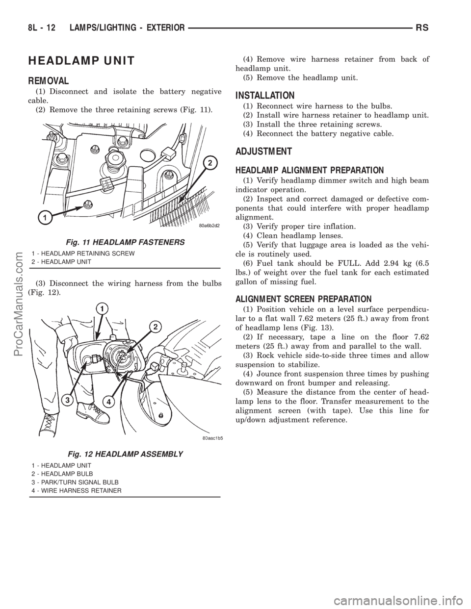
(2) Remove the three retaining screws (Fig. 11).
(3) Disconnect the wiring harness from the bulbs
(Fig. 12).(4) Remove wire harness retainer from back of
headlamp unit.
(5) Remove the headlamp unit.INSTALLATION
(1) Reconnect wire harness to the bulbs.
(2) Install wire harness retainer to headlamp unit.
(3) Install the three retaining screws.
(4) Reconnect the battery negative cable.
ADJUSTMENT
HEADLAMP ALIGNMENT PREPARATION
(1) Verify headlamp dimmer switch and high beam
indicator operation.
(2) Inspect and correct damaged or defective com-
ponents that could interfere with proper headlamp
alignment.
(3) Verify proper tire inflation.
(4) Clean headlamp lenses.
(5) Verify that luggage area is loaded as the vehi-
cle is routinely used.
(6) Fuel tank should be FULL. Add 2.94 kg (6.5
lbs.) of weight over the fuel tank for each estimated
gallon of missing fuel.
ALIGNMENT SCREEN PREPARATION
(1) Position vehicle on a level surface perpendicu-
lar to a flat wall 7.62 meters (25 ft.) away from front
of headlamp lens (Fig. 13).
(2) If necessary, tape a line on the floor 7.62
meters (25 ft.) away from and parallel to the wall.
(3) Rock vehicle side-to-side three times and allow
suspension to stabilize.
(4) Jounce front suspension three times by pushing
downward on front bumper and releasing.
(5) Measure the distance from the center of head-
lamp lens to the floor. Transfer measurement to the
alignment screen (with tape). Use this line for
up/down adjustment reference.
Fig. 11 HEADLAMP FASTENERS
1 - HEADLAMP RETAINING SCREW
2 - HEADLAMP UNIT
Fig. 12 HEADLAMP ASSEMBLY
1 - HEADLAMP UNIT
2 - HEADLAMP BULB
3 - PARK/TURN SIGNAL BULB
4 - WIRE HARNESS RETAINER
8L - 12 LAMPS/LIGHTING - EXTERIORRS
ProCarManuals.com
Page 499 of 2321

HEADLAMP UNIT
ADJUSTMENT
HEADLAMP ALIGNMENT PREPARATION
(1) Verify headlamp dimmer switch and high beam
indicator operation.
(2) Verify that the headlamp leveling switch is in
the ª0º position.
(3) Inspect and correct damaged or defective com-
ponents that could interfere with proper headlamp
alignment.
(4) Verify proper tire inflation.
(5) Clean headlamp lenses.
(6) Verify that luggage area is loaded as the vehi-
cle is routinely used.
(7) Fuel tank should be FULL. Add 2.94 kg (6.5
lbs.) of weight over the fuel tank for each estimated
gallon of missing fuel.
ALIGNMENT SCREEN PREPARATION
(1) Position vehicle on a level surface perpendicu-
lar to a flat wall 10 meters (32.8 ft.) away from front
of headlamp lens (Fig. 8).
(2) If necessary, tape a line on the floor 10 meters
(32.8 ft.) away from and parallel to the wall.
(3) Rock vehicle side-to-side three times and allow
suspension to stabilize.
(4) Jounce front suspension three times by pushing
downward on front bumper and releasing.
(5) Measure the distance from the center of head-
lamp lens to the floor. Transfer measurement to the
alignment screen (with tape). Use this line for
up/down adjustment reference.
HEADLAMP ADJUSTMENT
The low beam headlamp will project on the screen
upper edge of the beam (cut-off) at the horizontal
lamp centerline 20 mm (0.75 in.). The high beam
pattern should be correct when the low beams are
aligned properly (Fig. 9). To adjust headlamp align-
ment, rotate adjustment screws to achieve the speci-
fied low beam cut-off location.
Fig. 8 HEADLAMP ALIGNMENT SCREEN
1 - CENTER OF VEHICLE
2 - CENTER OF HEADLAMPS
3 - 15É CUT-OFF LINE
4 - FRONT OF HEADLAMP5 - 10 METERS (32.8 FT.)
6 - HORIZONTAL CUT-OFF LINE
7 - 110 mm (4.3 in.)
8La - 6 LAMPSRG
ProCarManuals.com
Page 547 of 2321
(4) Disconnect the flex drive assembly from the
lower drive unit. Expand the flex drive collar until
the lower drive unit can be pulled straight off.
(5) Remove the lower drive unit from the vehicle.
INSTALLATION
(1)Position the lower drive unit near the lower hinge.
(2) Connect the flex drive assembly on the lower
drive unit. Push the flex drive collar straight on until
the it snaps in place (Fig. 12).
(3) Install the lower drive unit retaining fasteners
(Fig. 12). Torque the larger allen headed center stud
to 9 N´m (80 in. lbs.). Torque the smaller screw to 3
N´m (28 in. lbs.).
(4) Install the lower drive unit cover and retaining
screws (Fig. 11).
(5) Connect the negative battery cable.
LOWER DRIVE UNIT TRACK &
RACK
DESCRIPTION
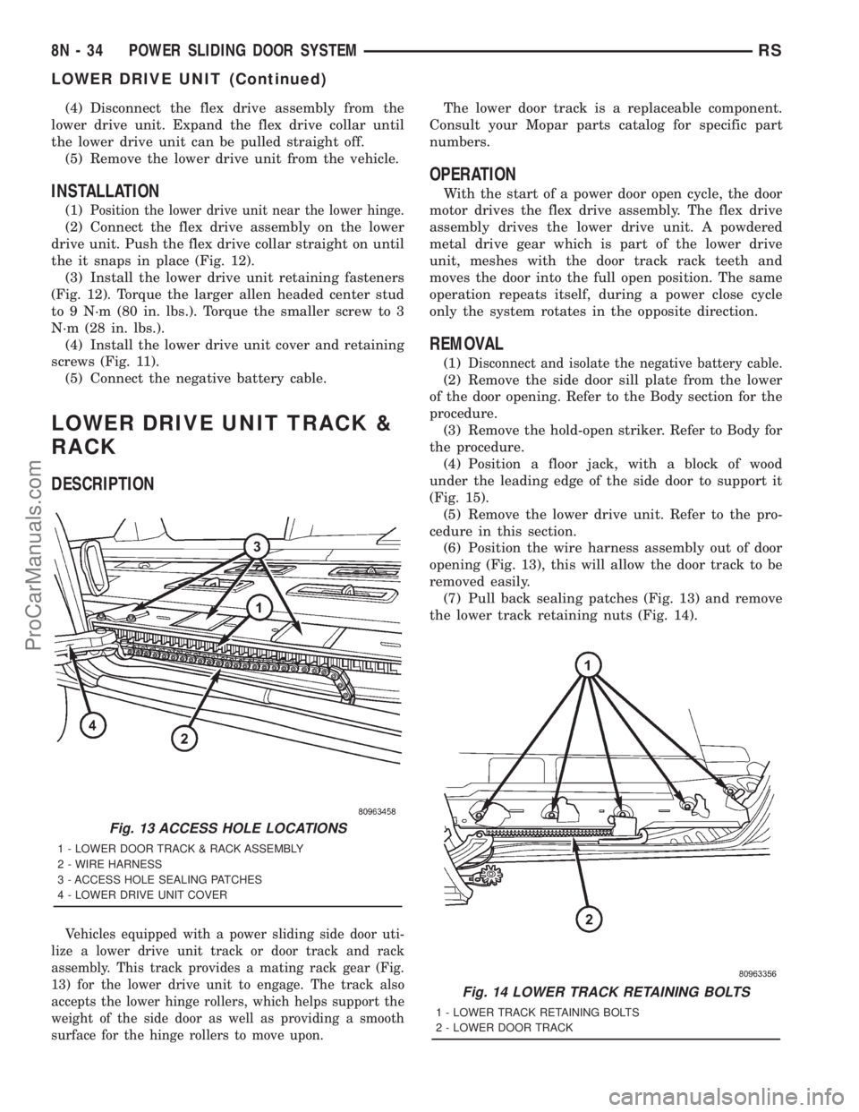
Vehicles equipped with a power sliding side door uti-
lize a lower drive unit track or door track and rack
assembly. This track provides a mating rack gear (Fig.
13) for the lower drive unit to engage. The track also
accepts the lower hinge rollers, which helps support the
weight of the side door as well as providing a smooth
surface for the hinge rollers to move upon.
The lower door track is a replaceable component.
Consult your Mopar parts catalog for specific part
numbers.
OPERATION
With the start of a power door open cycle, the door
motor drives the flex drive assembly. The flex drive
assembly drives the lower drive unit. A powdered
metal drive gear which is part of the lower drive
unit, meshes with the door track rack teeth and
moves the door into the full open position. The same
operation repeats itself, during a power close cycle
only the system rotates in the opposite direction.
REMOVAL
(1)Disconnect and isolate the negative battery cable.
(2) Remove the side door sill plate from the lower
of the door opening. Refer to the Body section for the
procedure.
(3) Remove the hold-open striker. Refer to Body for
the procedure.
(4) Position a floor jack, with a block of wood
under the leading edge of the side door to support it
(Fig. 15).
(5) Remove the lower drive unit. Refer to the pro-
cedure in this section.
(6) Position the wire harness assembly out of door
opening (Fig. 13), this will allow the door track to be
removed easily.
(7) Pull back sealing patches (Fig. 13) and remove
the lower track retaining nuts (Fig. 14).
Fig. 13 ACCESS HOLE LOCATIONS
1 - LOWER DOOR TRACK & RACK ASSEMBLY
2 - WIRE HARNESS
3 - ACCESS HOLE SEALING PATCHES
4 - LOWER DRIVE UNIT COVER
Fig. 14 LOWER TRACK RETAINING BOLTS
1 - LOWER TRACK RETAINING BOLTS
2 - LOWER DOOR TRACK
8N - 34 POWER SLIDING DOOR SYSTEMRS
LOWER DRIVE UNIT (Continued)
ProCarManuals.com
Page 1170 of 2321
(24) Remove rear engine mount bracket. (Refer to
9 - ENGINE/ENGINE MOUNTING/REAR MOUNT -
REMOVAL)
(25) Mark flex plate to torque converter and
remove torque converter bolts.
(26) Pinch-off power steering supply hose at pump.
Remove hose from pump.
(27) Remove and set aside the power steering
pump and bracket. Do not disconnect pressure line.
(28) Lower vehicle.(29) Remove A/C lines at compressor and cap open-
ings.
(30) Remove engine ground straps (strap at engine
right mount and at starter).
(31) Raise vehicle enough to allow engine dolly
Special Tool 6135, cradle Special Tool 6710 with
Posts Special Tool 6848 to be installed under vehicle
(Fig. 8).
(32) Loosen cradle posts to allow movement for
proper positioning. Locate two rear posts (right side
of engine) into the holes on the engine bedplate.
Locate the two front posts (left side of engine) on the
oil pan rails (Fig. 8). Lower vehicle and position cra-
dle mounts until the engine is resting on mounts.
Tighten mounts to cradle frame. This will keep
mounts from moving when removing or installing
engine and transmission.
(33) Install safety straps around the engine to cra-
dle. Tighten straps and lock.
(34) Lower vehicle so the weight ofONLY THE
ENGINE AND TRANSMISSIONare on the cradle.
(35) Remove engine and transmission mount bolts.
(36) Raise vehicle slowly. It may be necessary to
move the engine/transmission assembly on the cradle
to allow for removal around the body.
INSTALLATION - ENGINE ASSEMBLY
(1) Position engine and transmission assembly
under vehicle and slowly lower the vehicle over the
engine and transmission.
(2) Align engine and transmission mounts to
attaching points. Install mounting bolts at the right
(Fig. 9) and left mounts (Fig. 10).
(3) Remove safety straps.
(4) Slowly raise vehicle enough to remove the
engine dolly and cradle Special Tools 6135 and 6710.
(5) Install rear mount bracket and rear mount
through bolt. (Refer to 9 - ENGINE/ENGINE
MOUNTING/REAR MOUNT - INSTALLATION)
(6) Install the flex plate to torque converter bolts.
(7) Install structural collar. (Refer to 9 - ENGINE/
ENGINE BLOCK/STRUCTURAL COVER - INSTAL-
LATION)
(8) Install front mount bracket and front mount
through bolt. (Refer to 9 - ENGINE/ENGINE
MOUNTING/FRONT MOUNT - INSTALLATION)
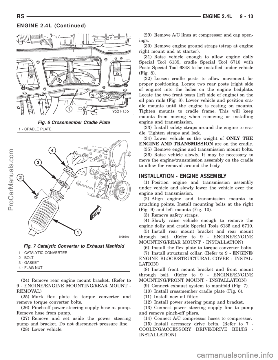
(9) Connect exhaust system to manifold (Fig. 7).
(10) Install crossmember cradle plate (Fig. 6).
(11) Install new oil filter.
(12) Install power steering pump and bracket.
(13) Connect power steering supply line to pump
and remove pinch-off pliers.
(14) Connect A/C compressor hoses to compressor.
(15) Install accessory drive belts. (Refer to 7 -
COOLING/ACCESSORY DRIVE/DRIVE BELTS -
INSTALLATION)
Fig. 6 Crossmember Cradle Plate
1 - CRADLE PLATE
Fig. 7 Catalytic Converter to Exhaust Manifold
1 - CATALYTIC CONVERTER
2 - BOLT
3 - GASKET
4 - FLAG NUT
RSENGINE 2.4L9-13
ENGINE 2.4L (Continued)
ProCarManuals.com
Page 1173 of 2321
SPECIFICATIONS
SPECIFICATIONS - 2.4L ENGINE
DESCRIPTION SPECIFICATION
General Specification
Type In-Line OHV, DOHC
Number of Cylinders 4
Displacement 2.4 Liters
(148 cu. in.)
Bore 87.5 mm
(3.445 in.)
Stroke 101.0 mm
(3.976 in.)
Compression Ratio 9.4:1
Firing Order 1-3-4-2
Compression Pressure 690 kPa (Minimum)
(100 psi Minimum)
Max. Variation Between
Cylinders25%
Cylinder Block
Cylinder Bore Diameter 87.4924±87.5076 mm
(3.4446±3.4452 in.)
Out-of-Round (Max.) 0.051 mm
(0.002 in.)
Taper (Max.) 0.051 mm
(0.002 in.)
Pistons
Piston Diameter 87.463±87.481 mm
(3.4434±3.4441 in.)
Clearance @ 14 mm
(9/16 in.) from bottom of
skirt0.024±0.057 mm
(0.0009±0.0022 in.)
Weight 346±356 grams
(12.20±12.56 oz.)
Land Clearance
(Diametrical)0.614±0.664 mm
(0.024±0.026 in.)
Piston Length 66.25 mm
(2.608 in.)
Piston Ring Groove
Depth No. 14.640±4.784 mm
(0.182±0.188 in.)
Piston Ring Groove
Depth No. 24.575±4.719 mm
(0.180±0.185 in.)
DESCRIPTION SPECIFICATION
Piston Ring Groove
Depth No. 34.097±4.236 mm
(0.161±0.166 in.)
Piston Pins
Clearance in Piston 0.005±0.018 mm
(0.0002±0.0008 in.)
Clearance in Connecting
RodInterference
Diameter 21.998±22.003 mm
(0.8660±0.8662 in.)
End Play None
Length 72.75±73.25 mm
(2.864±2.883 in.)
Piston Rings
Ring GapÐTop
Compression Ring0.25±0.51 mm
(0.0098±0.020 in.)
Wear Limit 0.8 mm
(0.031 in.)
Ring GapÐ2nd
Compression Ring0.23±0.48 mm
(0.009±0.018 in.)
Wear Limit 0.8 mm
(0.031 in.)
Ring GapÐOil Control
Steel Rails0.25±0.64 mm
(0.0098±0.025 in.)
Wear Limit 1.0 mm
(0.039 in.)
Ring Side ClearanceÐ
Compression Rings0.030±0.080 mm
(0.0011±0.0031 in.)
Wear Limit 0.10 mm
(0.004 in.)
Ring Side ClearanceÐOil
Ring Pack0.012±0.178 mm
(0.0004±0.0070 in.)
Ring WidthÐ
Compression Rings1.47±1.50 mm
(0.057±0.059 in.)
Ring WidthÐOil Ring
Pack2.72±2.88 mm
(0.107±0.1133 in.)
Connecting Rod
Bearing Clearance 0.025±0.071 mm
(0.0009±0.0027 in.)
Wear Limit 0.075 mm
(0.003 in.)
Bore DiameterÐPiston
Pin20.96±20.98 mm
(0.8252±0.8260 in.)
9 - 16 ENGINE 2.4LRS
ProCarManuals.com
Page 1174 of 2321
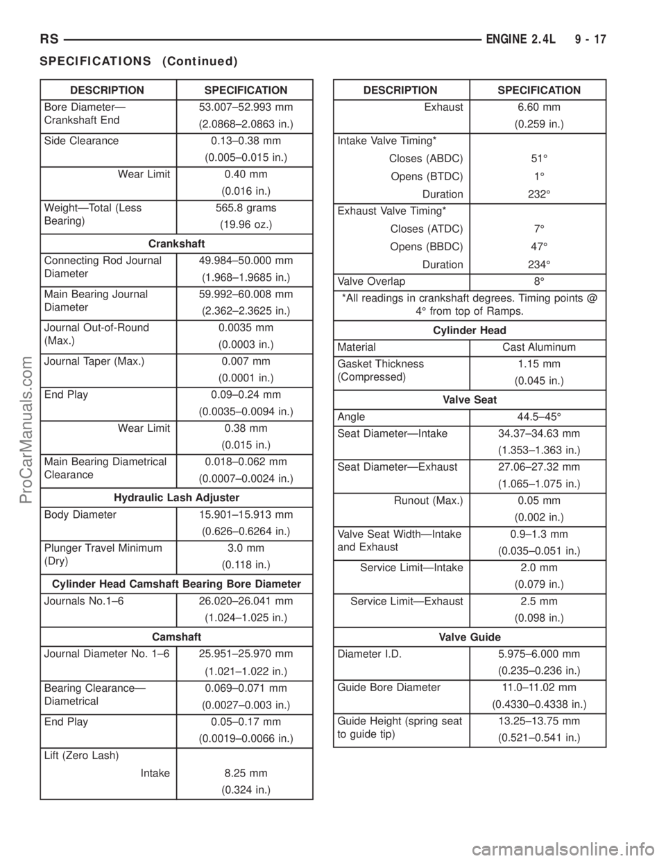
DESCRIPTION SPECIFICATION
Bore DiameterÐ
Crankshaft End53.007±52.993 mm
(2.0868±2.0863 in.)
Side Clearance 0.13±0.38 mm
(0.005±0.015 in.)
Wear Limit 0.40 mm
(0.016 in.)
WeightÐTotal (Less
Bearing)565.8 grams
(19.96 oz.)
Crankshaft
Connecting Rod Journal
Diameter49.984±50.000 mm
(1.968±1.9685 in.)
Main Bearing Journal
Diameter59.992±60.008 mm
(2.362±2.3625 in.)
Journal Out-of-Round
(Max.)0.0035 mm
(0.0003 in.)
Journal Taper (Max.) 0.007 mm
(0.0001 in.)
End Play 0.09±0.24 mm
(0.0035±0.0094 in.)
Wear Limit 0.38 mm
(0.015 in.)
Main Bearing Diametrical
Clearance0.018±0.062 mm
(0.0007±0.0024 in.)
Hydraulic Lash Adjuster
Body Diameter 15.901±15.913 mm
(0.626±0.6264 in.)
Plunger Travel Minimum
(Dry)3.0 mm
(0.118 in.)
Cylinder Head Camshaft Bearing Bore Diameter
Journals No.1±6 26.020±26.041 mm
(1.024±1.025 in.)
Camshaft
Journal Diameter No. 1±6 25.951±25.970 mm
(1.021±1.022 in.)
Bearing ClearanceÐ
Diametrical0.069±0.071 mm
(0.0027±0.003 in.)
End Play 0.05±0.17 mm
(0.0019±0.0066 in.)
Lift (Zero Lash)
Intake 8.25 mm
(0.324 in.)DESCRIPTION SPECIFICATION
Exhaust 6.60 mm
(0.259 in.)
Intake Valve Timing*
Closes (ABDC) 51É
Opens (BTDC) 1É
Duration 232É
Exhaust Valve Timing*
Closes (ATDC) 7É
Opens (BBDC) 47É
Duration 234É
Valve Overlap 8É
*All readings in crankshaft degrees. Timing points @
4É from top of Ramps.
Cylinder Head
Material Cast Aluminum
Gasket Thickness
(Compressed)1.15 mm
(0.045 in.)
Valve Seat
Angle 44.5±45É
Seat DiameterÐIntake 34.37±34.63 mm
(1.353±1.363 in.)
Seat DiameterÐExhaust 27.06±27.32 mm
(1.065±1.075 in.)
Runout (Max.) 0.05 mm
(0.002 in.)
Valve Seat WidthÐIntake
and Exhaust0.9±1.3 mm
(0.035±0.051 in.)
Service LimitÐIntake 2.0 mm
(0.079 in.)
Service LimitÐExhaust 2.5 mm
(0.098 in.)
Valve Guide
Diameter I.D. 5.975±6.000 mm
(0.235±0.236 in.)
Guide Bore Diameter 11.0±11.02 mm
(0.4330±0.4338 in.)
Guide Height (spring seat
to guide tip)13.25±13.75 mm
(0.521±0.541 in.)
RSENGINE 2.4L9-17
SPECIFICATIONS (Continued)
ProCarManuals.com
Page 1193 of 2321
CRANKSHAFT
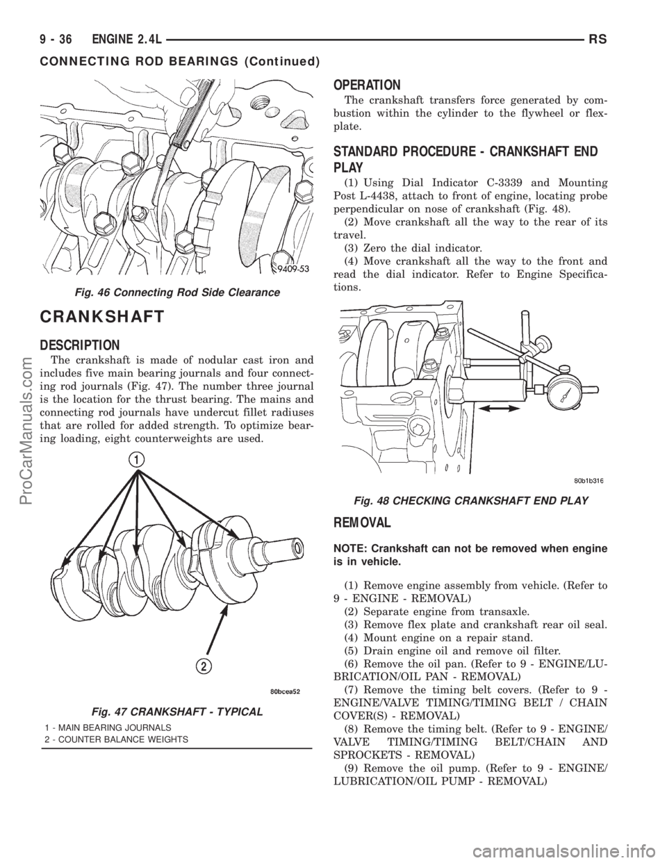
DESCRIPTION
The crankshaft is made of nodular cast iron and
includes five main bearing journals and four connect-
ing rod journals (Fig. 47). The number three journal
is the location for the thrust bearing. The mains and
connecting rod journals have undercut fillet radiuses
that are rolled for added strength. To optimize bear-
ing loading, eight counterweights are used.
OPERATION
The crankshaft transfers force generated by com-
bustion within the cylinder to the flywheel or flex-
plate.
STANDARD PROCEDURE - CRANKSHAFT END
PLAY
(1) Using Dial Indicator C-3339 and Mounting
Post L-4438, attach to front of engine, locating probe
perpendicular on nose of crankshaft (Fig. 48).
(2) Move crankshaft all the way to the rear of its
travel.
(3) Zero the dial indicator.
(4) Move crankshaft all the way to the front and
read the dial indicator. Refer to Engine Specifica-
tions.
REMOVAL
NOTE: Crankshaft can not be removed when engine
is in vehicle.
(1) Remove engine assembly from vehicle. (Refer to
9 - ENGINE - REMOVAL)
(2) Separate engine from transaxle.
(3) Remove flex plate and crankshaft rear oil seal.
(4) Mount engine on a repair stand.
(5) Drain engine oil and remove oil filter.
(6) Remove the oil pan. (Refer to 9 - ENGINE/LU-
BRICATION/OIL PAN - REMOVAL)
(7) Remove the timing belt covers. (Refer to 9 -
ENGINE/VALVE TIMING/TIMING BELT / CHAIN
COVER(S) - REMOVAL)
(8) Remove the timing belt. (Refer to 9 - ENGINE/
VALVE TIMING/TIMING BELT/CHAIN AND
SPROCKETS - REMOVAL)
(9) Remove the oil pump. (Refer to 9 - ENGINE/
LUBRICATION/OIL PUMP - REMOVAL)
Fig. 46 Connecting Rod Side Clearance
Fig. 47 CRANKSHAFT - TYPICAL
1 - MAIN BEARING JOURNALS
2 - COUNTER BALANCE WEIGHTS
Fig. 48 CHECKING CRANKSHAFT END PLAY
9 - 36 ENGINE 2.4LRS
CONNECTING ROD BEARINGS (Continued)
ProCarManuals.com
Page 1195 of 2321
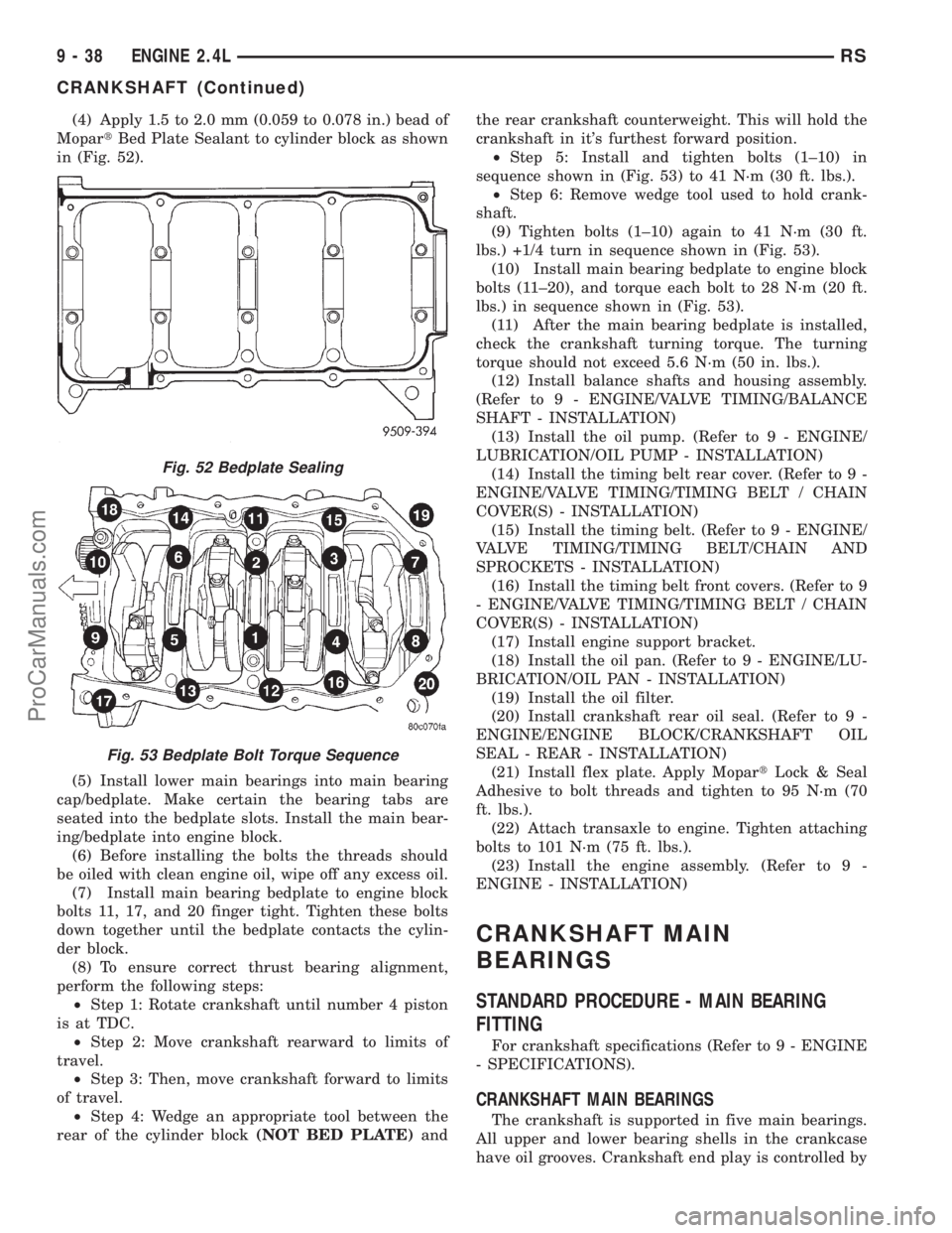
(4) Apply 1.5 to 2.0 mm (0.059 to 0.078 in.) bead of
MopartBed Plate Sealant to cylinder block as shown
in (Fig. 52).
(5) Install lower main bearings into main bearing
cap/bedplate. Make certain the bearing tabs are
seated into the bedplate slots. Install the main bear-
ing/bedplate into engine block.
(6) Before installing the bolts the threads should
be oiled with clean engine oil, wipe off any excess oil.
(7) Install main bearing bedplate to engine block
bolts 11, 17, and 20 finger tight. Tighten these bolts
down together until the bedplate contacts the cylin-
der block.
(8) To ensure correct thrust bearing alignment,
perform the following steps:
²Step 1: Rotate crankshaft until number 4 piston
is at TDC.
²Step 2: Move crankshaft rearward to limits of
travel.
²Step 3: Then, move crankshaft forward to limits
of travel.
²Step 4: Wedge an appropriate tool between the
rear of the cylinder block(NOT BED PLATE)andthe rear crankshaft counterweight. This will hold the
crankshaft in it's furthest forward position.
²Step 5: Install and tighten bolts (1±10) in
sequence shown in (Fig. 53) to 41 N´m (30 ft. lbs.).
²Step 6: Remove wedge tool used to hold crank-
shaft.
(9) Tighten bolts (1±10) again to 41 N´m (30 ft.
lbs.) +1/4 turn in sequence shown in (Fig. 53).
(10) Install main bearing bedplate to engine block
bolts (11±20), and torque each bolt to 28 N´m (20 ft.
lbs.) in sequence shown in (Fig. 53).
(11) After the main bearing bedplate is installed,
check the crankshaft turning torque. The turning
torque should not exceed 5.6 N´m (50 in. lbs.).
(12) Install balance shafts and housing assembly.
(Refer to 9 - ENGINE/VALVE TIMING/BALANCE
SHAFT - INSTALLATION)
(13) Install the oil pump. (Refer to 9 - ENGINE/
LUBRICATION/OIL PUMP - INSTALLATION)
(14) Install the timing belt rear cover. (Refer to 9 -
ENGINE/VALVE TIMING/TIMING BELT / CHAIN
COVER(S) - INSTALLATION)
(15) Install the timing belt. (Refer to 9 - ENGINE/
VALVE TIMING/TIMING BELT/CHAIN AND
SPROCKETS - INSTALLATION)
(16) Install the timing belt front covers. (Refer to 9
- ENGINE/VALVE TIMING/TIMING BELT / CHAIN
COVER(S) - INSTALLATION)
(17) Install engine support bracket.
(18) Install the oil pan. (Refer to 9 - ENGINE/LU-
BRICATION/OIL PAN - INSTALLATION)
(19) Install the oil filter.
(20) Install crankshaft rear oil seal. (Refer to 9 -
ENGINE/ENGINE BLOCK/CRANKSHAFT OIL
SEAL - REAR - INSTALLATION)
(21) Install flex plate. Apply MopartLock & Seal
Adhesive to bolt threads and tighten to 95 N´m (70
ft. lbs.).
(22) Attach transaxle to engine. Tighten attaching
bolts to 101 N´m (75 ft. lbs.).
(23) Install the engine assembly. (Refer to 9 -
ENGINE - INSTALLATION)
CRANKSHAFT MAIN
BEARINGS
STANDARD PROCEDURE - MAIN BEARING
FITTING
For crankshaft specifications (Refer to 9 - ENGINE
- SPECIFICATIONS).
CRANKSHAFT MAIN BEARINGS
The crankshaft is supported in five main bearings.
All upper and lower bearing shells in the crankcase
have oil grooves. Crankshaft end play is controlled by
Fig. 52 Bedplate Sealing
Fig. 53 Bedplate Bolt Torque Sequence
9 - 38 ENGINE 2.4LRS
CRANKSHAFT (Continued)
ProCarManuals.com