2001 DODGE TOWN AND COUNTRY weight
[x] Cancel search: weightPage 1197 of 2321
(5) Install lower main bearings into main bearing
cap/bedplate. Make certain the bearing tabs are
seated into the bedplate slots.
(6) Position the main bearing/bedplate onto the
engine block.
(7) Before installing bolts, lubricate the threads
with clean engine oil, wipe off any excess oil.
(8) Install main bearing bedplate to engine block
bolts 11, 17 and 20 finger tight. Tighten these bolts
down together until the bedplate contacts the cylin-
der block.
(9) To ensure correct thrust bearing alignment,
perform the following steps:
²Step 1: Rotate crankshaft until number 4 piston
is at TDC.
²Step 2: Move crankshaft rearward to limits of
travel.
²Step 3: Then, move crankshaft forward to limits
of travel.
²Step 4: Wedge an appropriate tool between the
rear of the cylinder block(NOT BED PLATE)and
the rear crankshaft counterweight. This will hold the
crankshaft in it's furthest forward position.
²Step 5: Install and tighten bolts (1±10) in
sequence shown in (Fig. 57) to 41 N´m (30 ft. lbs.).
²Step 6: Remove wedge tool used to hold crank-
shaft.
(10) Tighten bolts (1±10) again to 41 N´m (30 ft.
lbs.)PLUS1/4 turn in sequence shown in (Fig. 57).
(11) Install main bearing bedplate to engine block
bolts (11±20), and torque each bolt to 28 N´m (20 ft.
lbs.) in sequence shown in (Fig. 57).
(12) After the main bearing bedplate is installed,
check the crankshaft turning torque. The turning
torque should not exceed 5.6 N´m (50 in. lbs.).
CRANKSHAFT OIL SEAL -
FRONT
REMOVAL
(1) Remove the crankshaft vibration damper.
(Refer to 9 - ENGINE/ENGINE BLOCK/VIBRATION
DAMPER - REMOVAL)
(2) Remove timing belt. (Refer to 9 - ENGINE/
VALVE TIMING/TIMING BELT/CHAIN AND
SPROCKETS - REMOVAL)
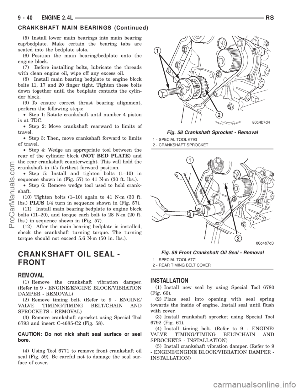
(3) Remove crankshaft sprocket using Special Tool
6793 and insert C-4685-C2 (Fig. 58).
CAUTION: Do not nick shaft seal surface or seal
bore.
(4) Using Tool 6771 to remove front crankshaft oil
seal (Fig. 59). Be careful not to damage the seal sur-
face of cover.INSTALLATION
(1) Install new seal by using Special Tool 6780
(Fig. 60).
(2) Place seal into opening with seal spring
towards the inside of engine. Install seal until flush
with cover.
(3) Install crankshaft sprocket using Special Tool
6792 (Fig. 61).
(4) Install timing belt. (Refer to 9 - ENGINE/
VALVE TIMING/TIMING BELT/CHAIN AND
SPROCKETS - INSTALLATION)
(5) Install crankshaft vibration damper. (Refer to 9
- ENGINE/ENGINE BLOCK/VIBRATION DAMPER -
INSTALLATION)
Fig. 58 Crankshaft Sprocket - Removal
1 - SPECIAL TOOL 6793
2 - CRANKSHAFT SPROCKET
Fig. 59 Front Crankshaft Oil Seal - Removal
1 - SPECIAL TOOL 6771
2 - REAR TIMING BELT COVER
9 - 40 ENGINE 2.4LRS
CRANKSHAFT MAIN BEARINGS (Continued)
ProCarManuals.com
Page 1241 of 2321
(53) Lower the vehicle.
(54) Remove the power steering pump and set
aside.
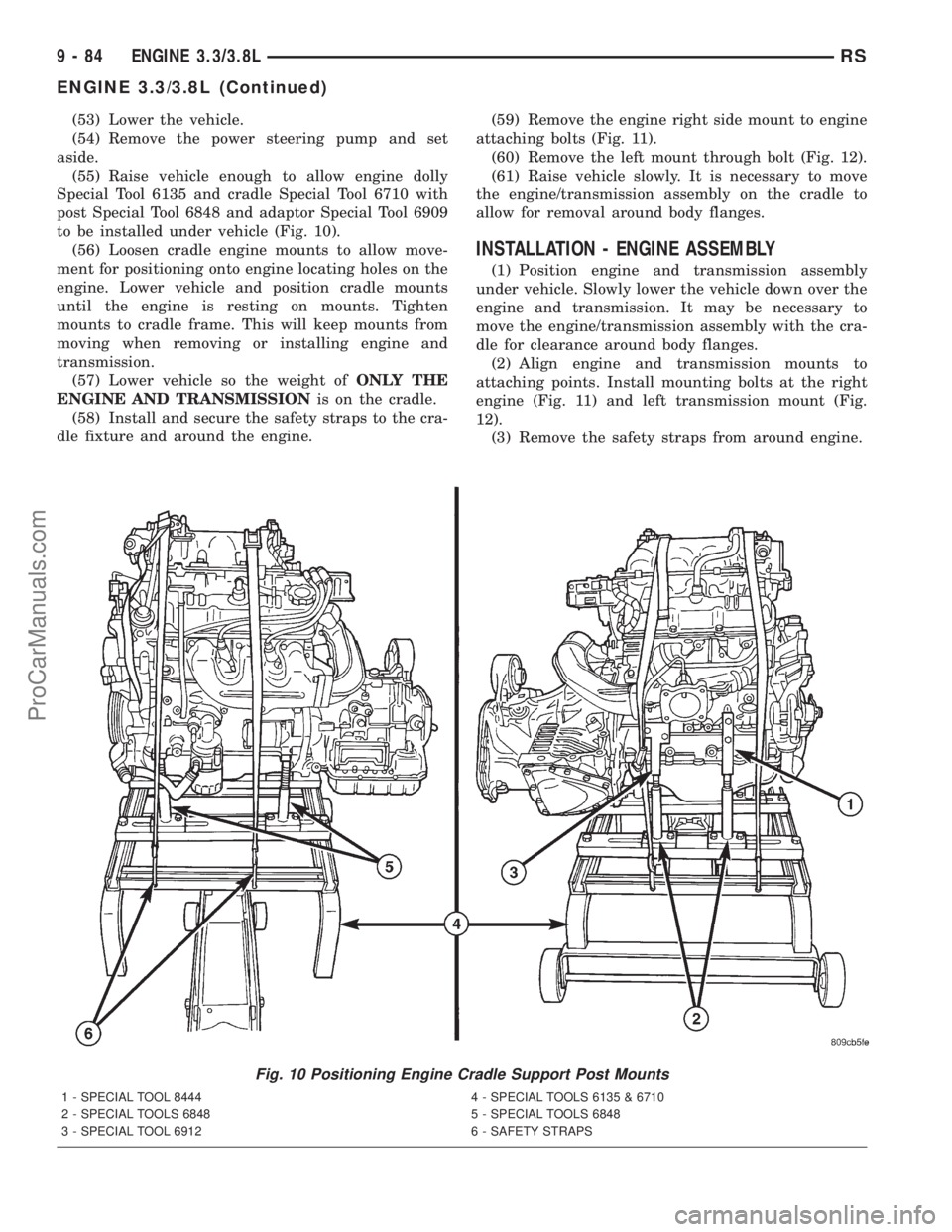
(55) Raise vehicle enough to allow engine dolly
Special Tool 6135 and cradle Special Tool 6710 with
post Special Tool 6848 and adaptor Special Tool 6909
to be installed under vehicle (Fig. 10).
(56) Loosen cradle engine mounts to allow move-
ment for positioning onto engine locating holes on the
engine. Lower vehicle and position cradle mounts
until the engine is resting on mounts. Tighten
mounts to cradle frame. This will keep mounts from
moving when removing or installing engine and
transmission.
(57) Lower vehicle so the weight ofONLY THE
ENGINE AND TRANSMISSIONis on the cradle.
(58) Install and secure the safety straps to the cra-
dle fixture and around the engine.(59) Remove the engine right side mount to engine
attaching bolts (Fig. 11).
(60) Remove the left mount through bolt (Fig. 12).
(61) Raise vehicle slowly. It is necessary to move
the engine/transmission assembly on the cradle to
allow for removal around body flanges.
INSTALLATION - ENGINE ASSEMBLY
(1) Position engine and transmission assembly
under vehicle. Slowly lower the vehicle down over the
engine and transmission. It may be necessary to
move the engine/transmission assembly with the cra-
dle for clearance around body flanges.
(2) Align engine and transmission mounts to
attaching points. Install mounting bolts at the right
engine (Fig. 11) and left transmission mount (Fig.
12).
(3) Remove the safety straps from around engine.
Fig. 10 Positioning Engine Cradle Support Post Mounts
1 - SPECIAL TOOL 8444 4 - SPECIAL TOOLS 6135 & 6710
2 - SPECIAL TOOLS 6848 5 - SPECIAL TOOLS 6848
3 - SPECIAL TOOL 6912 6 - SAFETY STRAPS
9 - 84 ENGINE 3.3/3.8LRS
ENGINE 3.3/3.8L (Continued)
ProCarManuals.com
Page 1244 of 2321
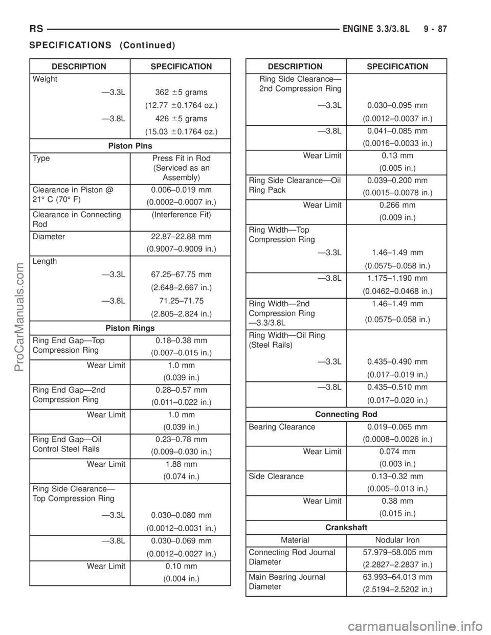
DESCRIPTION SPECIFICATION
Weight
Ð3.3L 36265 grams
(12.7760.1764 oz.)
Ð3.8L 42665 grams
(15.0360.1764 oz.)
Piston Pins
Type Press Fit in Rod
(Serviced as an
Assembly)
Clearance in Piston @
21É C (70É F)0.006±0.019 mm
(0.0002±0.0007 in.)
Clearance in Connecting
Rod(Interference Fit)
Diameter 22.87±22.88 mm
(0.9007±0.9009 in.)
Length
Ð3.3L 67.25±67.75 mm
(2.648±2.667 in.)
Ð3.8L 71.25±71.75
(2.805±2.824 in.)
Piston Rings
Ring End GapÐTop
Compression Ring0.18±0.38 mm
(0.007±0.015 in.)
Wear Limit 1.0 mm
(0.039 in.)
Ring End GapÐ2nd
Compression Ring0.28±0.57 mm
(0.011±0.022 in.)
Wear Limit 1.0 mm
(0.039 in.)
Ring End GapÐOil
Control Steel Rails0.23±0.78 mm
(0.009±0.030 in.)
Wear Limit 1.88 mm
(0.074 in.)
Ring Side ClearanceÐ
Top Compression Ring
Ð3.3L 0.030±0.080 mm
(0.0012±0.0031 in.)
Ð3.8L 0.030±0.069 mm
(0.0012±0.0027 in.)
Wear Limit 0.10 mm
(0.004 in.)DESCRIPTION SPECIFICATION
Ring Side ClearanceÐ
2nd Compression Ring
Ð3.3L 0.030±0.095 mm
(0.0012±0.0037 in.)
Ð3.8L 0.041±0.085 mm
(0.0016±0.0033 in.)
Wear Limit 0.13 mm
(0.005 in.)
Ring Side ClearanceÐOil
Ring Pack0.039±0.200 mm
(0.0015±0.0078 in.)
Wear Limit 0.266 mm
(0.009 in.)
Ring WidthÐTop
Compression Ring
Ð3.3L 1.46±1.49 mm
(0.0575±0.058 in.)
Ð3.8L 1.175±1.190 mm
(0.0462±0.0468 in.)
Ring WidthÐ2nd
Compression Ring
Ð3.3/3.8L1.46±1.49 mm
(0.0575±0.058 in.)
Ring WidthÐOil Ring
(Steel Rails)
Ð3.3L 0.435±0.490 mm
(0.017±0.019 in.)
Ð3.8L 0.435±0.510 mm
(0.017±0.020 in.)
Connecting Rod
Bearing Clearance 0.019±0.065 mm
(0.0008±0.0026 in.)
Wear Limit 0.074 mm
(0.003 in.)
Side Clearance 0.13±0.32 mm
(0.005±0.013 in.)
Wear Limit 0.38 mm
(0.015 in.)
Crankshaft
Material Nodular Iron
Connecting Rod Journal
Diameter57.979±58.005 mm
(2.2827±2.2837 in.)
Main Bearing Journal
Diameter63.993±64.013 mm
(2.5194±2.5202 in.)
RSENGINE 3.3/3.8L9-87
SPECIFICATIONS (Continued)
ProCarManuals.com
Page 1270 of 2321
CRANKSHAFT MAIN
BEARINGS
STANDARD PROCEDURE - MAIN BEARING
FITTING
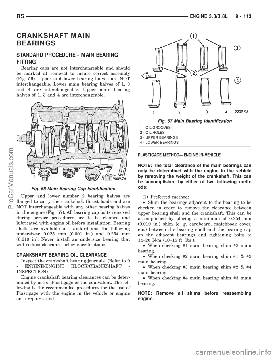
Bearing caps are not interchangeable and should
be marked at removal to insure correct assembly
(Fig. 56). Upper and lower bearing halves are NOT
interchangeable. Lower main bearing halves of 1, 3
and 4 are interchangeable. Upper main bearing
halves of 1, 3 and 4 are interchangeable.
Upper and lower number 2 bearing halves are
flanged to carry the crankshaft thrust loads and are
NOT interchangeable with any other bearing halves
in the engine (Fig. 57). All bearing cap bolts removed
during service procedures are to be cleaned and
lubricated with engine oil before installation. Bearing
shells are available in standard and the following
undersizes: 0.025 mm (0.001 in.) and 0.254 mm
(0.010 in). Never install an undersize bearing that
will reduce clearance below specifications.
CRANKSHAFT BEARING OIL CLEARANCE
Inspect the crankshaft bearing journals. (Refer to 9
- ENGINE/ENGINE BLOCK/CRANKSHAFT -
INSPECTION)
Engine crankshaft bearing clearances can be deter-
mined by use of Plastigage or the equivalent. The fol-
lowing is the recommended procedures for the use of
Plastigage with the engine in the vehicle or engine
on a repair stand.PLASTIGAGE METHODÐENGINE IN-VEHICLE
NOTE: The total clearance of the main bearings can
only be determined with the engine in the vehicle
by removing the weight of the crankshaft. This can
be accomplished by either of two following meth-
ods:
(1) Preferred method:
²Shim the bearings adjacent to the bearing to be
checked in order to remove the clearance between
upper bearing shell and the crankshaft. This can be
accomplished by placing a minimum of 0.254 mm
(0.010 in.) shim (e. g. cardboard, matchbook cover,
etc.) between the bearing shell and the bearing cap
on the adjacent bearings and tightening bolts to
14±20 N´m (10±15 ft. lbs.).
²When checking #1 main bearing shim #2 main
bearing.
²When checking #2 main bearing shim #1 & #3
main bearing.
²When checking #3 main bearing shim #2 & #4
main bearing.
²When checking #4 main bearing shim #3 main
bearing.
NOTE: Remove all shims before reassembling
engine.
Fig. 56 Main Bearing Cap Identification
Fig. 57 Main Bearing Identification
1 - OIL GROOVES
2 - OIL HOLES
3 - UPPER BEARINGS
4 - LOWER BEARINGS
RSENGINE 3.3/3.8L9 - 113
ProCarManuals.com
Page 1271 of 2321
(2) Alternative Method:
²Support the weight of the crankshaft with a jack
under the counterweight adjacent to the bearing
being checked.
(3) Remove oil film from surface to be checked.
Plastigage is soluble in oil.
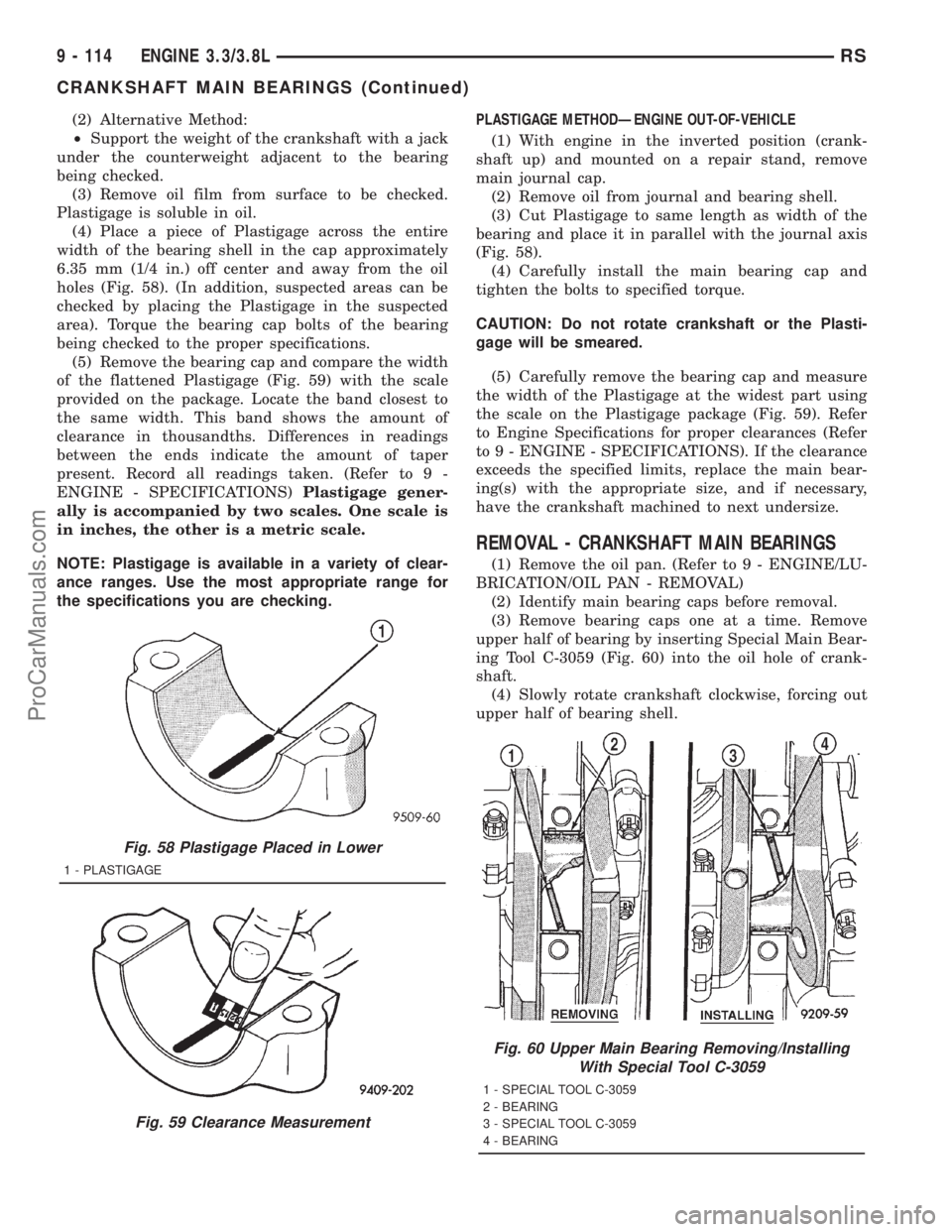
(4) Place a piece of Plastigage across the entire
width of the bearing shell in the cap approximately
6.35 mm (1/4 in.) off center and away from the oil
holes (Fig. 58). (In addition, suspected areas can be
checked by placing the Plastigage in the suspected
area). Torque the bearing cap bolts of the bearing
being checked to the proper specifications.
(5) Remove the bearing cap and compare the width
of the flattened Plastigage (Fig. 59) with the scale
provided on the package. Locate the band closest to
the same width. This band shows the amount of
clearance in thousandths. Differences in readings
between the ends indicate the amount of taper
present. Record all readings taken. (Refer to 9 -
ENGINE - SPECIFICATIONS)Plastigage gener-
ally is accompanied by two scales. One scale is
in inches, the other is a metric scale.
NOTE: Plastigage is available in a variety of clear-
ance ranges. Use the most appropriate range for
the specifications you are checking.PLASTIGAGE METHODÐENGINE OUT-OF-VEHICLE
(1) With engine in the inverted position (crank-
shaft up) and mounted on a repair stand, remove
main journal cap.
(2) Remove oil from journal and bearing shell.
(3) Cut Plastigage to same length as width of the
bearing and place it in parallel with the journal axis
(Fig. 58).
(4) Carefully install the main bearing cap and
tighten the bolts to specified torque.
CAUTION: Do not rotate crankshaft or the Plasti-
gage will be smeared.
(5) Carefully remove the bearing cap and measure
the width of the Plastigage at the widest part using
the scale on the Plastigage package (Fig. 59). Refer
to Engine Specifications for proper clearances (Refer
to 9 - ENGINE - SPECIFICATIONS). If the clearance
exceeds the specified limits, replace the main bear-
ing(s) with the appropriate size, and if necessary,
have the crankshaft machined to next undersize.
REMOVAL - CRANKSHAFT MAIN BEARINGS
(1) Remove the oil pan. (Refer to 9 - ENGINE/LU-
BRICATION/OIL PAN - REMOVAL)
(2) Identify main bearing caps before removal.
(3) Remove bearing caps one at a time. Remove
upper half of bearing by inserting Special Main Bear-
ing Tool C-3059 (Fig. 60) into the oil hole of crank-
shaft.
(4) Slowly rotate crankshaft clockwise, forcing out
upper half of bearing shell.
Fig. 58 Plastigage Placed in Lower
1 - PLASTIGAGE
Fig. 59 Clearance Measurement
Fig. 60 Upper Main Bearing Removing/Installing
With Special Tool C-3059
1 - SPECIAL TOOL C-3059
2 - BEARING
3 - SPECIAL TOOL C-3059
4 - BEARING
9 - 114 ENGINE 3.3/3.8LRS
CRANKSHAFT MAIN BEARINGS (Continued)
ProCarManuals.com
Page 1272 of 2321
INSTALLATION - CRANKSHAFT MAIN
BEARINGS
NOTE: One main bearing should be selectively fit-
ted while all other main bearing caps are properly
tightened.
(1) For main bearing fitting procedure, (Refer to 9
- ENGINE/ENGINE BLOCK/CRANKSHAFT MAIN
BEARINGS - STANDARD PROCEDURE)
(2) Start bearing in place, and insert Main Bearing
Tool C-3059 into oil hole of crankshaft (Fig. 60).
(3) Slowly rotate crankshaft counterclockwise slid-
ing the bearing into position. Remove Special Main
Bearing Tool C-3059.
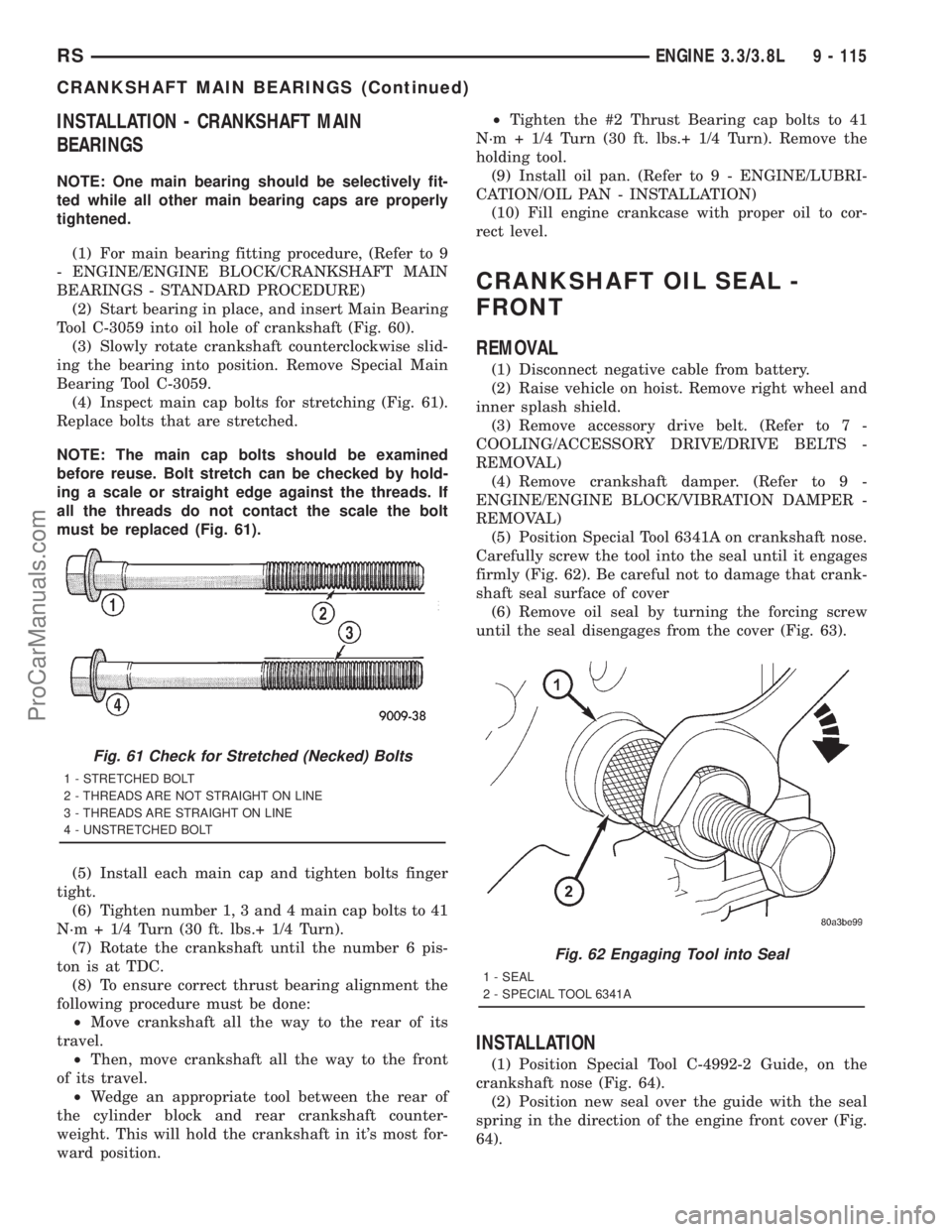
(4) Inspect main cap bolts for stretching (Fig. 61).
Replace bolts that are stretched.
NOTE: The main cap bolts should be examined
before reuse. Bolt stretch can be checked by hold-
ing a scale or straight edge against the threads. If
all the threads do not contact the scale the bolt
must be replaced (Fig. 61).
(5) Install each main cap and tighten bolts finger
tight.
(6) Tighten number 1, 3 and 4 main cap bolts to 41
N´m + 1/4 Turn (30 ft. lbs.+ 1/4 Turn).
(7) Rotate the crankshaft until the number 6 pis-
ton is at TDC.
(8) To ensure correct thrust bearing alignment the
following procedure must be done:
²Move crankshaft all the way to the rear of its
travel.
²Then, move crankshaft all the way to the front
of its travel.
²Wedge an appropriate tool between the rear of
the cylinder block and rear crankshaft counter-
weight. This will hold the crankshaft in it's most for-
ward position.²Tighten the #2 Thrust Bearing cap bolts to 41
N´m + 1/4 Turn (30 ft. lbs.+ 1/4 Turn). Remove the
holding tool.
(9) Install oil pan. (Refer to 9 - ENGINE/LUBRI-
CATION/OIL PAN - INSTALLATION)
(10) Fill engine crankcase with proper oil to cor-
rect level.
CRANKSHAFT OIL SEAL -
FRONT
REMOVAL
(1) Disconnect negative cable from battery.
(2) Raise vehicle on hoist. Remove right wheel and
inner splash shield.
(3) Remove accessory drive belt. (Refer to 7 -
COOLING/ACCESSORY DRIVE/DRIVE BELTS -
REMOVAL)
(4) Remove crankshaft damper. (Refer to 9 -
ENGINE/ENGINE BLOCK/VIBRATION DAMPER -
REMOVAL)
(5) Position Special Tool 6341A on crankshaft nose.
Carefully screw the tool into the seal until it engages
firmly (Fig. 62). Be careful not to damage that crank-
shaft seal surface of cover
(6) Remove oil seal by turning the forcing screw
until the seal disengages from the cover (Fig. 63).
INSTALLATION
(1) Position Special Tool C-4992-2 Guide, on the
crankshaft nose (Fig. 64).
(2) Position new seal over the guide with the seal
spring in the direction of the engine front cover (Fig.
64).
Fig. 61 Check for Stretched (Necked) Bolts
1 - STRETCHED BOLT
2 - THREADS ARE NOT STRAIGHT ON LINE
3 - THREADS ARE STRAIGHT ON LINE
4 - UNSTRETCHED BOLT
Fig. 62 Engaging Tool into Seal
1 - SEAL
2 - SPECIAL TOOL 6341A
RSENGINE 3.3/3.8L9 - 115
CRANKSHAFT MAIN BEARINGS (Continued)
ProCarManuals.com
Page 1323 of 2321
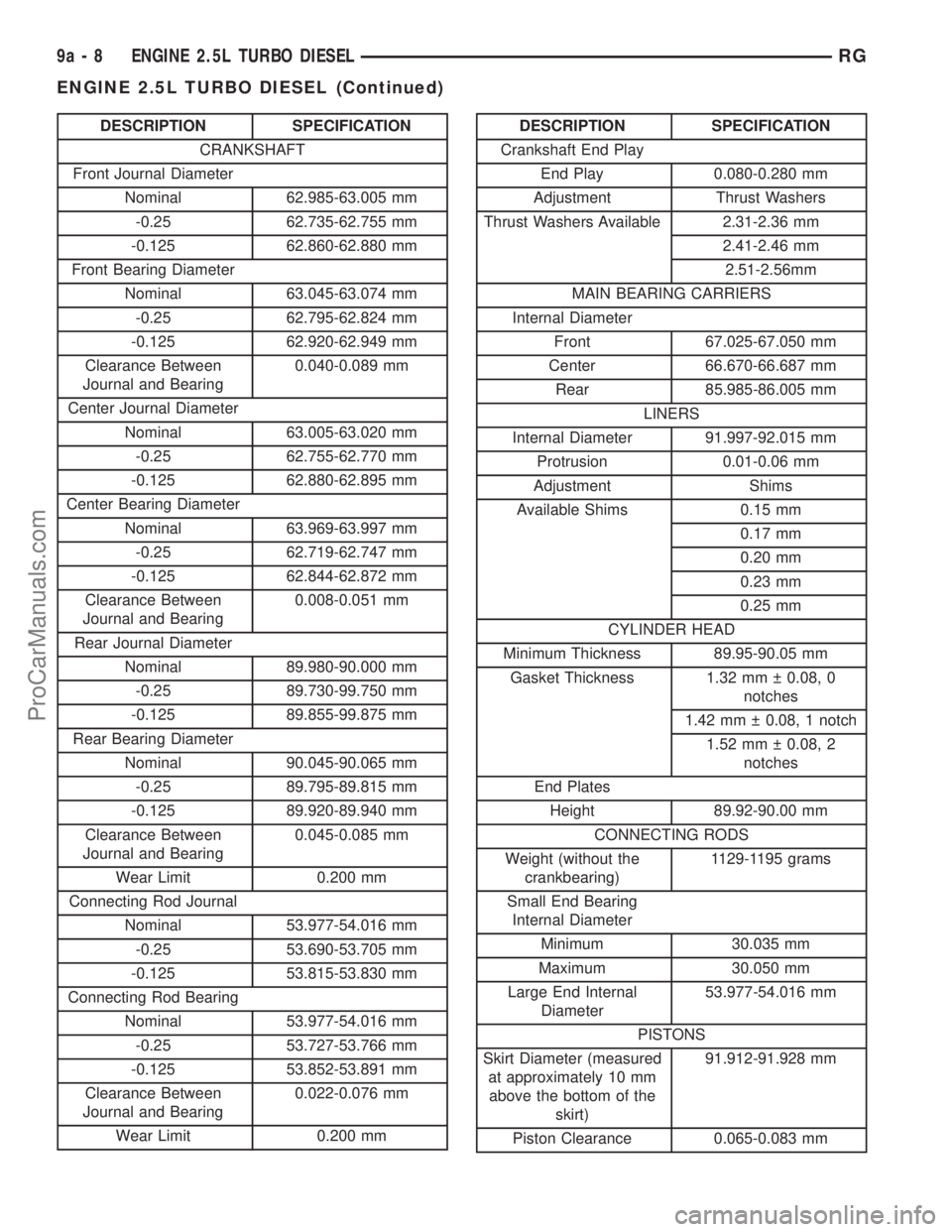
DESCRIPTION SPECIFICATION
CRANKSHAFT
Front Journal Diameter
Nominal 62.985-63.005 mm
-0.25 62.735-62.755 mm
-0.125 62.860-62.880 mm
Front Bearing Diameter
Nominal 63.045-63.074 mm
-0.25 62.795-62.824 mm
-0.125 62.920-62.949 mm
Clearance Between
Journal and Bearing0.040-0.089 mm
Center Journal Diameter
Nominal 63.005-63.020 mm
-0.25 62.755-62.770 mm
-0.125 62.880-62.895 mm
Center Bearing Diameter
Nominal 63.969-63.997 mm
-0.25 62.719-62.747 mm
-0.125 62.844-62.872 mm
Clearance Between
Journal and Bearing0.008-0.051 mm
Rear Journal Diameter
Nominal 89.980-90.000 mm
-0.25 89.730-99.750 mm
-0.125 89.855-99.875 mm
Rear Bearing Diameter
Nominal 90.045-90.065 mm
-0.25 89.795-89.815 mm
-0.125 89.920-89.940 mm
Clearance Between
Journal and Bearing0.045-0.085 mm
Wear Limit 0.200 mm
Connecting Rod Journal
Nominal 53.977-54.016 mm
-0.25 53.690-53.705 mm
-0.125 53.815-53.830 mm
Connecting Rod Bearing
Nominal 53.977-54.016 mm
-0.25 53.727-53.766 mm
-0.125 53.852-53.891 mm
Clearance Between
Journal and Bearing0.022-0.076 mm
Wear Limit 0.200 mmDESCRIPTION SPECIFICATION
Crankshaft End Play
End Play 0.080-0.280 mm
Adjustment Thrust Washers
Thrust Washers Available 2.31-2.36 mm
2.41-2.46 mm
2.51-2.56mm
MAIN BEARING CARRIERS
Internal Diameter
Front 67.025-67.050 mm
Center 66.670-66.687 mm
Rear 85.985-86.005 mm
LINERS
Internal Diameter 91.997-92.015 mm
Protrusion 0.01-0.06 mm
Adjustment Shims
Available Shims 0.15 mm
0.17 mm
0.20 mm
0.23 mm
0.25 mm
CYLINDER HEAD
Minimum Thickness 89.95-90.05 mm
Gasket Thickness 1.32 mm 0.08, 0
notches
1.42 mm 0.08, 1 notch
1.52 mm 0.08, 2
notches
End Plates
Height 89.92-90.00 mm
CONNECTING RODS
Weight (without the
crankbearing)1129-1195 grams
Small End Bearing
Internal Diameter
Minimum 30.035 mm
Maximum 30.050 mm
Large End Internal
Diameter53.977-54.016 mm
PISTONS
Skirt Diameter (measured
at approximately 10 mm
above the bottom of the
skirt)91.912-91.928 mm
Piston Clearance 0.065-0.083 mm
9a - 8 ENGINE 2.5L TURBO DIESELRG
ENGINE 2.5L TURBO DIESEL (Continued)
ProCarManuals.com
Page 1354 of 2321
(4) Skirt wear should not exceed 0.1 mm (.00039
in.).
(5) The clearance between the cylinder liner and
piston should not exceed 0.065-0.083 mm
(.0025-.0032 in.).
(6) Make sure the weight of the pistons does not
differ by more than 5 g.
CONNECTING RODS
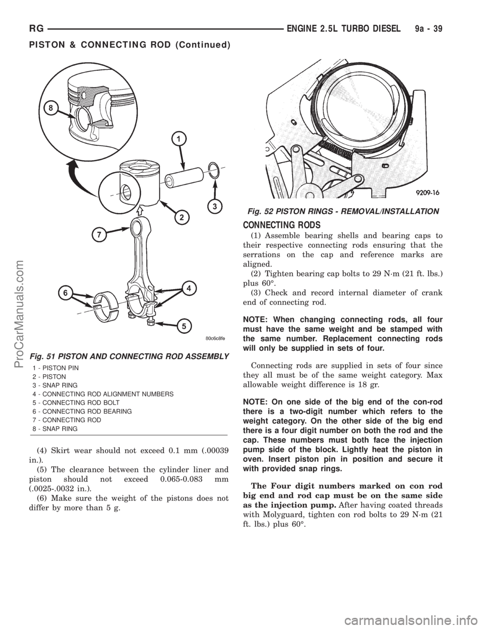
(1) Assemble bearing shells and bearing caps to
their respective connecting rods ensuring that the
serrations on the cap and reference marks are
aligned.
(2) Tighten bearing cap bolts to 29 N´m (21 ft. lbs.)
plus 60É.
(3) Check and record internal diameter of crank
end of connecting rod.
NOTE: When changing connecting rods, all four
must have the same weight and be stamped with
the same number. Replacement connecting rods
will only be supplied in sets of four.
Connecting rods are supplied in sets of four since
they all must be of the same weight category. Max
allowable weight difference is 18 gr.
NOTE: On one side of the big end of the con-rod
there is a two-digit number which refers to the
weight category. On the other side of the big end
there is a four digit number on both the rod and the
cap. These numbers must both face the injection
pump side of the block. Lightly heat the piston in
oven. Insert piston pin in position and secure it
with provided snap rings.
The Four digit numbers marked on con rod
big end and rod cap must be on the same side
as the injection pump.After having coated threads
with Molyguard, tighten con rod bolts to 29 N´m (21
ft. lbs.) plus 60É.
Fig. 51 PISTON AND CONNECTING ROD ASSEMBLY
1 - PISTON PIN
2 - PISTON
3 - SNAP RING
4 - CONNECTING ROD ALIGNMENT NUMBERS
5 - CONNECTING ROD BOLT
6 - CONNECTING ROD BEARING
7 - CONNECTING ROD
8 - SNAP RING
Fig. 52 PISTON RINGS - REMOVAL/INSTALLATION
RGENGINE 2.5L TURBO DIESEL9a-39
PISTON & CONNECTING ROD (Continued)
ProCarManuals.com