2001 DODGE RAM air conditioning
[x] Cancel search: air conditioningPage 2748 of 2889
tom of the a/c heater control panel. Refer to Heated
Mirrors for more information on this feature.
The heater-only or a/c heater control panel cannot
be repaired. If faulty or damaged, the entire unit
must be replaced. The control knobs and the illumi-
nation lamps are available for service replacement.
DIAGNOSIS AND TESTING - A/C HEATER
CONTROL
Satisfactory heater and air conditioner perfor-
mance depends upon proper operation and adjust-
ment of all operating controls and refrigeration
system components. For circuit descriptions and dia-
grams, (Refer to Appropriate Wiring Information).
These inspections, tests, and adjustments should be
used to locate the cause of a malfunction.
Operation must be tested as described in the fol-
lowing sequence:
(1) Inspect and adjust the serpentine drive belt.
Refer to Cooling for the procedures.
(2) Start the engine and hold the idle speed at
1,300 rpm.
(3) On vehicles with air conditioning, turn the
temperature control knob to the extreme counter-
clockwise (Cool) position, and set the mode control
switch knob to the Bi-Level (A/C) position. The out-
side (recirculation) air door should be open to outside
air. If not OK, (Refer to 24 - HEATING & AIR CON-
DITIONING/CONTROLS - DIAGNOSIS AND TEST-
ING - VACUUM SYSTEM).
(4) Open the vehicle windows. Test the blower
motor operation in all speeds. If not OK, (Refer to 24
- HEATING & AIR CONDITIONING/DISTRIBU-
TION/BLOWER MOTOR - DIAGNOSIS AND TEST-
ING).
(5) On vehicles with air conditioning, the compres-
sor should be running and the air conditioning sys-
tem in operation unless the ambient air temperature
is below about -1É C (30É F). If not OK, (Refer to 24 -
HEATING & AIR CONDITIONING - DIAGNOSIS
AND TESTING - A/C PERFORMANCE).
(6) Check the mode control switch operation. The
heater and air conditioner systems should respond as
described in the owner's manual in the vehicle glove
box to each mode selected. Reduce the engine speed
to normal idle. The vacuum will be high at low idle
and the vacuum actuators should respond quickly. If
not OK, (Refer to 24 - HEATING & AIR CONDI-
TIONING/CONTROLS - DIAGNOSIS AND TEST-
ING - VACUUM SYSTEM).
(7) If the vacuum tests, and the electrical compo-
nent and circuit tests reveal no problems, disassem-
ble the HVAC housing to inspect for mechanical
misalignment or binding of the mode doors. (Refer to
24 - HEATING & AIR CONDITIONING/DISTRIBU-
TION/HVAC HOUSING - DISASSEMBLY)
REMOVAL
WARNING: ON VEHICLES EQUIPPED WITH AIR-
BAGS, DISABLE THE AIRBAG SYSTEM BEFORE
ATTEMPTING ANY STEERING WHEEL, STEERING
COLUMN, OR INSTRUMENT PANEL COMPONENT
DIAGNOSIS OR SERVICE. DISCONNECT AND ISO-
LATE THE BATTERY NEGATIVE (GROUND) CABLE,
THEN WAIT TWO MINUTES FOR THE AIRBAG SYS-
TEM CAPACITOR TO DISCHARGE BEFORE PER-
FORMING FURTHER DIAGNOSIS OR SERVICE. THIS
IS THE ONLY SURE WAY TO DISABLE THE AIRBAG
SYSTEM. FAILURE TO TAKE THE PROPER PRE-
CAUTIONS COULD RESULT IN AN ACCIDENTAL
AIRBAG DEPLOYMENT AND POSSIBLE PERSONAL
INJURY.
(1) Disconnect and isolate the battery negative
cable.
(2) Reach under the instrument panel near the
driver side of the floor panel transmission tunnel and
unplug the a/c heater control to HVAC housing vac-
uum harness connector.
(3) While still reaching under the instrument
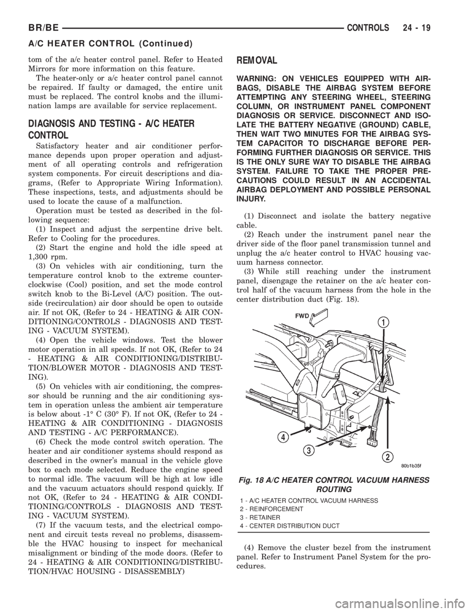
panel, disengage the retainer on the a/c heater con-
trol half of the vacuum harness from the hole in the
center distribution duct (Fig. 18).
(4) Remove the cluster bezel from the instrument
panel. Refer to Instrument Panel System for the pro-
cedures.
Fig. 18 A/C HEATER CONTROL VACUUM HARNESS
ROUTING
1 - A/C HEATER CONTROL VACUUM HARNESS
2 - REINFORCEMENT
3 - RETAINER
4 - CENTER DISTRIBUTION DUCT
BR/BECONTROLS 24 - 19
A/C HEATER CONTROL (Continued)
Page 2749 of 2889
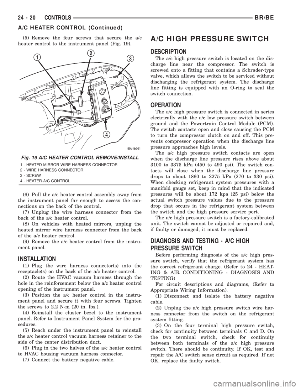
(5) Remove the four screws that secure the a/c
heater control to the instrument panel (Fig. 19).
(6) Pull the a/c heater control assembly away from
the instrument panel far enough to access the con-
nections on the back of the control.
(7) Unplug the wire harness connector from the
back of the a/c heater control.
(8) On vehicles with heated mirrors, unplug the
heated mirror wire harness connector from the back
of the a/c heater control.
(9) Remove the a/c heater control from the instru-
ment panel.
INSTALLATION
(1) Plug the wire harness connector(s) into the
receptacle(s) on the back of the a/c heater control.
(2) Route the HVAC vacuum harness through the
hole in the reinforcement below the a/c heater control
opening of the instrument panel.
(3) Position the a/c heater control in the instru-
ment panel and secure it with four screws. Tighten
the screws to 2.2 N´m (20 in. lbs.).
(4) Reinstall the cluster bezel to the instrument
panel. Refer to Instrument Panel System for the pro-
cedures.
(5) Reach under the instrument panel to reinstall
the a/c heater control vacuum harness retainer to the
side of the center distribution duct.
(6) Plug in the two halves of the a/c heater control
to HVAC housing vacuum harness connector.
(7) Connect the battery negative cable.
A/C HIGH PRESSURE SWITCH
DESCRIPTION
The a/c high pressure switch is located on the dis-
charge line near the compressor. The switch is
screwed onto a fitting that contains a Schrader-type
valve, which allows the switch to be serviced without
discharging the refrigerant system. The discharge
line fitting is equipped with an O-ring to seal the
switch connection.
OPERATION
The a/c high pressure switch is connected in series
electrically with the a/c low pressure switch between
ground and the Powertrain Control Module (PCM).
The switch contacts open and close causing the PCM
to turn the compressor clutch on and off. This pre-
vents compressor operation when the discharge line
pressure approaches high levels.
The a/c high pressure switch contacts are open
when the discharge line pressure rises above about
3100 to 3375 kPa (450 to 490 psi). The switch con-
tacts will close when the discharge line pressure
drops to about 1860 to 2275 kPa (270 to 330 psi).
When checking refrigerant system pressures with a
manifold gauge set, keep in mind that the indicated
pressures will be about 172 kpa (25 psi) below the
actual switch pressure values due to the pressure
drop that occurs in the refrigerant system between
the switch and the high pressure service port.
The a/c high pressure switch is a factory-calibrated
unit. The switch cannot be adjusted or repaired and,
if faulty or damaged, it must be replaced.
DIAGNOSIS AND TESTING - A/C HIGH
PRESSURE SWITCH
Before performing diagnosis of the a/c high pres-
sure switch, verify that the refrigerant system has
the correct refrigerant charge. (Refer to 24 - HEAT-
ING & AIR CONDITIONING - DIAGNOSIS AND
TESTING)
For circuit descriptions and diagrams, (Refer to
Appropriate Wiring Information).
(1) Disconnect and isolate the battery negative
cable.
(2) Unplug the a/c high pressure switch wire har-
ness connector from the switch on the refrigerant
system fitting.
(3) On the four terminal high pressure switch,
check for continuity between terminals C and D. On
the two terminal switch, check for continuity
between both terminals of the a/c high pressure
switch. There should be continuity. If OK, test and
repair the A/C switch sense circuit as required. If not
OK, replace the faulty switch.
Fig. 19 A/C HEATER CONTROL REMOVE/INSTALL
1 - HEATED MIRROR WIRE HARNESS CONNECTOR
2 - WIRE HARNESS CONNECTOR
3 - SCREW
4 - HEATER-A/C CONTROL
24 - 20 CONTROLSBR/BE
A/C HEATER CONTROL (Continued)
Page 2750 of 2889
REMOVAL
(1) Disconnect and isolate the battery negative
cable.
(2) Unplug the wire harness connector from the a/c
high pressure switch, which is mounted to a fitting
on the discharge line between the compressor and
the condenser inlet.
(3) Unscrew the a/c high pressure switch from the
discharge line fitting.
(4) Remove the a/c high pressure switch from the
vehicle.
(5) Remove the O-ring seal from the discharge line
fitting and discard.
INSTALLATION
(1) Lubricate a new O-ring seal with clean refrig-
erant oil and install it on the discharge line fitting.
Use only the specified O-rings as they are made of a
special material for the R-134a system. Use only
refrigerant oil of the type recommended for the com-
pressor in the vehicle. (Refer to 24 - HEATING &
AIR CONDITIONING/PLUMBING/REFRIGERANT
OIL - DESCRIPTION)
(2) Install and tighten the high pressure cut-off
switch on the discharge line fitting. The switch
should be hand-tightened onto the discharge line fit-
ting.
(3) Plug the wire harness connector into the high
pressure cut-off switch.
(4) Connect the battery negative cable.
A/C LOW PRESSURE SWITCH
DESCRIPTION
The a/c low pressure switch is located on the top of
the accumulator. The switch is screwed onto an accu-
mulator fitting that contains a Schrader-type valve,
which allows the switch to be serviced without dis-
charging the refrigerant system. The accumulator fit-
ting is equipped with an O-ring to seal the switch
connection.
OPERATION
The a/c low pressure switch is connected in series
electrically with the a/c high pressure switch and the
a/c heater control, between ground and the Power-
train Control Module (PCM). The switch contacts
open and close causing the PCM to turn the compres-
sor clutch on and off. This regulates the refrigerant
system pressure and controls evaporator tempera-
ture. Controlling evaporator temperature prevents
condensate water on the evaporator fins from freez-
ing and obstructing air conditioning system air flow.
The a/c low pressure switch contacts are open
when the suction pressure is about 152-165 kPa(22-24 psi) or lower. The switch contacts will close
when the suction pressure rises to about 255-296 kPa
(37-43 psi) or above. Lower ambient temperatures,
below about -1É C (30É F), will also cause the switch
contacts to open. This is due to the pressure/temper-
ature relationship of the refrigerant in the system.
The a/c low pressure switch is a factory-calibrated
unit. It cannot be adjusted or repaired and, if faulty
or damaged, it must be replaced.
DIAGNOSIS AND TESTING - A/C LOW
PRESSURE SWITCH
Before performing diagnosis of the a/c low pressure
switch, be certain that the switch is properly
installed on the accumulator fitting. If the switch is
too loose it may not open the Schrader-type valve in
the accumulator fitting, which will prevent the
switch from correctly monitoring the refrigerant sys-
tem pressure. Also verify that the refrigerant system
has the correct refrigerant charge. (Refer to 24 -
HEATING & AIR CONDITIONING - DIAGNOSIS
AND TESTING - A/C PERFORMANCE)
Remember that lower ambient temperatures, below
about -1É C (30É F), during cold weather will open the
switch contacts and prevent compressor operation
due to the pressure/temperature relationship of the
refrigerant. For circuit descriptions and diagrams,
(Refer to Appropriate Wiring Information).
(1) Disconnect and isolate the battery negative
cable.
(2) Unplug the a/c low pressure switch wire har-
ness connector from the switch on the accumulator
fitting.
(3) Install a jumper wire between the two cavities
of the a/c low pressure switch wire harness connector.
(4) Connect a manifold gauge set to the refrigerant
system service ports. (Refer to 24 - HEATING & AIR
CONDITIONING/PLUMBING - STANDARD PRO-
CEDURE - REFRIGERANT SYSTEM SERVICE
EQUIPMENT)
(5) Connect the battery negative cable.
(6) Place the a/c heater mode control switch knob
in any A/C position and start the engine.
(7) Check for continuity between the two terminals
of the low pressure cycling clutch switch. There
should be continuity with a suction pressure reading
of 296 kPa (43 psi) or above, and no continuity with a
suction pressure reading of 172 kPa (25 psi) or below.
If OK, test and repair the A/C switch sense circuit as
required. If not OK, replace the faulty switch.
REMOVAL
(1) Disconnect and isolate the battery negative
cable.
BR/BECONTROLS 24 - 21
A/C HIGH PRESSURE SWITCH (Continued)
Page 2751 of 2889
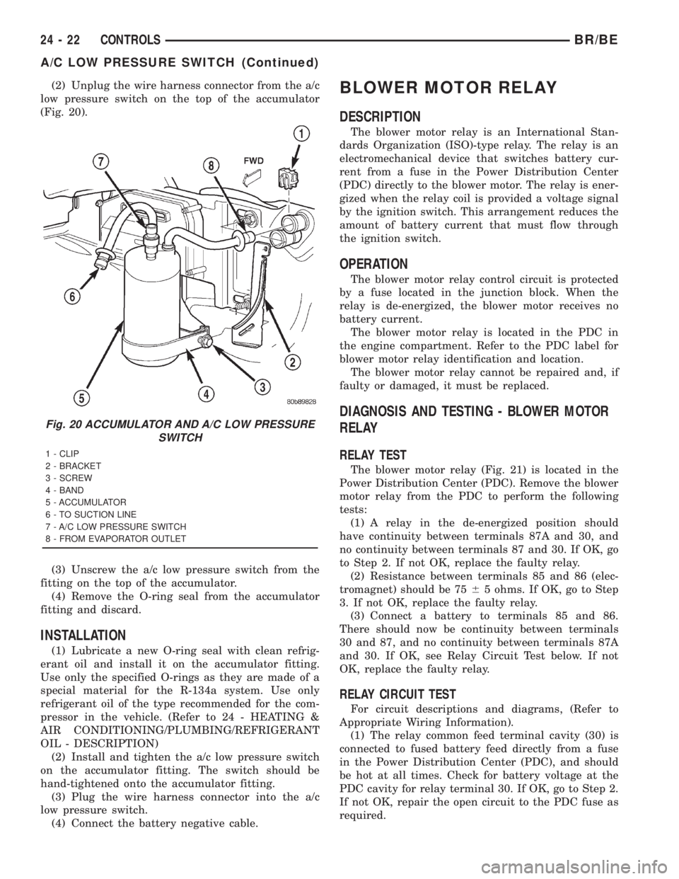
(2) Unplug the wire harness connector from the a/c
low pressure switch on the top of the accumulator
(Fig. 20).
(3) Unscrew the a/c low pressure switch from the
fitting on the top of the accumulator.
(4) Remove the O-ring seal from the accumulator
fitting and discard.
INSTALLATION
(1) Lubricate a new O-ring seal with clean refrig-
erant oil and install it on the accumulator fitting.
Use only the specified O-rings as they are made of a
special material for the R-134a system. Use only
refrigerant oil of the type recommended for the com-
pressor in the vehicle. (Refer to 24 - HEATING &
AIR CONDITIONING/PLUMBING/REFRIGERANT
OIL - DESCRIPTION)
(2) Install and tighten the a/c low pressure switch
on the accumulator fitting. The switch should be
hand-tightened onto the accumulator fitting.
(3) Plug the wire harness connector into the a/c
low pressure switch.
(4) Connect the battery negative cable.
BLOWER MOTOR RELAY
DESCRIPTION
The blower motor relay is an International Stan-
dards Organization (ISO)-type relay. The relay is an
electromechanical device that switches battery cur-
rent from a fuse in the Power Distribution Center
(PDC) directly to the blower motor. The relay is ener-
gized when the relay coil is provided a voltage signal
by the ignition switch. This arrangement reduces the
amount of battery current that must flow through
the ignition switch.
OPERATION
The blower motor relay control circuit is protected
by a fuse located in the junction block. When the
relay is de-energized, the blower motor receives no
battery current.
The blower motor relay is located in the PDC in
the engine compartment. Refer to the PDC label for
blower motor relay identification and location.
The blower motor relay cannot be repaired and, if
faulty or damaged, it must be replaced.
DIAGNOSIS AND TESTING - BLOWER MOTOR
RELAY
RELAY TEST
The blower motor relay (Fig. 21) is located in the
Power Distribution Center (PDC). Remove the blower
motor relay from the PDC to perform the following
tests:
(1) A relay in the de-energized position should
have continuity between terminals 87A and 30, and
no continuity between terminals 87 and 30. If OK, go
to Step 2. If not OK, replace the faulty relay.
(2) Resistance between terminals 85 and 86 (elec-
tromagnet) should be 7565 ohms. If OK, go to Step
3. If not OK, replace the faulty relay.
(3) Connect a battery to terminals 85 and 86.
There should now be continuity between terminals
30 and 87, and no continuity between terminals 87A
and 30. If OK, see Relay Circuit Test below. If not
OK, replace the faulty relay.
RELAY CIRCUIT TEST
For circuit descriptions and diagrams, (Refer to
Appropriate Wiring Information).
(1) The relay common feed terminal cavity (30) is
connected to fused battery feed directly from a fuse
in the Power Distribution Center (PDC), and should
be hot at all times. Check for battery voltage at the
PDC cavity for relay terminal 30. If OK, go to Step 2.
If not OK, repair the open circuit to the PDC fuse as
required.
Fig. 20 ACCUMULATOR AND A/C LOW PRESSURE
SWITCH
1 - CLIP
2 - BRACKET
3 - SCREW
4 - BAND
5 - ACCUMULATOR
6 - TO SUCTION LINE
7 - A/C LOW PRESSURE SWITCH
8 - FROM EVAPORATOR OUTLET
24 - 22 CONTROLSBR/BE
A/C LOW PRESSURE SWITCH (Continued)
Page 2754 of 2889
motor speeds, but can only be turned off by selecting
the Off position with the heater-only or a/c heater
control switch knob.
OPERATION
The blower motor switch directs the blower motor
ground path through the mode control switch to the
blower motor resistor, or directly to ground, as
required to achieve the selected blower motor speed.
The blower motor switch cannot be repaired and, if
faulty or damaged, the entire heater-only or a/c
heater control unit must be replaced. The blower
motor switch knob is serviced separately.
DIAGNOSIS AND TESTING - BLOWER MOTOR
SWITCH
For circuit descriptions and diagrams, (Refer to
Appropriate Wiring Information).
WARNING: ON VEHICLES EQUIPPED WITH AIR-
BAGS, DISABLE THE AIRBAG SYSTEM BEFORE
ATTEMPTING ANY STEERING WHEEL, STEERING
COLUMN, OR INSTRUMENT PANEL COMPONENT
DIAGNOSIS OR SERVICE. DISCONNECT AND ISO-
LATE THE BATTERY NEGATIVE (GROUND) CABLE,
THEN WAIT TWO MINUTES FOR THE AIRBAG SYS-
TEM CAPACITOR TO DISCHARGE BEFORE PER-
FORMING FURTHER DIAGNOSIS OR SERVICE. THIS
IS THE ONLY SURE WAY TO DISABLE THE AIRBAG
SYSTEM. FAILURE TO TAKE THE PROPER PRE-
CAUTIONS COULD RESULT IN AN ACCIDENTAL
AIRBAG DEPLOYMENT AND POSSIBLE PERSONAL
INJURY.
(1) Check for battery voltage at the fuse in the
Power Distribution Center (PDC). If OK, go to Step
2. If not OK, repair the shorted circuit or component
as required and replace the faulty fuse.
(2) Turn the ignition switch to the Off position.
Disconnect and isolate the battery negative cable.
Remove the a/c heater control from the instrument
panel. (Refer to 24 - HEATING & AIR CONDITION-
ING/CONTROLS/A/C HEATER CONTROL -
REMOVAL) Check for continuity between the ground
circuit cavity of the a/c heater control wire harness
connector and a good ground. There should be conti-
nuity. If OK, go to Step 3. If not OK, repair the open
circuit to ground as required.
(3) With the a/c heater control wire harness con-
nector unplugged, place the a/c heater mode control
switch knob in any position except the Off position.
Check for continuity between the ground circuit ter-
minal and each of the blower motor driver circuit ter-
minals of the a/c heater control as you move the
blower motor switch knob to each of the four speed
positions. There should be continuity at each drivercircuit terminal in only one blower motor switch
speed position. If OK, test and repair the blower
driver circuits between the a/c heater control connec-
tor and the blower motor resistor as required. If not
OK, replace the faulty a/c heater control unit.
REMOVAL
The blower motor switch cannot be repaired and, if
faulty or damaged, the entire heater-only or a/c
heater control unit must be replaced. (Refer to 24 -
HEATING & AIR CONDITIONING/CONTROLS/A/C
HEATER CONTROL - REMOVAL) The blower motor
switch knob is serviced separately.
BLEND DOOR ACTUATOR
REMOVAL
WARNING: ON VEHICLES EQUIPPED WITH AIR-
BAGS, DISABLE THE AIRBAG SYSTEM BEFORE
ATTEMPTING ANY STEERING WHEEL, STEERING
COLUMN, OR INSTRUMENT PANEL COMPONENT
DIAGNOSIS OR SERVICE. DISCONNECT AND ISO-
LATE THE BATTERY NEGATIVE (GROUND) CABLE,
THEN WAIT TWO MINUTES FOR THE AIRBAG SYS-
TEM CAPACITOR TO DISCHARGE BEFORE PER-
FORMING FURTHER DIAGNOSIS OR SERVICE. THIS
IS THE ONLY SURE WAY TO DISABLE THE AIRBAG
SYSTEM. FAILURE TO TAKE THE PROPER PRE-
CAUTIONS COULD RESULT IN AN ACCIDENTAL
AIRBAG DEPLOYMENT AND POSSIBLE PERSONAL
INJURY.
(1) Turn the ignition switch to the run position.
(2) Locate the temperature control knob in the mid
(12 o'clock) position.
(3) Turn the ignition switch to the off position.
(4) Disconnect and isolate the battery negative
cable.
(5) Remove the instrument panel from the vehicle.
Refer to Instrument Panel System for the procedures.
(6) Remove the HVAC housing from the vehicle.
(Refer to 24 - HEATING & AIR CONDITIONING/
DISTRIBUTION/HVAC HOUSING - REMOVAL)
(7) Unplug the wire harness connector from the
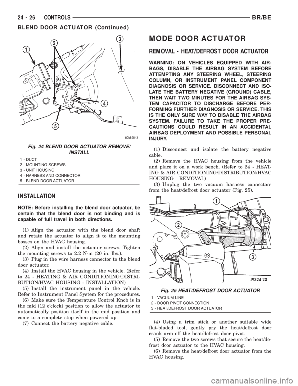
blend door actuator (Fig. 24).
(8) Remove the two mounting screws which secure
the actuator to the housing.
(9) Slide the blend door actuator off the blend door
shaft.
NOTE: A black plastic coupler may be attached to
the blend door shaft. Remove the coupler and
inspect for damage. Reinstall if there is no damage
found.
BR/BECONTROLS 24 - 25
BLOWER MOTOR SWITCH (Continued)
Page 2755 of 2889
INSTALLATION
NOTE: Before installing the blend door actuator, be
certain that the blend door is not binding and is
capable of full travel in both directions.
(1) Align the actuator with the blend door shaft
and rotate the actuator to align it to the mounting
bosses on the HVAC housing.
(2) Align and install the actuator screws. Tighten
the mounting screws to 2.2 N´m (20 in. lbs.).
(3) Plug in the wire harness connector to the blend
door actuator.
(4) Install the HVAC housing in the vehicle. (Refer
to 24 - HEATING & AIR CONDITIONING/DISTRI-
BUTION/HVAC HOUSING - INSTALLATION)
(5) Install the instrument panel in the vehicle.
Refer to Instrument Panel System for the procedures.
(6) Make sure the Temperature Control Knob is in
the mid (12 o'clock) position to allow the actuator to
automatically position itself in the mid position and
come to a complete stop when powered up.
(7) Connect the battery negative cable.
MODE DOOR ACTUATOR
REMOVAL - HEAT/DEFROST DOOR ACTUATOR
WARNING: ON VEHICLES EQUIPPED WITH AIR-
BAGS, DISABLE THE AIRBAG SYSTEM BEFORE
ATTEMPTING ANY STEERING WHEEL, STEERING
COLUMN, OR INSTRUMENT PANEL COMPONENT
DIAGNOSIS OR SERVICE. DISCONNECT AND ISO-
LATE THE BATTERY NEGATIVE (GROUND) CABLE,
THEN WAIT TWO MINUTES FOR THE AIRBAG SYS-
TEM CAPACITOR TO DISCHARGE BEFORE PER-
FORMING FURTHER DIAGNOSIS OR SERVICE. THIS
IS THE ONLY SURE WAY TO DISABLE THE AIRBAG
SYSTEM. FAILURE TO TAKE THE PROPER PRE-
CAUTIONS COULD RESULT IN AN ACCIDENTAL
AIRBAG DEPLOYMENT AND POSSIBLE PERSONAL
INJURY.
(1) Disconnect and isolate the battery negative
cable.
(2) Remove the HVAC housing from the vehicle
and place it on a work bench. (Refer to 24 - HEAT-
ING & AIR CONDITIONING/DISTRIBUTION/HVAC
HOUSING - REMOVAL)
(3) Unplug the two vacuum harness connectors
from the heat/defrost door actuator (Fig. 25).
(4) Using a trim stick or another suitable wide
flat-bladed tool, gently pry the heat/defrost door
crank arm off the heat/defrost door pivot.
(5) Remove the two screws that secure the heat/de-
frost door actuator to the HVAC housing.
(6) Remove the heat/defrost door actuator from the
HVAC housing.
Fig. 24 BLEND DOOR ACTUATOR REMOVE/
INSTALL
1 - DUCT
2 - MOUNTING SCREWS
3 - UNIT HOUSING
4 - HARNESS AND CONNECTOR
5 - BLEND DOOR ACTUATOR
Fig. 25 HEAT/DEFROST DOOR ACTUATOR
1 - VACUUM LINE
2 - DOOR PIVOT CONNECTION
3 - HEAT/DEFROST DOOR ACTUATOR
24 - 26 CONTROLSBR/BE
BLEND DOOR ACTUATOR (Continued)
Page 2756 of 2889
REMOVAL - PANEL/DEFROST DOOR
ACTUATOR
WARNING: ON VEHICLES EQUIPPED WITH AIRBAGS,
DISABLE THE AIRBAG SYSTEM BEFORE ATTEMPT-
ING ANY STEERING WHEEL, STEERING COLUMN, OR
INSTRUMENT PANEL COMPONENT DIAGNOSIS OR
SERVICE. DISCONNECT AND ISOLATE THE BATTERY
NEGATIVE (GROUND) CABLE, THEN WAIT TWO MIN-
UTES FOR THE AIRBAG SYSTEM CAPACITOR TO DIS-
CHARGE BEFORE PERFORMING FURTHER
DIAGNOSIS OR SERVICE. THIS IS THE ONLY SURE
WAY TO DISABLE THE AIRBAG SYSTEM. FAILURE TO
TAKE THE PROPER PRECAUTIONS COULD RESULT
IN AN ACCIDENTAL AIRBAG DEPLOYMENT AND POS-
SIBLE PERSONAL INJURY.
(1)Disconnect and isolate the battery negative cable.
(2) Remove the instrument panel assembly from
the vehicle. Refer to Instrument Panel System for the
procedures.
(3) Unplug the vacuum harness connector from the
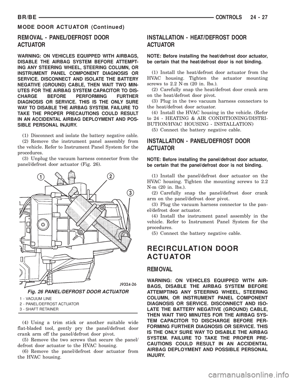
panel/defrost door actuator (Fig. 26).
(4) Using a trim stick or another suitable wide
flat-bladed tool, gently pry the panel/defrost door
crank arm off the panel/defrost door pivot.
(5) Remove the two screws that secure the panel/
defrost door actuator to the HVAC housing.
(6) Remove the panel/defrost door actuator from
the HVAC housing.
INSTALLATION - HEAT/DEFROST DOOR
ACTUATOR
NOTE: Before installing the heat/defrost door actuator,
be certain that the heat/defrost door is not binding.
(1) Install the heat/defrost door actuator from the
HVAC housing. Tighten the actuator mounting
screws to 2.2 N´m (20 in. lbs.).
(2) Carefully snap the heat/defrost door crank arm
on the heat/defrost door pivot.
(3) Plug in the two vacuum harness connectors to
the heat/defrost door actuator.
(4) Install the HVAC housing in the vehicle. (Refer
to 24 - HEATING & AIR CONDITIONING/DISTRI-
BUTION/HVAC HOUSING - INSTALLATION)
(5) Connect the battery negative cable.
INSTALLATION - PANEL/DEFROST DOOR
ACTUATOR
NOTE: Before installing the panel/defrost door actuator,
be certain that the panel/defrost door is not binding.
(1) Install the panel/defrost door actuator on the
HVAC housing. Tighten the mounting screws to 2.2
N´m (20 in. lbs.).
(2) Carefully snap the panel/defrost door crank
arm on the panel/defrost door pivot.
(3) Plug the vacuum harness connector to the pan-
el/defrost door actuator.
(4) Install the instrument panel assembly in the
vehicle. Refer to Instrument Panel System for the
procedures.
(5) Connect the battery negative cable.
RECIRCULATION DOOR
ACTUATOR
REMOVAL
WARNING: ON VEHICLES EQUIPPED WITH AIR-
BAGS, DISABLE THE AIRBAG SYSTEM BEFORE
ATTEMPTING ANY STEERING WHEEL, STEERING
COLUMN, OR INSTRUMENT PANEL COMPONENT
DIAGNOSIS OR SERVICE. DISCONNECT AND ISO-
LATE THE BATTERY NEGATIVE (GROUND) CABLE,
THEN WAIT TWO MINUTES FOR THE AIRBAG SYS-
TEM CAPACITOR TO DISCHARGE BEFORE PER-
FORMING FURTHER DIAGNOSIS OR SERVICE. THIS
IS THE ONLY SURE WAY TO DISABLE THE AIRBAG
SYSTEM. FAILURE TO TAKE THE PROPER PRE-
CAUTIONS COULD RESULT IN AN ACCIDENTAL
AIRBAG DEPLOYMENT AND POSSIBLE PERSONAL
INJURY.
Fig. 26 PANEL/DEFROST DOOR ACTUATOR
1 - VACUUM LINE
2 - PANEL/DEFROST ACTUATOR
3 - SHAFT RETAINER
BR/BECONTROLS 24 - 27
MODE DOOR ACTUATOR (Continued)
Page 2764 of 2889
(3) Disengage the demister tubes from each end of
the main demister duct.
(4) Remove the defroster and demister duct unit
from the instrument panel.
REMOVAL - DEFROSTER AND DEMISTER
DUCT ADAPTER
(1) Roll the instrument panel assembly down, but
do not remove it from the vehicle. Refer to Instru-
ment Panel System for the procedures.
(2)
Using a trim stick or another suitable wide flat-
bladed tool, gently pry at the perimeter edges of the
defroster and demister duct adapter to release the snap
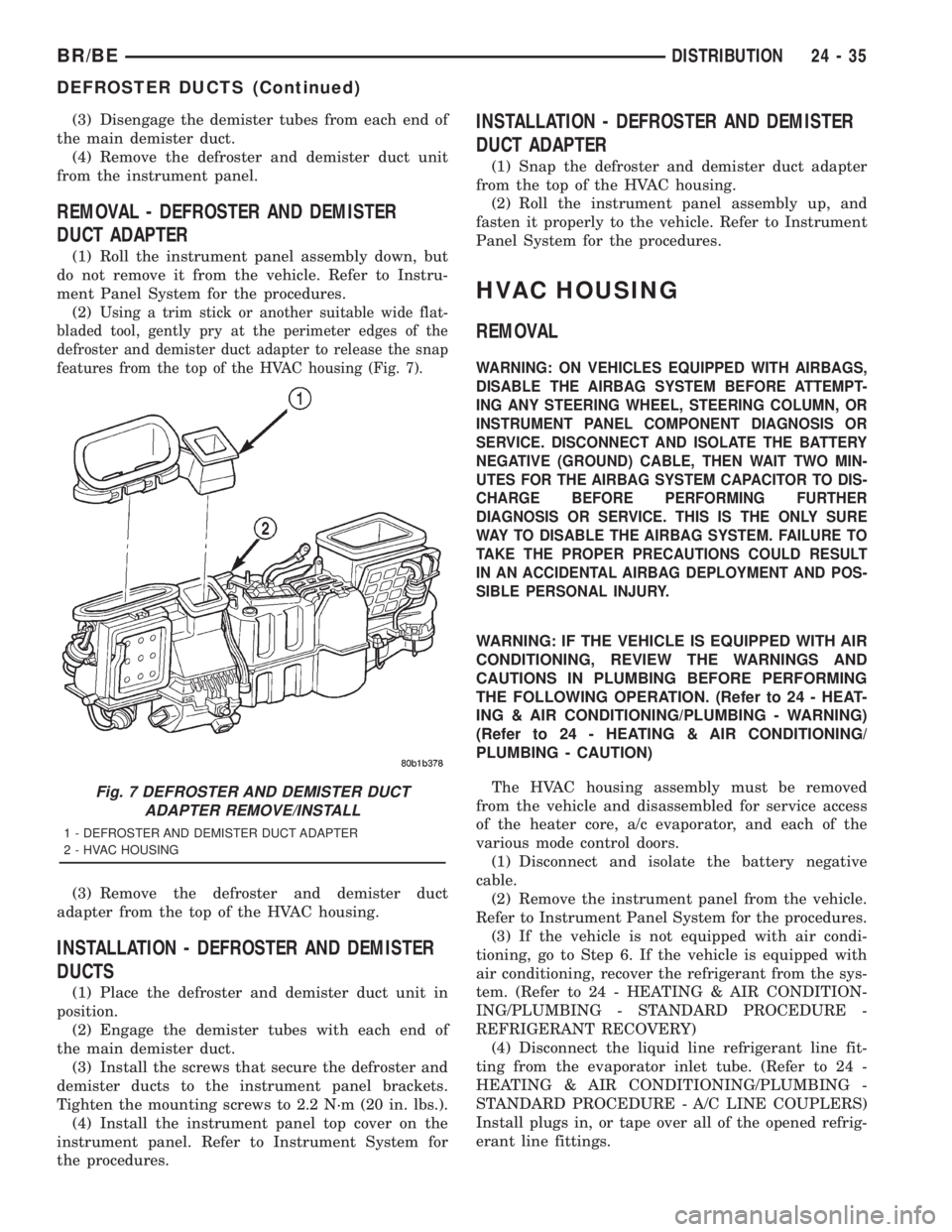
features from the top of the HVAC housing (Fig. 7).
(3) Remove the defroster and demister duct
adapter from the top of the HVAC housing.
INSTALLATION - DEFROSTER AND DEMISTER
DUCTS
(1) Place the defroster and demister duct unit in
position.
(2) Engage the demister tubes with each end of
the main demister duct.
(3) Install the screws that secure the defroster and
demister ducts to the instrument panel brackets.
Tighten the mounting screws to 2.2 N´m (20 in. lbs.).
(4) Install the instrument panel top cover on the
instrument panel. Refer to Instrument System for
the procedures.
INSTALLATION - DEFROSTER AND DEMISTER
DUCT ADAPTER
(1) Snap the defroster and demister duct adapter
from the top of the HVAC housing.
(2) Roll the instrument panel assembly up, and
fasten it properly to the vehicle. Refer to Instrument
Panel System for the procedures.
HVAC HOUSING
REMOVAL
WARNING: ON VEHICLES EQUIPPED WITH AIRBAGS,
DISABLE THE AIRBAG SYSTEM BEFORE ATTEMPT-
ING ANY STEERING WHEEL, STEERING COLUMN, OR
INSTRUMENT PANEL COMPONENT DIAGNOSIS OR
SERVICE. DISCONNECT AND ISOLATE THE BATTERY
NEGATIVE (GROUND) CABLE, THEN WAIT TWO MIN-
UTES FOR THE AIRBAG SYSTEM CAPACITOR TO DIS-
CHARGE BEFORE PERFORMING FURTHER
DIAGNOSIS OR SERVICE. THIS IS THE ONLY SURE
WAY TO DISABLE THE AIRBAG SYSTEM. FAILURE TO
TAKE THE PROPER PRECAUTIONS COULD RESULT
IN AN ACCIDENTAL AIRBAG DEPLOYMENT AND POS-
SIBLE PERSONAL INJURY.
WARNING: IF THE VEHICLE IS EQUIPPED WITH AIR
CONDITIONING, REVIEW THE WARNINGS AND
CAUTIONS IN PLUMBING BEFORE PERFORMING
THE FOLLOWING OPERATION. (Refer to 24 - HEAT-
ING & AIR CONDITIONING/PLUMBING - WARNING)
(Refer to 24 - HEATING & AIR CONDITIONING/
PLUMBING - CAUTION)
The HVAC housing assembly must be removed
from the vehicle and disassembled for service access
of the heater core, a/c evaporator, and each of the
various mode control doors.
(1) Disconnect and isolate the battery negative
cable.
(2) Remove the instrument panel from the vehicle.
Refer to Instrument Panel System for the procedures.
(3) If the vehicle is not equipped with air condi-
tioning, go to Step 6. If the vehicle is equipped with
air conditioning, recover the refrigerant from the sys-
tem. (Refer to 24 - HEATING & AIR CONDITION-
ING/PLUMBING - STANDARD PROCEDURE -
REFRIGERANT RECOVERY)
(4) Disconnect the liquid line refrigerant line fit-
ting from the evaporator inlet tube. (Refer to 24 -
HEATING & AIR CONDITIONING/PLUMBING -
STANDARD PROCEDURE - A/C LINE COUPLERS)
Install plugs in, or tape over all of the opened refrig-
erant line fittings.
Fig. 7 DEFROSTER AND DEMISTER DUCT
ADAPTER REMOVE/INSTALL
1 - DEFROSTER AND DEMISTER DUCT ADAPTER
2 - HVAC HOUSING
BR/BEDISTRIBUTION 24 - 35
DEFROSTER DUCTS (Continued)