2001 DODGE RAM wait to start light
[x] Cancel search: wait to start lightPage 300 of 2889
(6) Position adjuster lever return spring on pivot.
(7) Install adjuster lever.
(8) Attach adjuster cable to adjuster lever. Be sure
cable is properly routed.
(9) Adjust brake shoes to drum with brake gauge.
MASTER CYLINDER
DESCRIPTION
A two-piece master cylinder is used on all models.
The cylinder body containing the primary and sec-
ondary pistons is made of aluminum. The removable
fluid reservoir is made of nylon reinforced with glass
fiber. The reservoir stores reserve brake fluid for the
hydraulic brake circuits. The reservoir is the only
serviceable component.
The fluid compartments of the nylon reservoir are
interconnected to permit fluid level equalization.
However, the equalization feature does not affect cir-
cuit separation in the event of a front or rear brake
malfunction. The reservoir compartments will retain
enough fluid to operate the functioning hydraulic cir-
cuit.
Care must be exercised when removing/installing
the master cylinder connecting lines. The threads in
the cylinder fluid ports can be damaged if care is not
exercised. Start all brake line fittings by hand to
avoid cross threading.
The cylinder reservoir can be replaced when neces-
sary. However, the aluminum body section of the
master cylinder is not a repairable component.
NOTE: If diagnosis indicates that an internal mal-
function has occurred, the aluminum body section
must be replaced as an assembly.
OPERATION
The master cylinder bore contains a primary and
secondary piston. The primary piston supplies
hydraulic pressure to the front brakes. The secondary
piston supplies hydraulic pressure to the rear brakes.
DIAGNOSIS AND TESTING - MASTER
CYLINDER/POWER BOOSTER
(1) Start engine and check booster vacuum hose
connections. A hissing noise indicates vacuum leak.
Correct any vacuum leak before proceeding.
(2) Stop engine and shift transmission into Neu-
tral.
(3) Pump brake pedal until all vacuum reserve in
booster is depleted.
(4) Press and hold brake pedal under light foot
pressure. The pedal should hold firm, if the pedal
falls away master cylinder is faulty (internal leak-
age).
(5) Start engine and note pedal action. It should
fall away slightly under light foot pressure then hold
firm. If no pedal action is discernible, power booster,
vacuum supply, or vacuum check valve is faulty. Pro-
ceed to the POWER BOOSTER VACUUM TEST.
(6) If the POWER BOOSTER VACUUM TEST
passes, rebuild booster vacuum reserve as follows:
Release brake pedal. Increase engine speed to 1500
rpm, close the throttle and immediately turn off igni-
tion to stop engine.
(7) Wait a minimum of 90 seconds and try brake
action again. Booster should provide two or more vac-
uum assisted pedal applications. If vacuum assist is
not provided, booster is faulty.
POWER BOOSTER VACUUM TEST
(1) Connect vacuum gauge to booster check valve
with short length of hose and T-fitting (Fig. 54).
(2) Start and run engine at curb idle speed for one
minute.
(3) Observe the vacuum supply. If vacuum supply
is not adequate, repair vacuum supply.
(4) Clamp hose shut between vacuum source and
check valve.
(5) Stop engine and observe vacuum gauge.
(6) If vacuum drops more than one inch HG (33
millibars) within 15 seconds, booster diaphragm or
check valve is faulty.
POWER BOOSTER CHECK VALVE TEST
(1) Disconnect vacuum hose from check valve.
(2) Remove check valve and valve seal from
booster.
(3) Use a hand operated vacuum pump for test.
(4) Apply 15-20 inches vacuum at large end of
check valve (Fig. 55).
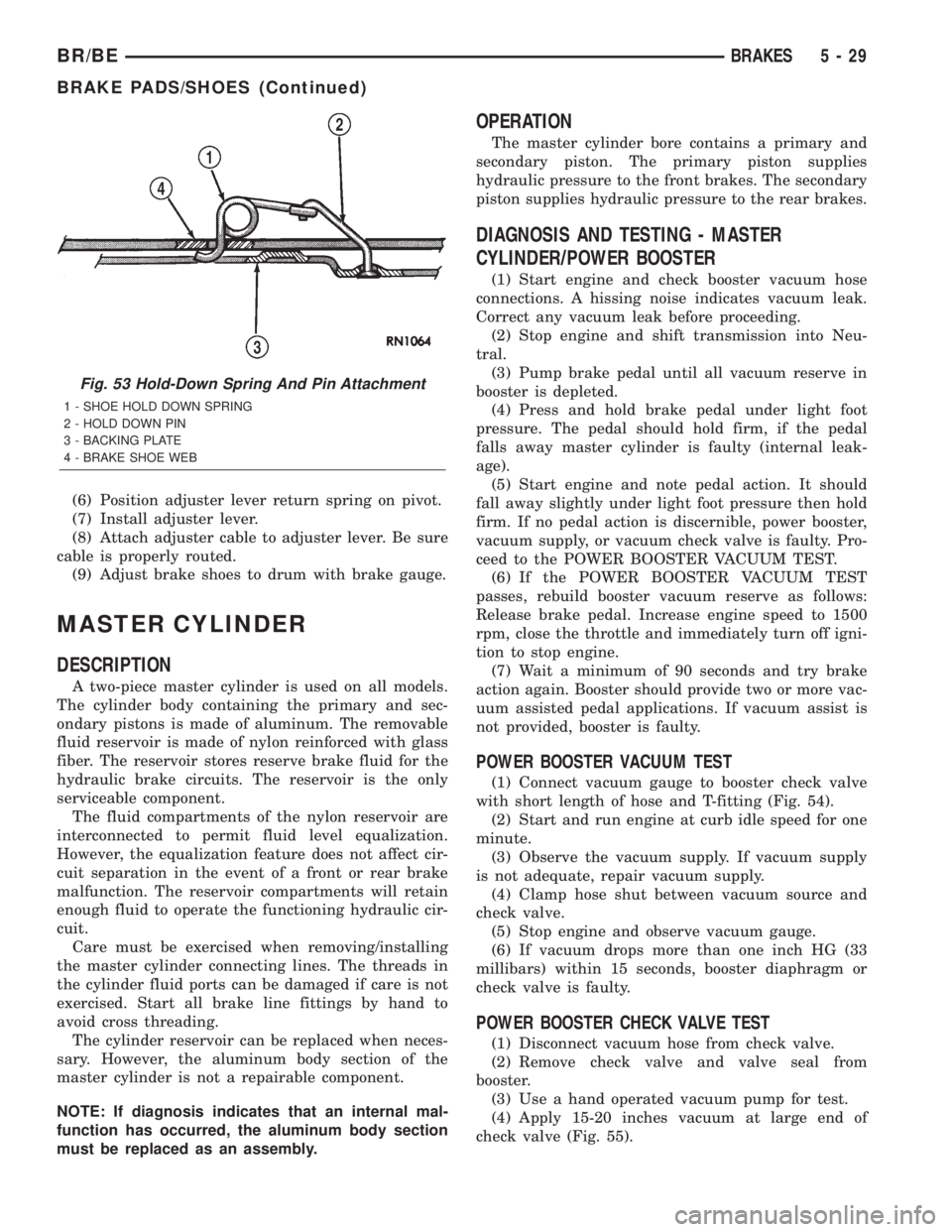
Fig. 53 Hold-Down Spring And Pin Attachment
1 - SHOE HOLD DOWN SPRING
2 - HOLD DOWN PIN
3 - BACKING PLATE
4 - BRAKE SHOE WEB
BR/BEBRAKES 5 - 29
BRAKE PADS/SHOES (Continued)
Page 521 of 2889

OPERATION
The heated seat module receives fused battery cur-
rent through the energized heated seat relay in the
Junction Block (JB) only when the engine is running.
The heated seat switches receive battery current
through a fused ignition switch output (run) circuit
only when the ignition switch is in the On position.
The heated seat module shares a common ground cir-
cuit with each of the heated seat elements. The
heated seat elements will only operate when the sur-
face temperature of the seat cushion cover at the
heated seat sensors is below the designed tempera-
ture set points of the system.
The heated seat module will automatically turn off
the heated seat elements if it detects a short in the
heated seat element circuit or a heated seat sensor
value that is out of range. The heated seat system
will also be turned off automatically whenever the
ignition switch is turned to any position except On or
if the engine quits running. If the ignition switch is
turned to the Off position or if the engine quits run-
ning while a heated seat is turned ON, the heated
seat will remain Off after the engine is restarted
until a heated seat switch is depressed again.
The heated seat module monitors inputs from the
heated seat sensors and the heated seat switches. In
response to these inputs the heated seat module uses
its internal programming to control outputs to the
heated seat elements in both front seats and to con-
trol the heated seat LED indicator lamps located in
both of the heated seat switches. The heated seat
module is also programmed to provide a self-diagnos-
tic capability. When the module detects certain fail-
ures within the heated seat system, it will provide a
visual indication of the failure by flashing the indica-
tor lamps in the heated seat switches.
DIAGNOSIS & TESTING - HEATED SEAT
SYSTEM
SELF-DIAGNOSIS
The heated seat system is capable of performing
some self-diagnostics. The following table depicts the
various failure modes which will be reported to the
vehicle operator or technician by flashing the individ-
ual heated seat switch Light Emitting Diode (LED)
indicator lamps. See the Heated Seat System Self-Di-
agnosis table for the diagnostic routines. The driver
side heated seat switch indicator lamps will flash if a
failure occurs in the driver side heated seat, and the
passenger side heated seat switch indicator lamps
will flash for a passenger side heated seat failure. If
a monitored heated seat system failure occurs, the
switch indicator lamps will flash at a pulse rate of
about one-half second on, followed by about one-half
second off for a duration of about one minute afterthe switch for the faulty heated seat is depressed in
either the Low or High direction. This process will
repeat every time the faulty heated seat switch is
actuated until the problem has been corrected.
Heated Seat System Self-Diagnosis
Monitored FailureSwitch High
Indicator LampSwitch Low
Indicator Lamp
Heated Seat
Element ShortedFlashing Flashing
Heated Seat
Element OpenFlashing Off
Heated Seat
Sensor Value Out
of RangeOff Flashing
TESTING
Refer toPower Seatin the index of this service
manual for the location of complete heated seat sys-
tem wiring diagrams. Before testing the individual
components in the heated seat system, perform the
following preliminary checks:
WARNING: ON VEHICLES EQUIPPED WITH AIR-
BAGS, DISABLE THE AIRBAG SYSTEM BEFORE
ATTEMPTING ANY STEERING WHEEL, STEERING
COLUMN, OR INSTRUMENT PANEL COMPONENT
DIAGNOSIS OR SERVICE. DISCONNECT AND ISO-
LATE THE BATTERY NEGATIVE (GROUND) CABLE,
THEN WAIT TWO MINUTES FOR THE AIRBAG SYS-
TEM CAPACITOR TO DISCHARGE BEFORE PER-
FORMING FURTHER DIAGNOSIS OR SERVICE. THIS
IS THE ONLY SURE WAY TO DISABLE THE AIRBAG
SYSTEM. FAILURE TO TAKE THE PROPER PRE-
CAUTIONS COULD RESULT IN ACCIDENTAL AIR-
BAG DEPLOYMENT AND POSSIBLE PERSONAL
INJURY.
²If the heated seat switch back lighting and the
cluster illumination lamps do not illuminate with the
headlamps or park lamps turned On, refer toInstru-
ment Clusterin the index of this service manual for
the location of the proper cluster illumination lamps
diagnosis and testing procedures. If the heated seat
switch back lighting does not illuminate, but the
cluster illumination lamps do illuminate with the
headlamps or park lamps turned On, refer to
Heated Seat Switchin this section for the location
of the proper heated seat switch diagnosis and test-
ing procedure.
²If a single indicator lamp for one heated seat
switch does not operate and the heated seat elements
do heat, refer toHeated Seat Switchin this section
for the location of the proper heated seat switch diag-
nosis and testing procedure.
8G - 6 HEATED SEAT SYSTEMBR/BE
HEATED SEAT SYSTEM (Continued)
Page 562 of 2889
²Check Gauges Indicator
²Cruise Indicator (Odometer VFD)
²Four-Wheel Drive Indicator
²High Beam Indicator
²Low Fuel Indicator
²Washer Fluid Indicator
²Malfunction Indicator Lamp (MIL)
²Overdrive-Off Indicator
²Seatbelt Indicator
²Service Reminder Indicator (SRI)
²Transmission Overtemp Indicator
²Turn Signal (Right and Left) Indicators
²Upshift Indicator
²Wait-To-Start Indicator (Diesel Only)
²Water-In-Fuel Indicator (Diesel Only)
Some of these indicators are either programmable
or automatically configured when the EMIC is con-
nected to the vehicle electrical system. This feature
allows those indicators to be activated or deactivated
for compatibility with certain optional equipment.
The EMIC also includes a provision for mounting the
automatic transmission gear selector indicator in the
lower right corner of the cluster. The spring-loaded,
cable driven, mechanical gear selector indicator gives
an indication of the transmission gear that has been
selected with the automatic transmission gear selec-
tor lever. The gear selector indicator pointer is easily
visible through an opening provided in the front of
the cluster overlay, and is also lighted by the cluster
illumination lamps for visibility at night. Models
equipped with a manual transmission have a block-
out plate installed in place of the gear selector indi-
cator.
Cluster illumination is accomplished by adjustable
incandescent back lighting, which illuminates the
gauges for visibility when the exterior lighting is
turned on. The EMIC high beam indicator, turn sig-
nal indicators, and wait-to-start indicator are also
illuminated by dedicated incandescent bulbs. The
remaining indicators in the EMIC are each illumi-
nated by a dedicated Light Emitting Diode (LED)
that is soldered onto the electronic circuit board.
Each of the incandescent bulbs is secured by an inte-
gral bulb holder to the electronic circuit board from
the back of the cluster housing.
Hard wired circuitry connects the EMIC to the
electrical system of the vehicle. These hard wired cir-
cuits are integral to several wire harnesses, which
are routed throughout the vehicle and retained by
many different methods. These circuits may be con-
nected to each other, to the vehicle electrical system
and to the EMIC through the use of a combination of
soldered splices, splice block connectors, and many
different types of wire harness terminal connectors
and insulators. Refer to the appropriate wiring infor-
mation. The wiring information includes wiring dia-grams, proper wire and connector repair procedures,
further details on wire harness routing and reten-
tion, as well as pin-out and location views for the
various wire harness connectors, splices and grounds.
The EMIC modules for this model are serviced only
as complete units. The EMIC module cannot be
adjusted or repaired. If a gauge, an LED indicator,
the VFD, the electronic circuit board, the circuit
board hardware, the cluster overlay, or the EMIC
housing are damaged or faulty, the entire EMIC mod-
ule must be replaced. The cluster lens and hood unit,
the rear cluster housing cover, the automatic trans-
mission gear selector indicator, and the incandescent
lamp bulbs with holders are available for individual
service replacement.
OPERATION
The ElectroMechanical Instrument Cluster (EMIC)
is designed to allow the vehicle operator to monitor
the conditions of many of the vehicle components and
operating systems. The gauges and indicators in the
EMIC provide valuable information about the various
standard and optional powertrains, fuel and emis-
sions systems, cooling systems, lighting systems,
safety systems and many other convenience items.
The EMIC is installed in the instrument panel so
that all of these monitors can be easily viewed by the
vehicle operator when driving, while still allowing
relative ease of access for service. The microproces-
sor-based EMIC hardware and software uses various
inputs to control the gauges and indicators visible on
the face of the cluster. Some of these inputs are hard
wired, but most are in the form of electronic mes-
sages that are transmitted by other electronic mod-
ules over the Chrysler Collision Detection (CCD) data
bus network. (Refer to 8 - ELECTRICAL/ELEC-
TRONIC CONTROL MODULES/COMMUNICATION
- OPERATION).
The EMIC microprocessor smooths the input data
using algorithms to provide gauge readings that are
accurate, stable and responsive to operating condi-
tions. These algorithms are designed to provide
gauge readings during normal operation that are con-
sistent with customer expectations. However, when
abnormal conditions exist, such as low/high battery
voltage, low oil pressure, or high coolant tempera-
ture, the algorithm drives the gauge pointer to an
extreme position and the microprocessor turns on the
Check Gauges indicator to provide a distinct visual
indication of a problem to the vehicle operator. The
instrument cluster circuitry may also generate a
hard wired chime tone request to the Central Timer
Module (CTM) when it monitors certain conditions or
inputs, in order to provide the vehicle operator with
an audible alert.
BR/BEINSTRUMENT CLUSTER 8J - 3
INSTRUMENT CLUSTER (Continued)
Page 564 of 2889
The VFD is diagnosed using the EMIC self-diag-
nostic actuator test. (Refer to 8 - ELECTRICAL/IN-
STRUMENT CLUSTER - DIAGNOSIS AND
TESTING). Proper testing of the CCD data bus and
the data bus message inputs to the EMIC that con-
trol some of the VFD functions requires the use of a
DRBIIItscan tool. Refer to the appropriate diagnos-
tic information. Specific operation details for the
odometer and trip odometer functions of the VFD
may be found elsewhere in this service manual.
INDICATORS
Indicators are located in various positions within
the EMIC and are all connected to the EMIC circuit
board. The four-wheel drive indicator, high beam
indicator, washer fluid indicator, turn signal indica-
tors, and wait-to-start indicator are hard wired. The
brake indicator is controlled by CCD data bus mes-
sages from the Controller Anti-lock Brake (CAB) and
the hard wired park brake switch input to the EMIC.
The seatbelt indicator is controlled by the EMIC pro-
gramming, CCD data bus messages from the Airbag
Control Module (ACM), and the hard wired seat belt
switch input to the EMIC. The Malfunction Indicator
Lamp (MIL) is normally controlled by CCD data bus
messages from the Powertrain Control Module
(PCM); however, if the EMIC loses CCD data bus
communications, the EMIC circuitry will automati-
cally turn the MIL on, and flash the odometer VFD
on and off repeatedly until CCD data bus communi-
cation is restored. The EMIC uses CCD data bus
messages from the Powertrain Control Module
(PCM), the diesel engine only Engine Control Module
(ECM), the ACM, and the CAB to control all of the
remaining indicators. Different indicators are con-
trolled by different strategies; some receive fused
ignition switch output from the EMIC circuitry clus-
ter and have a switched ground, while others are
grounded through the EMIC circuitry and have a
switched battery feed.
In addition, certain indicators in this instrument
cluster are programmable or configurable. This fea-
ture allows the programmable indicators to be acti-
vated or deactivated with a DRBIIItscan tool, while
the configurable indicators will be automatically
enabled or disabled by the EMIC circuitry for com-
patibility with certain optional equipment. The only
programmable indicator for this model is the upshift
indicator. The cruise indicator, four-wheel drive indi-
cator, overdrive-off indicator, service reminder indica-
tor, and the transmission overtemp indicator are
automatically configured, either electronically or
mechanically.The hard wired indicators are diagnosed using con-
ventional diagnostic methods. The EMIC and CCD
bus message controlled indicator lamps are diagnosed
using the EMIC self-diagnostic actuator test. (Refer
to 8 - ELECTRICAL/INSTRUMENT CLUSTER -
DIAGNOSIS AND TESTING). Proper testing of the
CCD data bus and the data bus message inputs to
the EMIC that control each indicator lamp require
the use of a DRBIIItscan tool. Refer to the appro-
priate diagnostic information. Specific operation
details for each indicator may be found elsewhere in
this service manual.
CLUSTER ILLUMINATION
The EMIC has several illumination lamps that are
illuminated when the exterior lighting is turned on
with the headlamp switch. The illumination bright-
ness of these lamps is adjusted by the panel lamps
dimmer rheostat when the headlamp switch thumb-
wheel is rotated (down to dim, up to brighten). The
illumination lamps receive battery current through
the panel lamps dimmer rheostat and a fuse in the
JB on a fused panel lamps dimmer switch signal cir-
cuit. The illumination lamps are grounded at all
times.
In addition, an analog/digital (A/D) converter in
the EMIC converts the analog panel lamps dimmer
rheostat input from the headlamp switch to a digital
dimming level signal for controlling the lighting level
of the VFD. The EMIC also broadcasts this digital
dimming information as a message over the CCD
data bus for use by the Compass Mini-Trip Computer
(CMTC) in synchronizing the lighting level of its
VFD with that of the EMIC. The headlamp switch
thumbwheel also has a Parade position to provide a
parade mode. The EMIC monitors the request for
this mode through a hard wired day brightness sense
circuit input from the headlamp switch. In this mode,
the EMIC will override the selected panel dimmer
switch signal and send a message over the CCD data
bus to illuminate all vacuum fluorescent displays at
full brightness for easier visibility when driving in
daylight with the exterior lighting turned on. The
parade mode has no effect on the incandescent bulb
illumination intensity.
The hard wired cluster illumination lamps are
diagnosed using conventional diagnostic methods.
Proper testing of the VFD dimming level and the
CCD data bus dimming level message functions
requires the use of a DRBIIItscan tool. Refer to the
appropriate diagnostic information.
BR/BEINSTRUMENT CLUSTER 8J - 5
INSTRUMENT CLUSTER (Continued)
Page 566 of 2889
(7) Turn the ignition switch to the Off position.
Disconnect and isolate the battery negative cable.
Reinstall the instrument cluster. Reconnect the bat-
tery negative cable. Turn the ignition switch to the
On position. Set the park brake. The brake indicator
in the instrument cluster should light. If OK, go to
Step 8. If not OK, go to Step 9.
(8) Turn the ignition switch to the Off position.
Turn on the park lamps and adjust the panel lamps
dimmer thumbwheel in the headlamp switch to the
full bright position. The cluster illumination lamps
should light. If OK, go to Step 10. If not OK, repair
the open ground circuit (Z3) between the instrument
cluster and ground (G201) as required.
(9) Turn the ignition switch to the Off position.
Disconnect and isolate the battery negative cable.
Remove the instrument cluster. Connect the battery
negative cable. Turn the ignition switch to the On
position. Check for battery voltage at the fused igni-
tion switch output (st-run) circuit cavity of the
instrument panel wire harness connector (Connector
C1). If OK, refer to ACTUATOR TEST . If not OK,
repair the open fused ignition switch output (st-run)
circuit between the instrument cluster and the JB as
required.
(10) Disconnect and isolate the battery negative
cable. Remove the instrument cluster. Check for con-
tinuity between the ground circuit (Z2) cavity of the
instrument panel wire harness connector (Connector
C1) and a good ground. There should be continuity. If
OK, refer to ACTUATOR TEST . If not OK, repair
the open ground circuit to ground (G200) as required.
ACTUATOR TEST
WARNING: ON VEHICLES EQUIPPED WITH AIR-
BAGS, DISABLE THE AIRBAG SYSTEM BEFORE
ATTEMPTING ANY STEERING WHEEL, STEERING
COLUMN, OR INSTRUMENT PANEL COMPONENT
DIAGNOSIS OR SERVICE. DISCONNECT AND ISO-
LATE THE BATTERY NEGATIVE (GROUND) CABLE,
THEN WAIT TWO MINUTES FOR THE AIRBAG SYS-
TEM CAPACITOR TO DISCHARGE BEFORE PER-
FORMING FURTHER DIAGNOSIS OR SERVICE. THIS
IS THE ONLY SURE WAY TO DISABLE THE AIRBAG
SYSTEM. FAILURE TO TAKE THE PROPER PRE-CAUTIONS COULD RESULT IN ACCIDENTAL AIR-
BAG DEPLOYMENT AND POSSIBLE PERSONAL
INJURY.
The instrument cluster actuator test will put the
instrument cluster into its self-diagnostic mode. In
this mode the instrument cluster can perform a self-
diagnostic test that will confirm that the instrument
cluster circuitry, the gauges, and the CCD data bus
message-controlled indicators are capable of operat-
ing as designed. During the actuator test the instru-
ment cluster circuitry position each of the gauge
needles at various calibration points, illuminate each
of the segments in the Vacuum-Fluorescent Display
(VFD), and turn all of the CCD data bus message-
controlled indicators on and off.
Successful completion of the actuator test will con-
firm that the instrument cluster is operational. How-
ever, there may still be a problem with the CCD data
bus, the Powertrain Control Module (PCM), the
Engine Control Module (ECM), the Airbag Control
Module (ACM), the Controller Anti-lock Brake (CAB),
or the inputs to one of these electronic control mod-
ules. Use a DRBIIItscan tool to diagnose these com-
ponents. Refer to the appropriate diagnostic
information.
(1) Begin the test with the ignition switch in the
Off position.
(2) Depress the odometer/trip odometer switch but-
ton.
(3) While still holding the odometer/trip odometer
switch button depressed, turn the ignition switch to
the On position, but do not start the engine.
(4) Keep the odometer/trip odometer switch button
depressed for about ten seconds, untilCHEC
appears in the odometer display, then release the
odometer/trip odometer switch button.
(5) A series of three-digit numeric failure messages
may appear in the odometer display, depending upon
the failure mode. If a failure message appears, refer
to the Instrument Cluster Failure Message chart for
the description and proper correction. If no failure
message appears, the actuator test will proceed as
described in Step 6.
BR/BEINSTRUMENT CLUSTER 8J - 7
INSTRUMENT CLUSTER (Continued)
Page 567 of 2889

INSTRUMENT CLUSTER FAILURE MESSAGE
Message Description Correction
110 A failure has been identified in the cluster
CPU, RAM, or EEPROM.1. Replace the faulty cluster.
900 The CCD data bus is not operational. 1. Check the CCD data bus connections at the
cluster.
2. Check the cluster fuses.
3. Check the CCD data bus bias.
4. Check the CCD data bus voltage.
5. Check the CCD data bus terminations.
920 The cluster is not receiving a vehicle speed
message from the PCM.1. Check the PCM software level and reflash if
required.
2. Use a DRBIIITscan tool to verify that the
vehicle speed message is being sent by the
PCM.
921 The cluster is not receiving a distance pulse
message from the PCM.1. Check the PCM software level and reflash if
required.
2. Use a DRBIIITscan tool to verify that the
distance pulse message is being sent by the
PCM.
940 The cluster is not receiving an airbag lamp-on
message from the ACM.1. Check the CCD data bus connections at the
ACM.
2. Check the ACM fuse.
950 The cluster is not receiving an ABS lamp-on
message from the CAB.1. Check the CCD data bus connections at the
CAB.
2. Check the CAB fuse.
999 An error has been discovered. 1. Record the failure message.
2. Depress the trip odometer reset button to
continue the Self-Diagnostic Test.
(6) The instrument cluster will begin the Vacuum
Fluorescent Display (VFD) walking segment test.
This test will require the operator to visually inspect
each VFD segment as it is displayed to determine a
pass or fail condition. First, all of the segments will
be illuminated at once; then, each individual segment
of the VFD will be illuminated in sequence. If any
segment in the display fails to illuminate, repeat the
test to confirm the failure. If the failure is confirmed,
replace the faulty instrument cluster. Following com-
pletion of the VFD walking segment test, the actua-
tor test will proceed as described in Step 7.
(7) The instrument cluster will perform a bulb
check of each indicator that the instrument cluster
circuitry controls. If the wait-to-start indicator does
not illuminate during this test, the instrument clus-
ter should be removed. However, check that the
incandescent bulb is not faulty and that the bulb
holder is properly installed on the instrument cluster
electronic circuit board before considering instrument
cluster replacement. If the bulb and bulb holder
check OK, replace the faulty instrument cluster.
Each of the remaining instrument cluster circuitrycontrolled indicators except the cruise indicator are
illuminated by a Light Emitting Diode (LED). If an
LED or the cruise indicator in the VFD, fails to illu-
minate during this test, the instrument cluster must
be replaced. Following the bulb check test, the actua-
tor test will proceed as described in Step 8.
(8) The instrument cluster will perform a gauge
actuator test. In this test the instrument cluster cir-
cuitry positions each of the gauge needles at three
different calibration points, then returns the gauge
needles to their relaxed positions. If an individual
gauge does not respond properly, or does not respond
at all during the gauge actuator test, the instrument
cluster should be removed. However, check that the
gauge terminal pins are properly inserted through
the spring-clip terminal pin receptacles on the instru-
ment cluster electronic circuit board before consider-
ing instrument cluster replacement. If the gauge
terminal connections are OK, replace the faulty
instrument cluster.
(9) The actuator test is now completed. The instru-
ment cluster will automatically exit the self-diagnos-
tic mode and return to normal operation at the
8J - 8 INSTRUMENT CLUSTERBR/BE
INSTRUMENT CLUSTER (Continued)
Page 573 of 2889
INSTALLATION
WARNING: ON VEHICLES EQUIPPED WITH AIR-
BAGS, DISABLE THE AIRBAG SYSTEM BEFORE
ATTEMPTING ANY STEERING WHEEL, STEERING
COLUMN, OR INSTRUMENT PANEL COMPONENT
DIAGNOSIS OR SERVICE. DISCONNECT AND ISO-
LATE THE BATTERY NEGATIVE (GROUND) CABLE,
THEN WAIT TWO MINUTES FOR THE AIRBAG SYS-
TEM CAPACITOR TO DISCHARGE BEFORE PER-
FORMING FURTHER DIAGNOSIS OR SERVICE. THIS
IS THE ONLY SURE WAY TO DISABLE THE AIRBAG
SYSTEM. FAILURE TO TAKE THE PROPER PRE-
CAUTIONS COULD RESULT IN ACCIDENTAL AIR-
BAG DEPLOYMENT AND POSSIBLE PERSONAL
INJURY.
(1) Position the instrument cluster to the instru-
ment panel.
(2) If the vehicle is equipped with an automatic
transmission, position the gear selector indicator onto
the back of the cluster housing (Fig. 3).
(3) If the vehicle is equipped with an automatic
transmission, install and tighten the two screws that
secure the gear selector indicator mechanism to the
back of the cluster housing. Tighten the screws to 2.2
N´m (20 in. lbs.).
(4) Align the instrument cluster with the cluster
opening in the instrument panel and push the cluster
firmly and evenly into place. The instrument panel
wire harness has two self-docking connectors that
will be automatically aligned with, and connected to
the instrument cluster connector receptacles when
the cluster is properly installed in the instrument
panel.
(5) Install and tighten the four screws that secure
the instrument cluster to the instrument panel (Fig.
2). Tighten the screws to 2.2 N´m (20 in. lbs.).
(6) Reinstall the cluster bezel onto the instrument
panel. (Refer to 23 - BODY/INSTRUMENT PANEL/
CLUSTER BEZEL - INSTALLATION).
(7) If the vehicle is equipped with an automatic
transmission, confirm proper operation of the gear
selector indicator. Calibrate the indicator, if required.
(Refer to 19 - STEERING/COLUMN - INSTALLA-
TION).
(8) Reconnect the battery negative cable.
NOTE: Some of the indicators in this instrument
cluster are either programmable (upshift indicator)
or automatically configured (cruise, overdrive-off,
and transmission overtemp indicators) when the
cluster is connected to the vehicle electrical sys-
tem. This feature allows those indicator lamps to be
enabled or disabled for compatibility with certain
optional equipment. If a new instrument cluster is
being installed, use a DRBIIITscan tool to programthe instrument cluster with the proper vehicle
equipment option setting to enable and/or disable
the upshift indicator lamp. Refer to the appropriate
diagnostic information.
ABS INDICATOR
DESCRIPTION
An Antilock Brake System (ABS) indicator is stan-
dard equipment on all instrument clusters. This indi-
cator serves both the standard equipment Rear
Wheel Anti-Lock (RWAL) and optional equipment
4-Wheel Anti-Lock (4WAL) brake systems. The ABS
indicator is located near the lower edge of the instru-
ment cluster overlay, to the left of center. The ABS
indicator consists of a stencilled cutout of the Inter-
national Control and Display Symbol icon for ªFail-
ure of Anti-lock Braking Systemº in the opaque layer
of the instrument cluster overlay. The dark outer
layer of the overlay prevents the indicator from being
clearly visible when it is not illuminated. An amber
lens behind the cutout in the opaque layer of the
overlay causes the icon to appear in amber through
the translucent outer layer of the overlay when it is
illuminated from behind by a Light Emitting Diode
(LED) soldered onto the instrument cluster electronic
circuit board. The ABS indicator is serviced as a unit
with the instrument cluster.
OPERATION
The ABS indicator gives an indication to the vehi-
cle operator when the ABS system is faulty or inop-
erative. This indicator is controlled by a transistor on
the instrument cluster circuit board based upon clus-
ter programming and electronic messages received by
the cluster from the Controller Antilock Brake (CAB)
over the Chrysler Collision Detection (CCD) data bus.
The ABS indicator Light Emitting Diode (LED)
receives battery current on the instrument cluster
electronic circuit board through the fused ignition
switch output (st-run) circuit whenever the ignition
switch is in the On or Start positions; therefore, the
LED will always be off when the ignition switch is in
any position except On or Start. The LED only illu-
minates when it is provided a path to ground by the
instrument cluster transistor. The instrument cluster
will turn on the ABS indicator for the following rea-
sons:
²Bulb Test- Each time the ignition switch is
turned to the On position the ABS indicator is illu-
minated by the cluster for about two seconds as a
bulb test.
²ABS Lamp-On Message- Each time the clus-
ter receives a lamp-on message from the CAB, the
8J - 14 INSTRUMENT CLUSTERBR/BE
INSTRUMENT CLUSTER (Continued)
Page 576 of 2889
(Refer to 5 - BRAKES - DIAGNOSIS AND TEST-
ING). If no brake system problem is found, the fol-
lowing procedure will help locate a faulty park brake
switch or park brake switch sense circuit. Refer to
the appropriate wiring information. The wiring infor-
mation includes wiring diagrams, proper wire and
connector repair procedures, details of wire harness
routing and retention, connector pin-out information
and location views for the various wire harness con-
nectors, splices and grounds.
WARNING: ON VEHICLES EQUIPPED WITH AIR-
BAGS, DISABLE THE AIRBAG SYSTEM BEFORE
ATTEMPTING ANY STEERING WHEEL, STEERING
COLUMN, OR INSTRUMENT PANEL COMPONENT
DIAGNOSIS OR SERVICE. DISCONNECT AND ISO-
LATE THE BATTERY NEGATIVE (GROUND) CABLE,
THEN WAIT TWO MINUTES FOR THE AIRBAG SYS-
TEM CAPACITOR TO DISCHARGE BEFORE PER-
FORMING FURTHER DIAGNOSIS OR SERVICE. THIS
IS THE ONLY SURE WAY TO DISABLE THE AIRBAG
SYSTEM. FAILURE TO TAKE THE PROPER PRE-
CAUTIONS COULD RESULT IN ACCIDENTAL AIR-
BAG DEPLOYMENT AND POSSIBLE PERSONAL
INJURY.
(1) Disconnect and isolate the battery negative
cable. Disconnect the instrument panel wire harness
connector for the park brake switch from the switch
terminal. With the park brake released, check for
continuity between the park brake switch terminal
and a good ground. There should be no continuity. If
OK, go to Step 2. If not OK, adjust or replace the
faulty park brake switch.
(2) Remove the instrument cluster from the instru-
ment panel. With the park brake switch still discon-
nected, check for continuity between the park brake
switch sense circuit cavity of the instrument panel
wire harness connector for the park brake switch and
a good ground. There should be no continuity. If OK,
go to Step 3. If not OK, repair the shorted park
brake switch sense circuit between the park brake
switch and the instrument cluster as required.
(3) Check for continuity between the park brake
switch sense circuit cavities of the instrument panel
wire harness connector for the park brake switch and
the instrument panel wire harness connector (Con-
nector C1) for the instrument cluster. There should
be continuity. If OK, proceed with diagnosis of the
instrument cluster. (Refer to 8 - ELECTRICAL/IN-
STRUMENT CLUSTER - DIAGNOSIS AND TEST-
ING). If not OK, repair the open park brake switch
sense circuit between the park brake switch and the
instrument cluster as required.CHECK GAUGES INDICATOR
DESCRIPTION
A check gauges indicator is standard equipment on
all instrument clusters. The check gauges indicator is
located on the lower edge of the instrument cluster
overlay, to the right of center. The check gauges indi-
cator consists of a stenciled cutout of the words
ªCHECK GAGESº in the opaque layer of the instru-
ment cluster overlay. The dark outer layer of the
overlay prevents the indicator from being clearly vis-
ible when the it is not illuminated. A red lens behind
the cutout in the opaque layer of the overlay causes
the ªCHECK GAGESº text to appear in red through
the translucent outer layer of the overlay when the
indicator is illuminated from behind by a Light Emit-
ting Diode (LED) soldered onto the instrument clus-
ter electronic circuit board. The check gauges
indicator is serviced as a unit with the instrument
cluster.
OPERATION
The check gauges indicator gives an indication to
the vehicle operator when certain instrument cluster
gauge readings reflect a condition requiring immedi-
ate attention. This indicator is controlled by a tran-
sistor on the instrument cluster circuit board based
upon the cluster programming and electronic mes-
sages received by the cluster from the Powertrain
Control Module (PCM) over the Chrysler Collision
Detection (CCD) data bus. The check gauges indica-
tor Light Emitting Diode (LED) receives battery cur-
rent on the instrument cluster electronic circuit
board through the fused ignition switch output (st-
run) circuit whenever the ignition switch is in the On
or Start positions; therefore, the LED will always be
off when the ignition switch is in any position except
On or Start. The LED only illuminates when it is
provided a path to ground by the instrument cluster
transistor. The instrument cluster will turn on the
check gauges indicator for the following reasons:
²Bulb Test- Each time the ignition switch is
turned to the On position the check gauges indicator
is illuminated for about two seconds as a bulb test.
²Engine Temperature High Message- Each
time the cluster receives a message from the PCM
indicating the engine coolant temperature of a gaso-
line engine is about 122É C (253É F) or higher, or a
diesel engine is about 112É C (233É F) or higher, the
check gauges indicator will be illuminated. The indi-
cator remains illuminated until the cluster receives a
message from the PCM indicating that the tempera-
ture of a gasoline engine is about 119É C (246É F) or
lower, a diesel engine is about 109É C (226É F) or
lower, or until the ignition switch is turned to the Off
position, whichever occurs first.
BR/BEINSTRUMENT CLUSTER 8J - 17
BRAKE/PARK BRAKE INDICATOR (Continued)