2001 DODGE RAM transmission oil
[x] Cancel search: transmission oilPage 562 of 2889
²Check Gauges Indicator
²Cruise Indicator (Odometer VFD)
²Four-Wheel Drive Indicator
²High Beam Indicator
²Low Fuel Indicator
²Washer Fluid Indicator
²Malfunction Indicator Lamp (MIL)
²Overdrive-Off Indicator
²Seatbelt Indicator
²Service Reminder Indicator (SRI)
²Transmission Overtemp Indicator
²Turn Signal (Right and Left) Indicators
²Upshift Indicator
²Wait-To-Start Indicator (Diesel Only)
²Water-In-Fuel Indicator (Diesel Only)
Some of these indicators are either programmable
or automatically configured when the EMIC is con-
nected to the vehicle electrical system. This feature
allows those indicators to be activated or deactivated
for compatibility with certain optional equipment.
The EMIC also includes a provision for mounting the
automatic transmission gear selector indicator in the
lower right corner of the cluster. The spring-loaded,
cable driven, mechanical gear selector indicator gives
an indication of the transmission gear that has been
selected with the automatic transmission gear selec-
tor lever. The gear selector indicator pointer is easily
visible through an opening provided in the front of
the cluster overlay, and is also lighted by the cluster
illumination lamps for visibility at night. Models
equipped with a manual transmission have a block-
out plate installed in place of the gear selector indi-
cator.
Cluster illumination is accomplished by adjustable
incandescent back lighting, which illuminates the
gauges for visibility when the exterior lighting is
turned on. The EMIC high beam indicator, turn sig-
nal indicators, and wait-to-start indicator are also
illuminated by dedicated incandescent bulbs. The
remaining indicators in the EMIC are each illumi-
nated by a dedicated Light Emitting Diode (LED)
that is soldered onto the electronic circuit board.
Each of the incandescent bulbs is secured by an inte-
gral bulb holder to the electronic circuit board from
the back of the cluster housing.
Hard wired circuitry connects the EMIC to the
electrical system of the vehicle. These hard wired cir-
cuits are integral to several wire harnesses, which
are routed throughout the vehicle and retained by
many different methods. These circuits may be con-
nected to each other, to the vehicle electrical system
and to the EMIC through the use of a combination of
soldered splices, splice block connectors, and many
different types of wire harness terminal connectors
and insulators. Refer to the appropriate wiring infor-
mation. The wiring information includes wiring dia-grams, proper wire and connector repair procedures,
further details on wire harness routing and reten-
tion, as well as pin-out and location views for the
various wire harness connectors, splices and grounds.
The EMIC modules for this model are serviced only
as complete units. The EMIC module cannot be
adjusted or repaired. If a gauge, an LED indicator,
the VFD, the electronic circuit board, the circuit
board hardware, the cluster overlay, or the EMIC
housing are damaged or faulty, the entire EMIC mod-
ule must be replaced. The cluster lens and hood unit,
the rear cluster housing cover, the automatic trans-
mission gear selector indicator, and the incandescent
lamp bulbs with holders are available for individual
service replacement.
OPERATION
The ElectroMechanical Instrument Cluster (EMIC)
is designed to allow the vehicle operator to monitor
the conditions of many of the vehicle components and
operating systems. The gauges and indicators in the
EMIC provide valuable information about the various
standard and optional powertrains, fuel and emis-
sions systems, cooling systems, lighting systems,
safety systems and many other convenience items.
The EMIC is installed in the instrument panel so
that all of these monitors can be easily viewed by the
vehicle operator when driving, while still allowing
relative ease of access for service. The microproces-
sor-based EMIC hardware and software uses various
inputs to control the gauges and indicators visible on
the face of the cluster. Some of these inputs are hard
wired, but most are in the form of electronic mes-
sages that are transmitted by other electronic mod-
ules over the Chrysler Collision Detection (CCD) data
bus network. (Refer to 8 - ELECTRICAL/ELEC-
TRONIC CONTROL MODULES/COMMUNICATION
- OPERATION).
The EMIC microprocessor smooths the input data
using algorithms to provide gauge readings that are
accurate, stable and responsive to operating condi-
tions. These algorithms are designed to provide
gauge readings during normal operation that are con-
sistent with customer expectations. However, when
abnormal conditions exist, such as low/high battery
voltage, low oil pressure, or high coolant tempera-
ture, the algorithm drives the gauge pointer to an
extreme position and the microprocessor turns on the
Check Gauges indicator to provide a distinct visual
indication of a problem to the vehicle operator. The
instrument cluster circuitry may also generate a
hard wired chime tone request to the Central Timer
Module (CTM) when it monitors certain conditions or
inputs, in order to provide the vehicle operator with
an audible alert.
BR/BEINSTRUMENT CLUSTER 8J - 3
INSTRUMENT CLUSTER (Continued)
Page 591 of 2889

(st-run) circuit whenever the ignition switch is in the
On or Start positions; therefore, the LED will always
be off when the ignition switch is in any position
except On or Start. The LED bulb only illuminates
when it is provided a path to ground by the instru-
ment cluster transistor. The instrument cluster will
turn on the transmission over-temperature indicator
for the following reasons:
²Bulb Test- Each time the ignition switch is
turned to the On position the transmission over-tem-
perature indicator is illuminated for about two sec-
onds as a bulb test.
²Trans Over-Temp Lamp-On Message- Each
time the cluster receives a trans over-temp lamp-on
message from the PCM indicating that the transmis-
sion fluid temperature is 135É C (275É F) or higher,
the indicator will be illuminated and a single chime
tone is sounded. The lamp remains illuminated until
the cluster receives a trans over-temp lamp-off mes-
sage from the PCM, or until the ignition switch is
turned to the Off position, whichever occurs first.
The chime tone feature will only repeat during the
same ignition cycle if the transmission over-tempera-
ture indicator is cycled off and then on again by the
appropriate trans over-temp messages from the PCM.
²Actuator Test- Each time the cluster is put
through the actuator test, the indicator will be
turned on during the bulb check portion of the test to
confirm the functionality of the LED and the cluster
control circuitry.
The PCM continually monitors the transmission
temperature sensor to determine the transmission
operating condition, then sends the proper messages
to the instrument cluster. If the instrument cluster
turns on the transmission over-temperature indicator
due to a high transmission oil temperature condition,
it may indicate that the transmission and/or the
transmission cooling system are being overloaded or
that they require service. For further diagnosis of the
transmission over-temperature indicator or the
instrument cluster circuitry that controls the LED,
(Refer to 8 - ELECTRICAL/INSTRUMENT CLUS-
TER - DIAGNOSIS AND TESTING). For proper
diagnosis of the transmission temperature sensor, the
PCM, the CCD data bus, or the message inputs to
the instrument cluster that control the transmission
over-temperature indicator, a DRBIIItscan tool is
required. Refer to the appropriate diagnostic infor-
mation.
TURN SIGNAL INDICATORS
DESCRIPTION
Two turn signal indicators are standard equipment
on all instrument clusters. The turn signal indicatorsare located near the upper edge of the instrument
cluster overlay, between the speedometer and the
tachometer. Each turn signal indicator consists of a
stenciled cutout of the International Control and Dis-
play Symbol icon for ªTurn Warningº in the opaque
layer of the instrument cluster overlay. The dark
outer layer of the overlay prevents these icons from
being clearly visible when their lamps are not illumi-
nated. The icons appear in green through the trans-
lucent outer layer of the overlay when the indicator
is illuminated from behind by a replaceable incandes-
cent bulb and bulb holder unit located on the instru-
ment cluster electronic circuit board. The turn signal
indicators are serviced as a unit with the instrument
cluster.
OPERATION
The turn signal indicators give an indication to the
vehicle operator that the turn signal (left or right
indicator flashing) or hazard warning (both left and
right indicators flashing) have been selected. These
indicators are controlled by two individual hard
wired inputs to the instrument cluster electronic cir-
cuit board. The turn signal indicator bulbs are
grounded on the instrument cluster electronic circuit
board at all times. The turn signal indicator bulbs
only illuminate when they are provided with battery
current by the turn signal and hazard warning
switch circuitry of the left multi-function switch on
the steering column through separate left and right
turn signal inputs to the instrument cluster; there-
fore, these indicators can be illuminated, regardless
of the ignition switch position.
The turn signal indicators are connected in series
between ground and the output of the turn signal
and hazard warning switch circuitry, but in parallel
with the other turn signal circuits. This arrangement
allows the turn signal indicators to remain functional
regardless of the condition of the other circuits in the
turn signal and hazard warning system. For more
information on the turn signal and hazard warning
system, (Refer to 8 - ELECTRICAL/LAMPS/LIGHT-
ING - EXTERIOR - OPERATION - TURN SIGNAL &
HAZARD WARNING SYSTEM). The turn signal
indicators can be diagnosed using conventional diag-
nostic tools and methods.
DIAGNOSIS AND TESTING - TURN SIGNAL
INDICATORS
The diagnosis found here addresses an inoperative
turn signal indicator lamp condition. If the problem
being diagnosed is related to inoperative turn signals
or hazard warning lamps, be certain to repair the
turn signal and hazard warning system before
attempting to diagnose or repair the turn signal indi-
cators. If no turn signal or hazard warning system
8J - 32 INSTRUMENT CLUSTERBR/BE
TRANSMISSION OVERTEMP INDICATOR (Continued)
Page 758 of 2889

8W-10 POWER DISTRIBUTION
Component Page
A/C Compressor Clutch Relay.......... 8W-10-27
A/C Compressor Clutch............... 8W-10-27
Aftermarket Center High Mounted
Stop Lamp....................... 8W-10-13
Aftermarket Trailer Tow Connector...... 8W-10-21
Automatic Shut Down Relay......... 8W-10-14, 20
Auxiliary Battery..................... 8W-10-8
Battery............................ 8W-10-8
Blower Motor Relay.................. 8W-10-23
Blower Motor....................... 8W-10-23
Brake Lamp Switch.................. 8W-10-13
Capacitor.......................... 8W-10-16
Center High Mounted Stop Lamp No. 1 . . . 8W-10-13
Center High Mounted Stop Lamp No. 2 . . . 8W-10-13
Central Timer Module C1............. 8W-10-22
Central Timer Module C2............. 8W-10-26
Circuit Breaker 2.................... 8W-10-10
Clockspring........................ 8W-10-26
Combination Flasher................. 8W-10-13
Controller Antilock Brake............. 8W-10-23
Daytime Running Lamp Module........ 8W-10-25
Electric Brake Provision............ 8W-10-13, 21
Engine Control Module............... 8W-10-12
Engine Starter Motor Relay............ 8W-10-23
Engine Starter Motor................. 8W-10-23
Fog Lamp Relay..................... 8W-10-25
Fuel Heater Relay................... 8W-10-20
Fuel Heater........................ 8W-10-20
Fuel Injection Pump.................. 8W-10-12
Fuel Injector No. 1................ 8W-10-15, 16
Fuel Injector No. 2................ 8W-10-15, 16
Fuel Injector No. 3................ 8W-10-15, 16
Fuel Injector No. 4................ 8W-10-15, 16
Fuel Injector No. 5................ 8W-10-15, 16
Fuel Injector No. 6................ 8W-10-15, 16
Fuel Injector No. 7................ 8W-10-15, 16
Fuel Injector No. 8................ 8W-10-15, 16
Fuel Injector No. 9................... 8W-10-16
Fuel Injector No. 10.................. 8W-10-16
Fuel Pump Module................... 8W-10-11
Fuel Pump Relay................. 8W-10-11, 12
Fuse 1 (JB)........................ 8W-10-10
Fuse 1 (PDC)..................... 8W-10-10, 8
Fuse 2 (PDC).................. 8W-10-8, 10, 22
Fuse 3 (PDC).................. 8W-10-8, 11, 12
Fuse 4 (JB)........................ 8W-10-10
Fuse 4 (PDC)..................... 8W-10-13, 8
Fuse 5 (PDC)..................... 8W-10-13, 8
Fuse 6 (PDC).................. 8W-10-14, 20, 8
Fuse 7 (PDC)..................... 8W-10-20, 8
Fuse 8 (PDC)..................... 8W-10-21, 8
Fuse 9 (PDC)..................... 8W-10-23, 8
Fuse 10 (PDC).................... 8W-10-22, 8
Fuse 11 (PDC).................... 8W-10-23, 8
Fuse 12 (JB)....................... 8W-10-10
Fuse 12 (PDC).................... 8W-10-23, 8
Fuse 13 (JB)....................... 8W-10-10Component Page
Fuse 14 (JB)....................... 8W-10-10
Fuse B (PDC)..................... 8W-10-24, 9
Fuse C (PDC)..................... 8W-10-24, 9
Fuse E (PDC)..................... 8W-10-24, 9
Fuse F (PDC)..................... 8W-10-24, 9
Fuse G (PDC)..................... 8W-10-25, 9
Fuse GEN (PDC).................. 8W-10-27, 8
Fuse H (PDC).................... 8W-10-26, 9
Fuse I (PDC)..................... 8W-10-26, 9
Fuse J (PDC)..................... 8W-10-27, 9
Fuse K (PDC)..................... 8W-10-14, 9
Fuse L (PDC)..................... 8W-10-27, 9
G201............................. 8W-10-22
Generator......................... 8W-10-27
Headlamp Beam Select Switch.......... 8W-10-25
Headlamp Switch.................... 8W-10-24
High Note Horn..................... 8W-10-26
Horn Relay...................... 8W-10-26, 9
Ignition Coil 4-Pack.................. 8W-10-16
Ignition Coil 6-Pack.................. 8W-10-16
Ignition Coil........................ 8W-10-15
Ignition Switch................... 8W-10-10, 22
Joint Connector No. 1.............. 8W-10-25, 26
Joint Connector No. 2..... 8W-10-11, 12, 14, 20, 21
Joint Connector No. 5................ 8W-10-22
Joint Connector No. 6........... 8W-10-13, 22, 26
Joint Connector No. 8................ 8W-10-22
Junction Block................... 8W-10-10, 13
Left Fog Lamp...................... 8W-10-25
Left Headlamp...................... 8W-10-24
Left Outboard Headlamp........... 8W-10-24, 25
Low Note Horn..................... 8W-10-26
Oxygen Sensor 1/1 Left Bank Up . . 8W-10-17, 18, 19
Oxygen Sensor 1/1 Upstream........... 8W-10-17
Oxygen Sensor 1/2 Downstream......... 8W-10-17
Oxygen Sensor 1/2 Left Bank Down...... 8W-10-19
Oxygen Sensor 1/2 Pre-Catalyst......... 8W-10-18
Oxygen Sensor 1/3 Post-Catalyst........ 8W-10-18
Oxygen Sensor 2/1 Right Bank Up . 8W-10-17, 18, 19
Oxygen Sensor 2/2 Right Bank Down..... 8W-10-19
Oxygen Sensor Downstream Relay.... 8W-10-18, 19
Power Distribution Center . 8W-10-2, 8, 9, 10, 11, 12,
13, 14, 20, 21, 22, 23,
24, 25, 26, 27
Power Outlet....................... 8W-10-27
Powertrain Control Module . 8W-10-11, 12, 15, 16, 20
Quad High Beam Relay............... 8W-10-24
Right Fog Lamp..................... 8W-10-25
Right Headlamp..................... 8W-10-24
Right Outboard Headlamp.......... 8W-10-24, 25
Security Relay...................... 8W-10-25
Trailer Tow Connector................ 8W-10-21
Trailer Tow Relay.................... 8W-10-21
Transmission Control Relay............ 8W-10-26
Transmission Solenoid Assembly........ 8W-10-26
Turn Signal/Hazard Switch............ 8W-10-13
BR/BE8W-10 POWER DISTRIBUTION 8W - 10 - 1
Page 838 of 2889
8W-30 FUEL/IGNITION SYSTEM
Component Page
A/C Compressor Clutch Relay.... 8W-30-14, 38, 39
A/C-Heater Control............... 8W-30-14, 39
A/C High Pressure Switch.......... 8W-30-14, 39
A/C Low Pressure Switch.......... 8W-30-14, 39
Accelerator Pedal Position Sensor....... 8W-30-30
Airbag Control Module............ 8W-30-40, 15
Automatic Shut Down Relay . . . 8W-30-3, 17, 18, 19,
22, 23, 24, 25, 26, 27, 28
Battery Temperature Sensor............ 8W-30-4
Battery........................... 8W-30-35
Brake Lamp Switch.............. 8W-30-7, 8, 37
Camshaft Position Sensor........... 8W-30-5, 32
Capacitor......................... 8W-30-28
Central Timer Module C2.......... 8W-30-15, 40
Clockspring...................... 8W-30-7, 34
Controller Antilock Brake.... 8W-30-13, 15, 38, 40
Crankshaft Position Sensor............ 8W-30-13
Cummins Bus...................... 8W-30-29
Data Link Connector...... 8W-30-2, 15, 16, 40, 41
Duty Cycle EVAP/Purge Solenoid....... 8W-30-13
Engine Control Module . . 8W-30-3, 7, 29, 30, 31, 32,
33, 34, 35, 36, 37, 39, 40, 41
Engine Coolant Temperature Sensor . . . 8W-30-9, 34
Engine Oil Pressure Sensor......... 8W-30-33, 13
Fuel Heater Relay................... 8W-30-36
Fuel Heater........................ 8W-30-36
Fuel Injection Pump.............. 8W-30-31, 37
Fuel Injector No. 1............... 8W-30-23, 26
Fuel Injector No. 2............... 8W-30-24, 27
Fuel Injector No. 3............... 8W-30-23, 26
Fuel Injector No. 4............... 8W-30-24, 27
Fuel Injector No. 5............... 8W-30-23, 26
Fuel Injector No. 6............... 8W-30-24, 27
Fuel Injector No. 7............... 8W-30-23, 26
Fuel Injector No. 8............... 8W-30-24, 27
Fuel Injector No. 9.................. 8W-30-26
Fuel Injector No. 10................. 8W-30-27
Fuel Pump Module.................. 8W-30-12
Fuel Pump Relay......... 8W-30-3, 11, 12, 31, 37
Fuel Tank Module................... 8W-30-42
Fuel Transfer Pump................. 8W-30-34
Fuse 3 (PDC)............... 8W-30-2, 11, 29, 37
Fuse 6 (PDC)....................... 8W-30-3
Fuse 7 (PDC)...................... 8W-30-36
Fuse 9 (JB)................. 8W-30-2, 3, 11, 36
Fuse 11 (JB)................. 8W-30-13, 36, 39
Fuse 12 (JB).................... 8W-30-16, 41
Fuse K (PDC).............. 8W-30-17, 18, 19, 22
Fusible Link....................... 8W-30-35
G100............................. 8W-30-12
G102.......................... 8W-30-36, 37
G105..................... 8W-30-2, 16, 20, 21Component Page
G107.......................... 8W-30-34, 36
G113 .......................... 8W-30-14, 34
G200.......................... 8W-30-16, 37
Generator...................... 8W-30-13, 38
Idle Air Control Motor................ 8W-30-9
Ignition Coil 4-Pack................. 8W-30-28
Ignition Coil 6-Pack................. 8W-30-28
Ignition Coil....................... 8W-30-25
Instrument Cluster............ 8W-30-15, 34, 40
Intake Air Heater Relay No. 1......... 8W-30-35
Intake Air Heater Relay No. 2......... 8W-30-35
Intake Air Heater................... 8W-30-35
Intake Air Temperature Sensor...... 8W-30-10, 32
Joint Connector No. 1 . . . 8W-30-4, 7, 12, 36, 37, 42
Joint Connector No. 2......... 8W-30-2, 3, 11, 17,
18, 19, 22, 23, 24, 25,
26, 27, 28, 29, 35, 37
Joint Connector No. 5............. 8W-30-16, 41
Joint Connector No. 7............. 8W-30-15, 40
Junction Block . . . 8W-30-2, 3, 11, 13, 16, 36, 39, 41
Leak Detection Pump................. 8W-30-8
Left Speed Control Switch............. 8W-30-7
Manifold Absolute Pressure Sensor...... 8W-30-10
Manifold Air Pressure Sensor.......... 8W-30-33
Output Speed Sensor................. 8W-30-5
Overdrive Switch.................... 8W-30-6
Overhead Console................ 8W-30-40, 15
Oxygen Sensor 1/1 Left Bank Up . . . 8W-30-18, 22, 20
Oxygen Sensor 1/1 Upstream.......... 8W-30-17
Oxygen Sensor 1/2 Downstream........ 8W-30-17
Oxygen Sensor 1/2 Left Bank Down..... 8W-30-20
Oxygen Sensor 1/2 Pre-Catalyst........ 8W-30-21
Oxygen Sensor 1/3 Post-Catalyst....... 8W-30-21
Oxygen Sensor 2/1 Right Bank Up . . . 8W-30-18, 22,
20
Oxygen Sensor 2/2 Right Bank Down.... 8W-30-20
Oxygen Sensor Downstream Relay...... 8W-30-19
Park/Neutral Position Switch....... 8W-30-13, 38
Power Distribution Center . . 8W-30-2, 3, 11, 17, 18,
22, 23, 24, 25, 26, 27, 28, 29, 36, 37
Powertrain Control Module . . 8W-30-2, 3, 4, 5, 6, 7,
8, 9, 10, 11, 12, 13, 14, 15, 16 17,
18, 19, 20, 21, 22, 23, 24, 25 26, 27,
28, 36, 37,38, 39, 40, 41, 42
PTO Switch..................... 8W-30-14, 34
Radio.......................... 8W-30-15, 40
Right Speed Control Switch............ 8W-30-7
Speed Control Servo.................. 8W-30-5
Throttle Position Sensor.............. 8W-30-14
Transmission Control Relay............ 8W-30-5
Transmission Solenoid Assembly . . . 8W-30-6, 14, 39
Water In Fuel Sensor................ 8W-30-34
BR/BE8W-30 FUEL/IGNITION SYSTEM 8W - 30 - 1
Page 1080 of 2889

POWERTRAIN CONTROL MODULE C1 (GAS) - BLACK 32 WAY
CAV CIRCUIT FUNCTION
1 K32 18YL/GY (8.0L) IGNITION COIL NO. 4 DRIVER
2 F18 18LG/BK FUSED IGNITION SWITCH OUTPUT (RUN-START)
3 K18 18RD/BK (8.0L) IGNITION COIL NO. 3 DRIVER
4 K4 18BK/LB SENSOR GROUND
5 K43 18DG/GY (8.0L) IGNITION COIL NO. 5 DRIVER
6 T41 18BK/WT (A/T) PARK/NEUTRAL POSITION SWITCH SENSE
7 K19 16BK/GY (3.9L/5.2L/5.9L) IGNITION COIL NO. 1 DRIVER
7 K19 18BK/GY (8.0L) IGNITION COIL NO. 1 DRIVER
8 K24 18GY/BK CRANKSHAFT POSITION SENSOR SIGNAL
9 K17 18DB/WT (8.0L) IGNITION COIL NO. 2 DRIVER
10 K60 18YL/BK IDLE AIR CONTROL NO. 2 DRIVER
11 K40 18BR/WT IDLE AIR CONTROL NO. 3 DRIVER
12 - -
13 G113 18OR PTO SWITCH SENSE
14 - -
15 K21 18BK/RD INTAKE AIR TEMPERATURE SENSOR SIGNAL
16 K2 18TN/BK ENGINE COOLANT TEMPERATURE SENSOR SIGNAL
17 K6 18VT/WT 5V SUPPLY
18 K44 18TN/YL CAMSHAFT POSITION SENSOR SIGNAL
19 K39 18GY/RD IDLE AIR CONTROL NO. 1 DRIVER
20 K59 18VT/BK IDLE AIR CONTROL NO. 4 DRIVER
21 - -
22 A14 16RD/WT FUSED B(+)
23 K22 18OR/DB THROTTLE POSITION SENSOR SIGNAL
24 K141 18TN/WT (3.9L/5.2L/5.9L) (CALI-
FORNIA EXCEPT 8.0L)OXYGEN SENSOR 1/1 SIGNAL
24 K41 18BK/DG (5.9L HD/8.0L) OXYGEN SENSOR 1/1 SIGNAL
25 K341 18OR/BK (3.9L/5.2L) (CALIFOR-
NIA)OXYGEN SENSOR 1/2 SIGNAL
25 K341 18OR/BK (8.0L) OXYGEN SENSOR 1/3 SIGNAL
26 K241 18LG/RD (8.0L) (5.9L HD) OXYGEN SENSOR 2/1 SIGNAL
26 K241 18LG/RD (CALIFORNIA) OXYGEN SENSOR 2/1 SIGNAL
27 K1 18DG/RD MAP SENSOR SIGNAL
28 - -
29 K441 18OR/TN (CALIFORNIA) OXYGEN SENSOR 2/2 SIGNAL
29 K141 18TN/WT (8.0L) OXYGEN SENSOR 1/2 SIGNAL
30 - -
31 Z12 14BK/TN GROUND
32 Z12 14BK/TN GROUND
POWERTRAIN CONTROL MODULE C2 (DIESEL) - BLACK 32 WAY
CAV CIRCUIT FUNCTION
1 T54 18VT (A/T) TRANSMISSION TEMPERATURE SENSOR SIGNAL
2- -
3- -
4- -
5- -
6- -
7- -
8 K88 18VT/WT (A/T) GOVERNOR PRESSURE SOLENOID CONTROL
BR/BE8W-80 CONNECTOR PIN-OUTS 8W - 80 - 67
Page 1081 of 2889
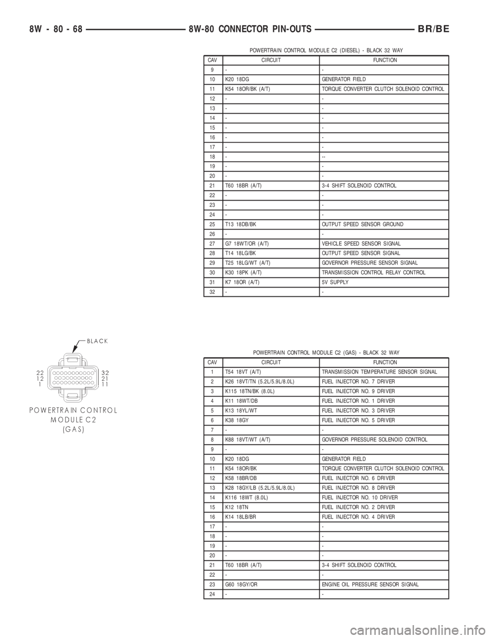
POWERTRAIN CONTROL MODULE C2 (DIESEL) - BLACK 32 WAY
CAV CIRCUIT FUNCTION
9- -
10 K20 18DG GENERATOR FIELD
11 K54 18OR/BK (A/T) TORQUE CONVERTER CLUTCH SOLENOID CONTROL
12 - -
13 - -
14 - -
15 - -
16 - -
17 - -
18 - --
19 - -
20 - -
21 T60 18BR (A/T) 3-4 SHIFT SOLENOID CONTROL
22 - -
23 - -
24 - -
25 T13 18DB/BK OUTPUT SPEED SENSOR GROUND
26 - -
27 G7 18WT/OR (A/T) VEHICLE SPEED SENSOR SIGNAL
28 T14 18LG/BK OUTPUT SPEED SENSOR SIGNAL
29 T25 18LG/WT (A/T) GOVERNOR PRESSURE SENSOR SIGNAL
30 K30 18PK (A/T) TRANSMISSION CONTROL RELAY CONTROL
31 K7 18OR (A/T) 5V SUPPLY
32 - -
POWERTRAIN CONTROL MODULE C2 (GAS) - BLACK 32 WAY
CAV CIRCUIT FUNCTION
1 T54 18VT (A/T) TRANSMISSION TEMPERATURE SENSOR SIGNAL
2 K26 18VT/TN (5.2L/5.9L/8.0L) FUEL INJECTOR NO. 7 DRIVER
3 K115 18TN/BK (8.0L) FUEL INJECTOR NO. 9 DRIVER
4 K11 18WT/DB FUEL INJECTOR NO. 1 DRIVER
5 K13 18YL/WT FUEL INJECTOR NO. 3 DRIVER
6 K38 18GY FUEL INJECTOR NO. 5 DRIVER
7- -
8 K88 18VT/WT (A/T) GOVERNOR PRESSURE SOLENOID CONTROL
9- -
10 K20 18DG GENERATOR FIELD
11 K54 18OR/BK TORQUE CONVERTER CLUTCH SOLENOID CONTROL
12 K58 18BR/DB FUEL INJECTOR NO. 6 DRIVER
13 K28 18GY/LB (5.2L/5.9L/8.0L) FUEL INJECTOR NO. 8 DRIVER
14 K116 18WT (8.0L) FUEL INJECTOR NO. 10 DRIVER
15 K12 18TN FUEL INJECTOR NO. 2 DRIVER
16 K14 18LB/BR FUEL INJECTOR NO. 4 DRIVER
17 - -
18 - -
19 - -
20 - -
21 T60 18BR (A/T) 3-4 SHIFT SOLENOID CONTROL
22 - -
23 G60 18GY/OR ENGINE OIL PRESSURE SENSOR SIGNAL
24 - -
8W - 80 - 68 8W-80 CONNECTOR PIN-OUTSBR/BE
Page 1124 of 2889
8W-95 SPLICE LOCATIONS
TABLE OF CONTENTS
page
SPLICE LOCATIONS
DESCRIPTION............................1
SPLICE LOCATIONS
DESCRIPTION
This section provides illustrations identifying the
general location of the splices in this vehicle. A spliceindex is provided. Use the wiring diagrams in each
section for splice number identification. Refer to the
index for proper splice number. For splices that are
not shown in the figures N/S appears in the Fig. col-
umn.
Splice Number Location Fig.
S100 Engine Harness Near T/O to Oil Pressure Sensor 3
S102 Headlamp and Dash Harness, Near T/O to Right Park/Turn Lamp 8
S103 Headlamp and Dash Harness, Near T/O to Left Park/Turn Lamp N/S
S104 Headlamp and Dash Harness, Near T/O to Left Front Headlamp N/S
S105 Headlamp and Dash Harness, In Power Distribution Center 7
S106 Headlamp and Dash Harness, In Power Distribution Center 7
S107 Headlamp and Dash Harness, Near Left Wheel Speed Sensor 7
S108 Headlamp and Dash Harness, Near Daytime Running Lamp Module 7
S109 Battery Harness, In T/O for Engine and Transmission Ground N/S
S110 Headlamp and Dash Harness, Near Left Wheel Speed Sensor 7
S111 Transmission Harness Near T/O to A/C Low Pressure Switch 2
S112 Headlamp and Dash Harness, Near Antilock Brake Controller 7
S113 Headlamp and Dash Harness, Near Antilock Brake Controller 7
S114 Headlamp and Dash Harness, In T/O to Chassis Harness 7
S116(V6, V8) Engine Harness, Near T/O to Fuel Injectors 1
S116 (V10) Engine Harness Rear of Engine 2, 4
S116 (Diesel) Transmission Harness, In T/O to Power Distribution Center 2
S117 (V6, V8) Engine Harness, Near T/O to Fuel Injectors 1
S117 (V10) Engine Harness, Near T/O to fuel Injector No. 8 1, 4
S118 (V6, V8) Engine Harness, Near T/O to Fuel Injectors 1
S118 (V10) Engine Harness, Rear of Engine 1, 4
S119 (V6, V8) Engine Harness, Near T/O to Fuel Injectors 1
S119 (V10) Engine Harness, Rear of Engine 1, 4
S120 (V6, V8) Engine Harness, Near T/O to Fuel Injectors 1
S120 (V10) Engine Harness, Rear of Engine 2, 4, 6
S120 (Diesel) Transmission Harness, Near T/O to A/C Low Pressure Switch 2
S121 (V6, V8) Engine Harness, Near T/O to Fuel Injector No. 5 3
S121 (V10) Engine Harness, Near T/O to Fuel Injector No. 7 4
S122 (V6, V8) Engine Harness, Top of Transmission 5
S122 (V10) Engine Harness, In T/O to Transmission N/S
S123 (V6, V8) Engine Harness, Near T/O to Fuel Injector No. 3 3
BR/BE8W-95 SPLICE LOCATIONS 8W - 95 - 1
Page 1125 of 2889
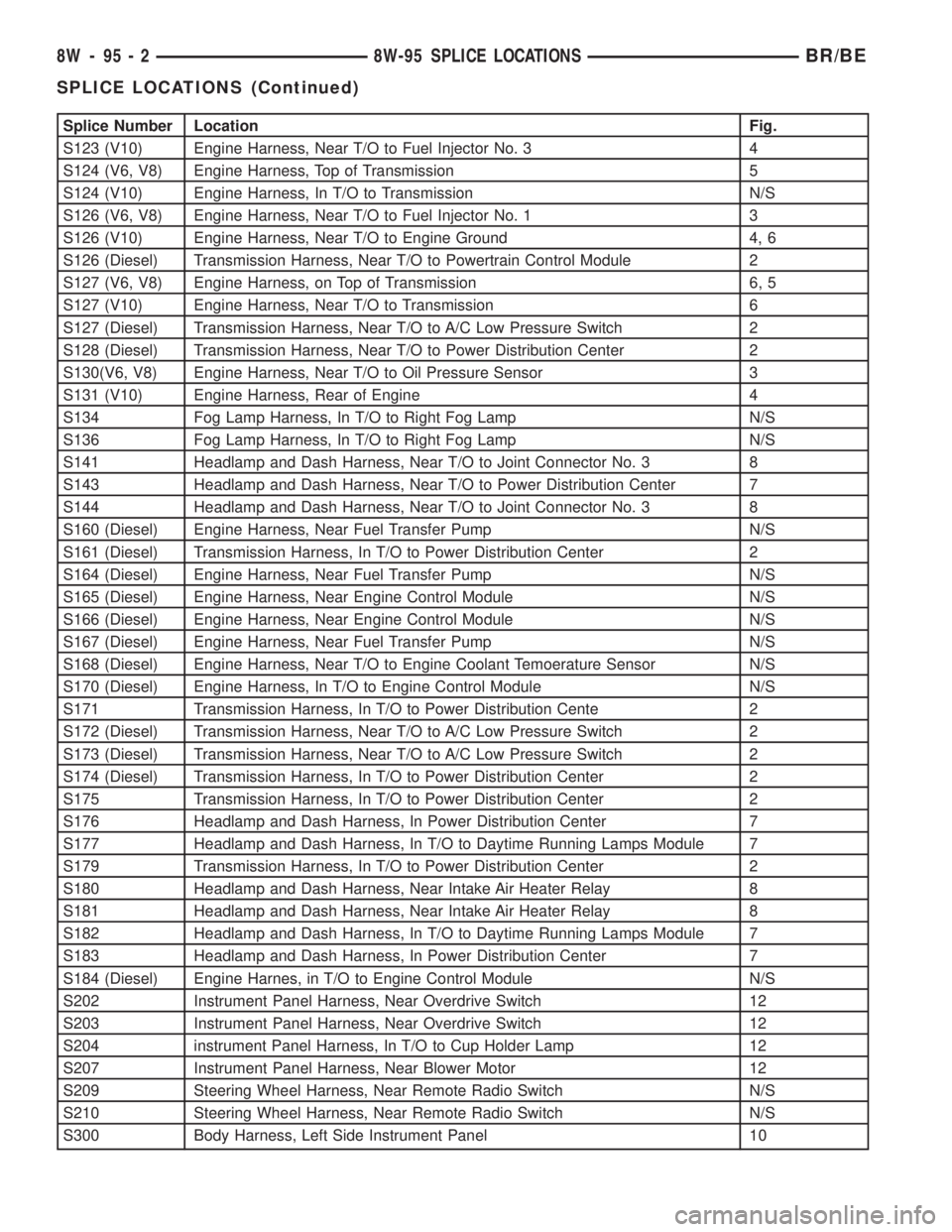
Splice Number Location Fig.
S123 (V10) Engine Harness, Near T/O to Fuel Injector No. 3 4
S124 (V6, V8) Engine Harness, Top of Transmission 5
S124 (V10) Engine Harness, In T/O to Transmission N/S
S126 (V6, V8) Engine Harness, Near T/O to Fuel Injector No. 1 3
S126 (V10) Engine Harness, Near T/O to Engine Ground 4, 6
S126 (Diesel) Transmission Harness, Near T/O to Powertrain Control Module 2
S127 (V6, V8) Engine Harness, on Top of Transmission 6, 5
S127 (V10) Engine Harness, Near T/O to Transmission 6
S127 (Diesel) Transmission Harness, Near T/O to A/C Low Pressure Switch 2
S128 (Diesel) Transmission Harness, Near T/O to Power Distribution Center 2
S130(V6, V8) Engine Harness, Near T/O to Oil Pressure Sensor 3
S131 (V10) Engine Harness, Rear of Engine 4
S134 Fog Lamp Harness, In T/O to Right Fog Lamp N/S
S136 Fog Lamp Harness, In T/O to Right Fog Lamp N/S
S141 Headlamp and Dash Harness, Near T/O to Joint Connector No. 3 8
S143 Headlamp and Dash Harness, Near T/O to Power Distribution Center 7
S144 Headlamp and Dash Harness, Near T/O to Joint Connector No. 3 8
S160 (Diesel) Engine Harness, Near Fuel Transfer Pump N/S
S161 (Diesel) Transmission Harness, In T/O to Power Distribution Center 2
S164 (Diesel) Engine Harness, Near Fuel Transfer Pump N/S
S165 (Diesel) Engine Harness, Near Engine Control Module N/S
S166 (Diesel) Engine Harness, Near Engine Control Module N/S
S167 (Diesel) Engine Harness, Near Fuel Transfer Pump N/S
S168 (Diesel) Engine Harness, Near T/O to Engine Coolant Temoerature Sensor N/S
S170 (Diesel) Engine Harness, In T/O to Engine Control Module N/S
S171 Transmission Harness, In T/O to Power Distribution Cente 2
S172 (Diesel) Transmission Harness, Near T/O to A/C Low Pressure Switch 2
S173 (Diesel) Transmission Harness, Near T/O to A/C Low Pressure Switch 2
S174 (Diesel) Transmission Harness, In T/O to Power Distribution Center 2
S175 Transmission Harness, In T/O to Power Distribution Center 2
S176 Headlamp and Dash Harness, In Power Distribution Center 7
S177 Headlamp and Dash Harness, In T/O to Daytime Running Lamps Module 7
S179 Transmission Harness, In T/O to Power Distribution Center 2
S180 Headlamp and Dash Harness, Near Intake Air Heater Relay 8
S181 Headlamp and Dash Harness, Near Intake Air Heater Relay 8
S182 Headlamp and Dash Harness, In T/O to Daytime Running Lamps Module 7
S183 Headlamp and Dash Harness, In Power Distribution Center 7
S184 (Diesel) Engine Harnes, in T/O to Engine Control Module N/S
S202 Instrument Panel Harness, Near Overdrive Switch 12
S203 Instrument Panel Harness, Near Overdrive Switch 12
S204 instrument Panel Harness, In T/O to Cup Holder Lamp 12
S207 Instrument Panel Harness, Near Blower Motor 12
S209 Steering Wheel Harness, Near Remote Radio Switch N/S
S210 Steering Wheel Harness, Near Remote Radio Switch N/S
S300 Body Harness, Left Side Instrument Panel 10
8W - 95 - 2 8W-95 SPLICE LOCATIONSBR/BE
SPLICE LOCATIONS (Continued)