2001 DODGE RAM transmission oil
[x] Cancel search: transmission oilPage 276 of 2889
WARNING
WARNING: DUST AND DIRT ACCUMULATING ON
BRAKE PARTS DURING NORMAL USE MAY CON-
TAIN ASBESTOS FIBERS FROM PRODUCTION OR
AFTERMARKET LININGS. BREATHING EXCESSIVE
CONCENTRATIONS OF ASBESTOS FIBERS CAN
CAUSE SERIOUS BODILY HARM. EXERCISE CARE
WHEN SERVICING BRAKE PARTS. DO NOT CLEAN
BRAKE PARTS WITH COMPRESSED AIR OR BY
DRY BRUSHING. USE A VACUUM CLEANER SPE-
CIFICALLY DESIGNED FOR THE REMOVAL OF
ASBESTOS FIBERS FROM BRAKE COMPONENTS.
IF A SUITABLE VACUUM CLEANER IS NOT AVAIL-
ABLE, CLEANING SHOULD BE DONE WITH A
WATER DAMPENED CLOTH. DO NOT SAND, OR
GRIND BRAKE LINING UNLESS EQUIPMENT USED
IS DESIGNED TO CONTAIN THE DUST RESIDUE.
DISPOSE OF ALL RESIDUE CONTAINING ASBES-
TOS FIBERS IN SEALED BAGS OR CONTAINERS
TO MINIMIZE EXPOSURE TO YOURSELF AND OTH-
ERS. FOLLOW PRACTICES PRESCRIBED BY THE
OCCUPATIONAL SAFETY AND HEALTH ADMINIS-
TRATION AND THE ENVIRONMENTAL PROTECTION
AGENCY FOR THE HANDLING, PROCESSING, AND
DISPOSITION OF DUST OR DEBRIS THAT MAY
CONTAIN ASBESTOS FIBERS.
CAUTION: Never use gasoline, kerosene, alcohol,
motor oil, transmission fluid, or any fluid containing
mineral oil to clean the system components. These
fluids damage rubber cups and seals. Use only
fresh brake fluid or Mopar brake cleaner to clean or
flush brake system components. These are the only
cleaning materials recommended. If system contam-
ination is suspected, check the fluid for dirt, discol-
oration, or separation into distinct layers. Also
check the reservoir cap seal for distortion. Drain
and flush the system with new brake fluid if con-
tamination is suspected.
CAUTION: Use Mopar brake fluid, or an equivalent
quality fluid meeting SAE/DOT standards J1703 and
DOT 3. Brake fluid must be clean and free of con-
taminants. Use fresh fluid from sealed containers
only to ensure proper antilock component opera-
tion.
CAUTION: Use Mopar multi-mileage or high temper-
ature grease to lubricate caliper slide surfaces,
drum brake pivot pins, and shoe contact points on
the backing plates. Use multi-mileage grease or GE
661 or Dow 111 silicone grease on caliper slide pins
to ensure proper operation.
DIAGNOSIS AND TESTING - BASE BRAKE
SYSTEM
Base brake components consist of the brake shoes,
calipers, wheel cylinders, brake drums, rotors, brake
lines, master cylinder, booster, and parking brake
components.
Brake diagnosis involves determining if the prob-
lem is related to a mechanical, hydraulic, or vacuum
operated component.
The first diagnosis step is the preliminary check.
PRELIMINARY BRAKE CHECK
(1) Check condition of tires and wheels. Damaged
wheels and worn, damaged, or underinflated tires
can cause pull, shudder, vibration, and a condition
similar to grab.
(2) If complaint was based on noise when braking,
check suspension components. Jounce front and rear
of vehicle and listen for noise that might be caused
by loose, worn or damaged suspension or steering
components.
(3) Inspect brake fluid level and condition. Note
that the brake reservoir fluid level will decrease in
proportion to normal lining wear.Also note that
brake fluid tends to darken over time. This is
normal and should not be mistaken for contam-
ination.
(a) If fluid level is abnormally low, look for evi-
dence of leaks at calipers, wheel cylinders, brake
lines, and master cylinder.
(b) If fluid appears contaminated, drain out a
sample to examine. System will have to be flushed
if fluid is separated into layers, or contains a sub-
stance other than brake fluid. The system seals
and cups will also have to be replaced after flush-
ing. Use clean brake fluid to flush the system.
(4) Check parking brake operation. Verify free
movement and full release of cables and pedal. Also
note if vehicle was being operated with parking
brake partially applied.
(5) Check brake pedal operation. Verify that pedal
does not bind and has adequate free play. If pedal
lacks free play, check pedal and power booster for
being loose or for bind condition. Do not road test
until condition is corrected.
(6) Check booster vacuum check valve and hose.
(7) If components checked appear OK, road test
the vehicle.
ROAD TESTING
(1) If complaint involved low brake pedal, pump
pedal and note if it comes back up to normal height.
(2) Check brake pedal response with transmission
in Neutral and engine running. Pedal should remain
firm under constant foot pressure.
BR/BEBRAKES 5 - 5
HYDRAULIC/MECHANICAL (Continued)
Page 286 of 2889
SPECIFICATIONS
BRAKE FLUID
The brake fluid used in this vehicle must conform
to DOT 3 specifications and SAE J1703 standards.
No other type of brake fluid is recommended or
approved for usage in the vehicle brake system. Use
only Mopar brake fluid or an equivalent from a
tightly sealed container.
CAUTION: Never use reclaimed brake fluid or fluid
from an container which has been left open. An
open container of brake fluid will absorb moisture
from the air and contaminate the fluid.
CAUTION: Never use any type of a petroleum-based
fluid in the brake hydraulic system. Use of such
type fluids will result in seal damage of the vehicle
brake hydraulic system causing a failure of the
vehicle brake system. Petroleum based fluids would
be items such as engine oil, transmission fluid,
power steering fluid, etc.
FLUID RESERVOIR
REMOVAL
(1) Remove reservoir cap and empty fluid into
drain container.
(2) Clamp cylinder body in vise with brass protec-
tive jaws.
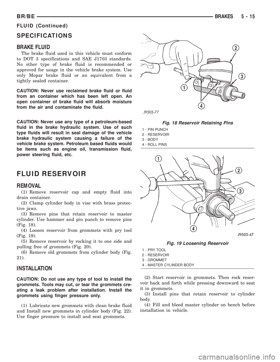
(3) Remove pins that retain reservoir to master
cylinder. Use hammer and pin punch to remove pins
(Fig. 18).
(4) Loosen reservoir from grommets with pry tool
(Fig. 19).
(5) Remove reservoir by rocking it to one side and
pulling free of grommets (Fig. 20).
(6) Remove old grommets from cylinder body (Fig.
21).
INSTALLATION
CAUTION: Do not use any type of tool to install the
grommets. Tools may cut, or tear the grommets cre-
ating a leak problem after installation. Install the
grommets using finger pressure only.
(1) Lubricate new grommets with clean brake fluid
and Install new grommets in cylinder body (Fig. 22).
Use finger pressure to install and seat grommets.(2) Start reservoir in grommets. Then rock reser-
voir back and forth while pressing downward to seat
it in grommets.
(3) Install pins that retain reservoir to cylinder
body.
(4) Fill and bleed master cylinder on bench before
installation in vehicle.
Fig. 18 Reservoir Retaining Pins
1 - PIN PUNCH
2 - RESERVOIR
3 - BODY
4 - ROLL PINS
Fig. 19 Loosening Reservoir
1-PRYTOOL
2 - RESERVOIR
3 - GROMMET
4 - MASTER CYLINDER BODY
BR/BEBRAKES 5 - 15
FLUID (Continued)
Page 315 of 2889
WARNING
WARNING:: EXERCISE CARE WHEN SERVICING
CLUTCH COMPONENTS. FACTORY INSTALLED
CLUTCH DISCS DO NOT CONTAIN ASBESTOS
FIBERS. DUST AND DIRT ON CLUTCH PARTS MAY
CONTAIN ASBESTOS FIBERS FROM AFTERMAR-
KET COMPONENTS. BREATHING EXCESSIVE CON-
CENTRATIONS OF THESE FIBERS CAN CAUSE
SERIOUS BODILY HARM. WEAR A RESPIRATOR
DURING SERVICE AND NEVER CLEAN CLUTCH
COMPONENTS WITH COMPRESSED AIR OR WITH
A DRY BRUSH. EITHER CLEAN THE COMPONENTS
WITH A WATER DAMPENED RAGS OR USE A VAC-
UUM CLEANER SPECIFICALLY DESIGNED FOR
REMOVING ASBESTOS FIBERS AND DUST. DO NOT
CREATE DUST BY SANDING A CLUTCH DISC.
REPLACE THE DISC IF THE FRICTION MATERIAL IS
DAMAGED OR CONTAMINATED. DISPOSE OF ALL
DUST AND DIRT CONTAINING ASBESTOS FIBERS
IN SEALED BAGS OR CONTAINERS. THIS WILL
HELP MINIMIZE EXPOSURE TO YOURSELF AND TO
OTHERS. FOLLOW ALL RECOMMENDED SAFETY
PRACTICES PRESCRIBED BY THE OCCUPATIONAL
SAFETY AND HEALTH ADMINISTRATION (OSHA)
AND THE ENVIRONMENTAL SAFETY AGENCY
(EPA), FOR THE HANDLING AND DISPOSAL OF
PRODUCTS CONTAINING ASBESTOS.
DIAGNOSTIC AND TESTING - CLUTCH
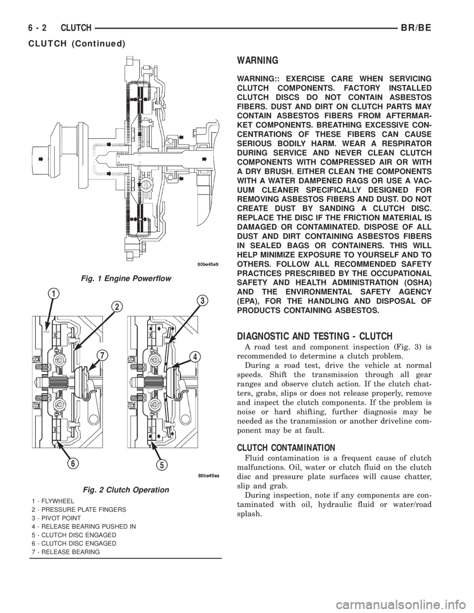
A road test and component inspection (Fig. 3) is
recommended to determine a clutch problem.
During a road test, drive the vehicle at normal
speeds. Shift the transmission through all gear
ranges and observe clutch action. If the clutch chat-
ters, grabs, slips or does not release properly, remove
and inspect the clutch components. If the problem is
noise or hard shifting, further diagnosis may be
needed as the transmission or another driveline com-
ponent may be at fault.
CLUTCH CONTAMINATION
Fluid contamination is a frequent cause of clutch
malfunctions. Oil, water or clutch fluid on the clutch
disc and pressure plate surfaces will cause chatter,
slip and grab.
During inspection, note if any components are con-
taminated with oil, hydraulic fluid or water/road
splash.
Fig. 1 Engine Powerflow
Fig. 2 Clutch Operation
1 - FLYWHEEL
2 - PRESSURE PLATE FINGERS
3 - PIVOT POINT
4 - RELEASE BEARING PUSHED IN
5 - CLUTCH DISC ENGAGED
6 - CLUTCH DISC ENGAGED
7 - RELEASE BEARING
6 - 2 CLUTCHBR/BE
CLUTCH (Continued)
Page 317 of 2889
Oil contamination indicates a leak at either the
rear main seal or transmission input shaft. Oil leak-
age produces a residue of oil on the housing interior
and on the clutch cover and flywheel. Heat buildup
caused by slippage between the cover, disc and fly-
wheel, can sometimes bake the oil residue onto the
components. The glaze-like residue ranges in color
from amber to black.
Road splash contamination means dirt/water is
entering the clutch housing due to loose bolts, hous-
ing cracks or through hydraulic line openings. Driv-
ing through deep water puddles can force water/road
splash into the housing through such openings.
Clutch fluid leaks are usually from damaged slave
cylinder push rod seals.
IMPROPER RELEASE OR CLUTCH ENGAGEMENT
Clutch release or engagement problems are caused
by wear or damage to one or more clutch compo-
nents. A visual inspection of the release components
will usually reveal the problem part.
Release problems can result in hard shifting and
noise. Items to look for are: leaks at the clutch cylin-
ders and interconnecting line; loose slave cylinder
bolts; worn/loose release fork and pivot stud; dam-
aged release bearing; and a worn clutch disc, or pres-
sure plate.
Normal condensation in vehicles that are stored or
out of service for long periods of time can generate
enough corrosion to make the disc stick to the fly-
wheel, or pressure plate. If this condition is experi-
enced, correction only requires that the disc be
loosened manually through the inspection plate open-
ing.
Engagement problems usually result in slip, chat-
ter/shudder, and noisy operation. The primary causes
are clutch disc contamination; clutch disc wear; mis-
alignment, or distortion; flywheel damage; or a com-
bination of the foregoing. A visual inspection is
required to determine the part actually causing the
problem.
CLUTCH MISALIGNMENT
Clutch components must be in proper alignment
with the crankshaft and transmission input shaft.
Misalignment caused by excessive runout or warpage
of any clutch component will cause grab, chatter and
improper clutch release.
CLUTCH COVER AND DISC RUNOUT
Check the clutch disc before installation. Axial
(face) runout of anewdisc should not exceed 0.50
mm (0.020 in.). Measure runout about 6 mm (1/4 in.)
from the outer edge of the disc facing. Obtain
another disc if runout is excessive.Check condition of the clutch before installation. A
warped cover or diaphragm spring will cause grab
and incomplete release or engagement. Be careful
when handling the cover and disc. Impact can distort
the cover, diaphragm spring, release fingers and the
hub of the clutch disc.
Use an alignment tool when positioning the disc on
the flywheel. The tool prevents accidental misalign-
ment which could result in cover distortion and disc
damage.
A frequent cause of clutch cover distortion (and con-
sequent misalignment) is improper bolt tightening.
CLUTCH FLYWHEEL RUNOUT
Check flywheel runout whenever misalignment is
suspected. Flywheel runout should not exceed 0.08
mm (0.003 in.). Measure runout at the outer edge of
the flywheel face with a dial indicator. Mount the
indicator on the rear face of the engine block.
Common causes of runout are:
²heat warpage
²improper machining
²incorrect bolt tightening
²improper seating on crankshaft flange shoulder
²foreign material on crankshaft flange
Flywheel machining is not recommended. The fly-
wheel clutch surface is machined to a unique contour
and machining will negate this feature. However,
minor flywheel scoring can be cleaned up by hand with
180 grit emery, or with surface grinding equipment.
Remove only enough material to reduce scoring
(approximately 0.001 - 0.003 in.). Heavy stock removal
isnot recommended.
Replace the flywheel if scoring
is severe and deeper than 0.076 mm (0.003 in.).
Excessive stock removal can result in flywheel crack-
ing or warpage after installation; it can also weaken
the flywheel and interfere with proper clutch release.
Clean the crankshaft flange before mounting the
flywheel. Dirt and grease on the flange surface may
cock the flywheel causing excessive runout. Use new
bolts when remounting a flywheel and secure the
bolts with MopartLock And Seal. Tighten flywheel
bolts to specified torque only. Overtightening can dis-
tort the flywheel hub causing runout.
DIAGNOSIS CHART
The clutch inspection chart (Fig. 3) outlines items to
be checked before and during clutch installation. Use
the chart as a check list to help avoid overlooking
potential problem sources during service operations.
The diagnosis charts describe common clutch prob-
lems, causes and correction. Fault conditions are listed
at the top of each chart. Conditions, causes and correc-
tive action are outlined in the indicated columns.
The charts are provided as a convenient reference
when diagnosing faulty clutch operation.
6 - 4 CLUTCHBR/BE
CLUTCH (Continued)
Page 318 of 2889
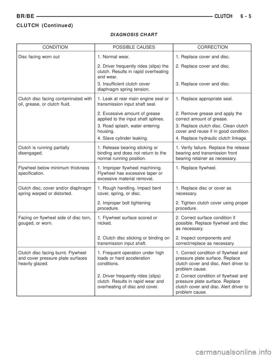
DIAGNOSIS CHART
CONDITION POSSIBLE CAUSES CORRECTION
Disc facing worn out 1. Normal wear. 1. Replace cover and disc.
2. Driver frequently rides (slips) the
clutch. Results in rapid overheating
and wear.2. Replace cover and disc.
3. Insufficient clutch cover
diaphragm spring tension.3. Replace cover and disc.
Clutch disc facing contaminated with
oil, grease, or clutch fluid.1. Leak at rear main engine seal or
transmission input shaft seal.1. Replace appropriate seal.
2. Excessive amount of grease
applied to the input shaft splines.2. Remove grease and apply the
correct amount of grease.
3. Road splash, water entering
housing.3. Replace clutch disc. Clean clutch
cover and reuse if in good condition.
4. Slave cylinder leaking. 4. Replace hydraulic clutch linkage.
Clutch is running partially
disengaged.1. Release bearing sticking or
binding and does not return to the
normal running position.1. Verify failure. Replace the release
bearing and transmission front
bearing retainer as necessary.
Flywheel below minimum thickness
specification.1. Improper flywheel machining.
Flywheel has excessive taper or
excessive material removal.1. Replace flywheel.
Clutch disc, cover and/or diaphragm
spring warped or distorted.1. Rough handling. Impact bent
cover, spring, or disc.1. Replace disc or cover as
necessary.
2. Improper bolt tightening
procedure.2. Tighten clutch cover using proper
procedure.
Facing on flywheel side of disc torn,
gouged, or worn.1. Flywheel surface scored or
nicked.2. Correct surface condition if
possible. Replace flywheel and disc
as necessary.
2. Clutch disc sticking or binding on
transmission input shaft.2. Inspect components and
correct/replace as necessary.
Clutch disc facing burnt. Flywheel
and cover pressure plate surfaces
heavily glazed.1. Frequent operation under high
loads or hard acceleration
conditions.1. Correct condition of flywheel and
pressure plate surface. Replace
clutch cover and disc. Alert driver to
problem cause.
2. Driver frequently rides (slips)
clutch. Results in rapid wear and
overheating of disc and cover.2. Correct condition of flywheel and
pressure plate surface. Replace
clutch cover and disc. Alert driver to
problem cause.
BR/BECLUTCH 6 - 5
CLUTCH (Continued)
Page 336 of 2889
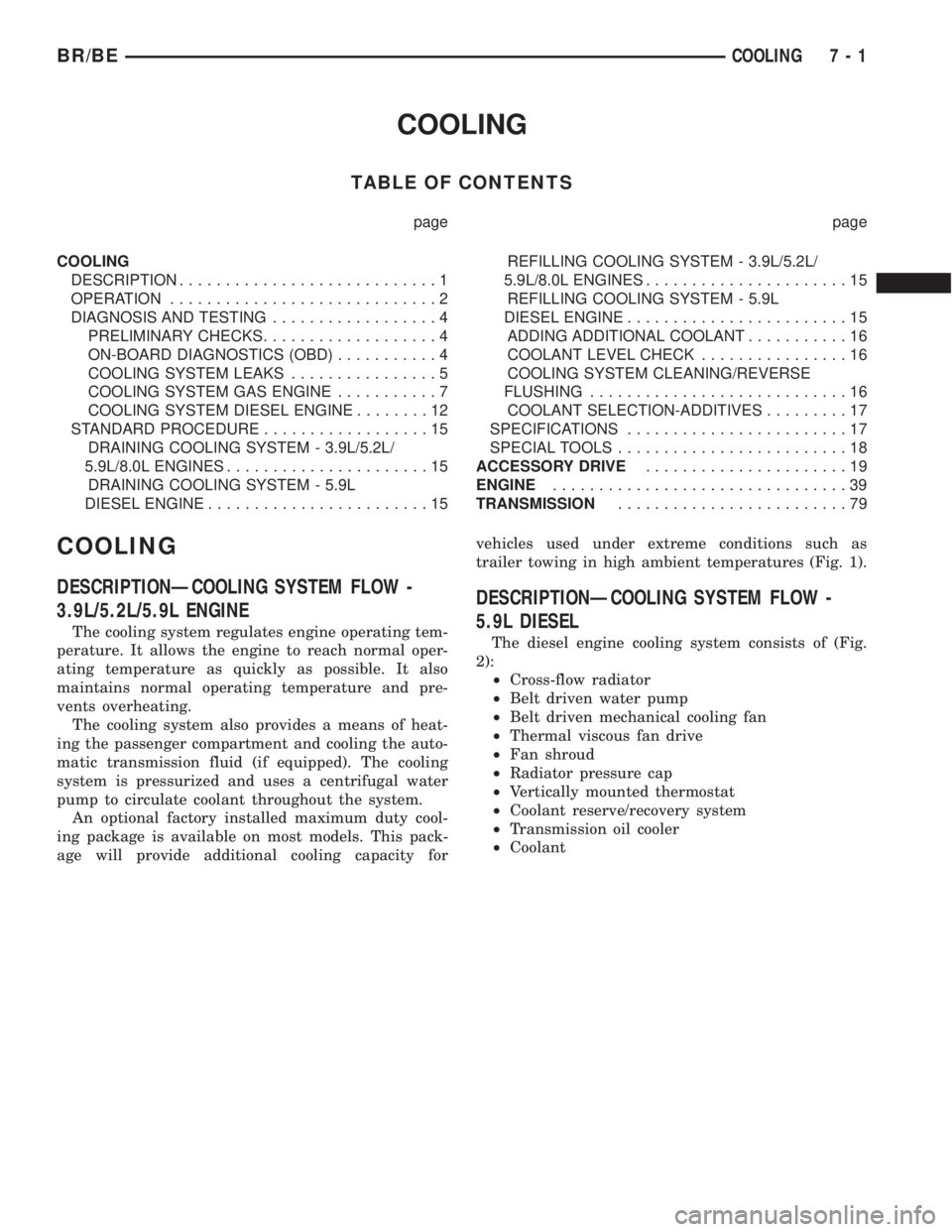
COOLING
TABLE OF CONTENTS
page page
COOLING
DESCRIPTION............................1
OPERATION.............................2
DIAGNOSIS AND TESTING..................4
PRELIMINARY CHECKS...................4
ON-BOARD DIAGNOSTICS (OBD)...........4
COOLING SYSTEM LEAKS................5
COOLING SYSTEM GAS ENGINE...........7
COOLING SYSTEM DIESEL ENGINE........12
STANDARD PROCEDURE..................15
DRAINING COOLING SYSTEM - 3.9L/5.2L/
5.9L/8.0L ENGINES......................15
DRAINING COOLING SYSTEM - 5.9L
DIESEL ENGINE........................15REFILLING COOLING SYSTEM - 3.9L/5.2L/
5.9L/8.0L ENGINES......................15
REFILLING COOLING SYSTEM - 5.9L
DIESEL ENGINE........................15
ADDING ADDITIONAL COOLANT...........16
COOLANT LEVEL CHECK................16
COOLING SYSTEM CLEANING/REVERSE
FLUSHING............................16
COOLANT SELECTION-ADDITIVES.........17
SPECIFICATIONS........................17
SPECIAL TOOLS.........................18
ACCESSORY DRIVE......................19
ENGINE................................39
TRANSMISSION.........................79
COOLING
DESCRIPTIONÐCOOLING SYSTEM FLOW -
3.9L/5.2L/5.9L ENGINE
The cooling system regulates engine operating tem-
perature. It allows the engine to reach normal oper-
ating temperature as quickly as possible. It also
maintains normal operating temperature and pre-
vents overheating.
The cooling system also provides a means of heat-
ing the passenger compartment and cooling the auto-
matic transmission fluid (if equipped). The cooling
system is pressurized and uses a centrifugal water
pump to circulate coolant throughout the system.
An optional factory installed maximum duty cool-
ing package is available on most models. This pack-
age will provide additional cooling capacity forvehicles used under extreme conditions such as
trailer towing in high ambient temperatures (Fig. 1).
DESCRIPTIONÐCOOLING SYSTEM FLOW -
5.9L DIESEL
The diesel engine cooling system consists of (Fig.
2):
²Cross-flow radiator
²Belt driven water pump
²Belt driven mechanical cooling fan
²Thermal viscous fan drive
²Fan shroud
²Radiator pressure cap
²Vertically mounted thermostat
²Coolant reserve/recovery system
²Transmission oil cooler
²Coolant
BR/BECOOLING 7 - 1
Page 337 of 2889
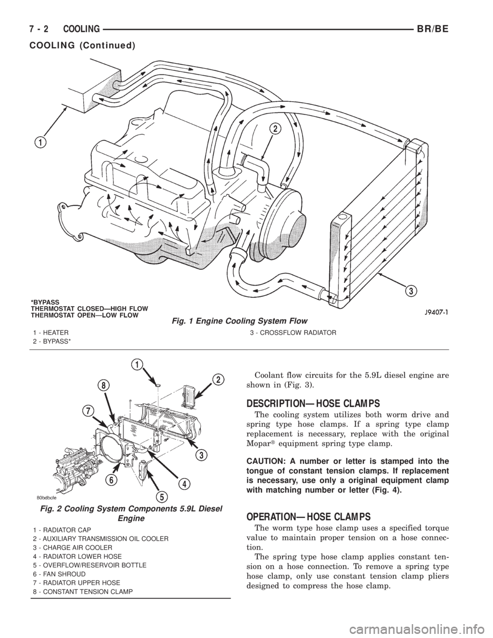
Coolant flow circuits for the 5.9L diesel engine are
shown in (Fig. 3).
DESCRIPTIONÐHOSE CLAMPS
The cooling system utilizes both worm drive and
spring type hose clamps. If a spring type clamp
replacement is necessary, replace with the original
Mopartequipment spring type clamp.
CAUTION: A number or letter is stamped into the
tongue of constant tension clamps. If replacement
is necessary, use only a original equipment clamp
with matching number or letter (Fig. 4).
OPERATIONÐHOSE CLAMPS
The worm type hose clamp uses a specified torque
value to maintain proper tension on a hose connec-
tion.
The spring type hose clamp applies constant ten-
sion on a hose connection. To remove a spring type
hose clamp, only use constant tension clamp pliers
designed to compress the hose clamp.
Fig. 1 Engine Cooling System Flow
1 - HEATER
2 - BYPASS*3 - CROSSFLOW RADIATOR
Fig. 2 Cooling System Components 5.9L Diesel
Engine
1 - RADIATOR CAP
2 - AUXILIARY TRANSMISSION OIL COOLER
3 - CHARGE AIR COOLER
4 - RADIATOR LOWER HOSE
5 - OVERFLOW/RESERVOIR BOTTLE
6 - FAN SHROUD
7 - RADIATOR UPPER HOSE
8 - CONSTANT TENSION CLAMP
7 - 2 COOLINGBR/BE
COOLING (Continued)
Page 341 of 2889
hoses, gasket edges and heater. Seal small leak holes
with a Sealer Lubricant (or equivalent). Repair leak
holes and inspect system again with pressure
applied.
Drops Quickly:Indicates that serious leakage is
occurring. Examine system for external leakage. If
leaks are not visible, inspect for internal leakage.
Large radiator leak holes should be repaired by a
reputable radiator repair shop.
INTERNAL LEAKAGE INSPECTION
Remove engine oil pan drain plug and drain a
small amount of engine oil. If coolant is present in
the pan, it will drain first because it is heavier than
oil. An alternative method is to operate engine for a
short period to churn the oil. After this is done,
remove engine dipstick and inspect for water glob-
ules. Also inspect transmission dipstick for water
globules and transmission fluid cooler for leakage.
WARNING: WITH RADIATOR PRESSURE TESTER
TOOL INSTALLED ON RADIATOR, DO NOT ALLOW
PRESSURE TO EXCEED 110 KPA (20 PSI). PRES-
SURE WILL BUILD UP QUICKLY IF A COMBUSTION
LEAK IS PRESENT. TO RELEASE PRESSURE,
ROCK TESTER FROM SIDE TO SIDE. WHEN
REMOVING TESTER, DO NOT TURN TESTER MORE
THAN 1/2 TURN IF SYSTEM IS UNDER PRESSURE.
Operate engine without pressure cap on radiator
until thermostat opens. Attach a Pressure Tester to
filler neck. If pressure builds up quickly it indicates a
combustion leak exists. This is usually the result of a
cylinder head gasket leak or crack in engine. Repair
as necessary.
If there is not an immediate pressure increase,
pump the Pressure Tester. Do this until indicated
pressure is within system range of 110 kPa (16 psi).
Fluctuation of gauge pointer indicates compression or
combustion leakage into cooling system.
Because the vehicle is equipped with a catalytic
converter,do notremove spark plug cables or short
out cylinders to isolate compression leak.If the needle on dial of pressure tester does not
fluctuate, race engine a few times to check for an
abnormal amount of coolant or steam. This would be
emitting from exhaust pipe. Coolant or steam from
exhaust pipe may indicate a faulty cylinder head gas-
ket, cracked engine cylinder block or cylinder head.
A convenient check for exhaust gas leakage into
cooling system is provided by a commercially avail-
able Block Leak Check tool. Follow manufacturers
instructions when using this product.COMBUSTION LEAKAGE TESTÐWITHOUT
PRESSURE TESTER
DO NOT WASTE reusable coolant. If solution is
clean, drain coolant into a clean container for reuse.
WARNING: DO NOT REMOVE CYLINDER BLOCK
DRAIN PLUGS OR LOOSEN RADIATOR DRAIN-
COCK WITH SYSTEM HOT AND UNDER PRESSURE.
SERIOUS BURNS FROM COOLANT CAN OCCUR.
Drain sufficient coolant to allow thermostat
removal. (Refer to 7 - COOLING/ENGINE/ENGINE
COOLANT THERMOSTAT - REMOVAL). Remove
accessory drive belt (Refer to 7 - COOLING/ACCES-
SORY DRIVE/DRIVE BELTS - REMOVAL).
Add coolant to radiator to bring level to within 6.3
mm (1/4 in) of top of thermostat housing.
CAUTION: Avoid overheating. Do not operate
engine for an excessive period of time. Open drain-
cock immediately after test to eliminate boil over.
Start engine and accelerate rapidly three times, to
approximately 3000 rpm while observing coolant. If
internal engine combustion gases are leaking into
cooling system, bubbles will appear in coolant. If bub-
bles do not appear, internal combustion gas leakage
is not present.
7 - 6 COOLINGBR/BE
COOLING (Continued)