2001 DODGE RAM airbag off
[x] Cancel search: airbag offPage 2678 of 2889
hook formations on the lower edge of the glove box
door are engaged with and pivot on three hinge pins
integral to the lower edge of the instrument panel
support structure. The glove box door also serves as
the passenger side knee blocker. A honeycomb struc-
ture between the inner and outer glove box door pan-
els helps to absorb the impact load and distribute it
to the instrument panel structure.
²Steering Column Opening Cover- The steer-
ing column opening cover serves as the driver side
knee blocker. This molded plastic cover has an inte-
gral ribbed plastic liner concealed behind it, for
increased strength and integrity. The steering column
opening cover transfers impact loads to the instru-
ment panel structural support.
²Top Cover- The instrument panel top cover or
base trim is the molded, grained, and color impreg-
nated plastic outer skin of the instrument panel
structural support.
Hard wired circuitry connects the electrical compo-
nents on the instrument panel to each other through
the electrical system of the vehicle. These hard wired
circuits are integral to several wire harnesses, which
are routed throughout the vehicle and retained by
many different methods. These circuits may be con-
nected to each other, to the vehicle electrical system
and to the instrument panel components through the
use of a combination of soldered splices, splice block
connectors and many different types of wire harness
terminal connectors and insulators. Refer to the
appropriate wiring information. The wiring informa-
tion includes complete circuit diagrams, proper wire
and connector repair procedures, further details on
wire harness routing and retention, as well as pin-
out and location views for the various wire harness
connectors, splices, and grounds.
OPERATION
The instrument panel serves as the command cen-
ter of the vehicle, which necessarily makes it a very
complex unit. The instrument panel is designed to
house the controls and monitors for standard and
optional powertrains, climate control systems, audio
systems, safety systems, and many other comfort or
convenience items. When the components of the
instrument panel structural support are properly
assembled and secured in the vehicle they provide
superior instrument panel stiffness and integrity to
help reduce buzzes, squeaks, and rattles. This type of
construction also provides improved energy absorp-
tion which, in conjunction with the dual airbags and
seat belts, helps to improve occupant protection.
The instrument panel is also designed so that all of
the various controls can be safely reached and the
monitors can be easily viewed by the vehicle operator
when driving, while still allowing relative ease ofaccess to each of these items for service. Modular
instrument panel construction allows all of the
gauges and controls to be serviced from the front of
the panel. In addition, most of the instrument panel
electrical components can be accessed without com-
plete instrument panel removal. However, if neces-
sary, the instrument panel can be removed from the
vehicle as an assembly.
The steering column opening cover with its inte-
gral knee blocker located on the driver side of the
instrument panel works in conjunction with the air-
bag system in a frontal vehicle impact to keep the
driver properly positioned for an airbag deployment.
In addition, removal of this component provides
access to the steering column mounts, the steering
column wiring, the Junction Block (JB) (removal of a
snap-fit fuse access panel on the left end of the
instrument panel allows access to the fuses and cir-
cuit breakers), the Central Timer Module (CTM), the
Infinity speaker filter choke and relay unit, much of
the instrument panel wiring, and the gear selector
indicator cable (automatic transmission).
In a frontal collision, the glove box door on the pas-
senger side of the instrument panel provides the
same function for the front seat passenger as the
knee blocker does for the driver. The glove box door
also incorporates a recessed latch handle. Removal of
the glove box provides access to the passenger airbag,
the glove box lamp and switch, the radio antenna
coaxial cable, the heating and air conditioning vac-
uum harness connector, and additional instrument
panel wiring.
Removal of the instrument panel cluster bezel
allows access to the headlamp switch, instrument
cluster, radio, passenger airbag on-off switch, heated
seat switches (if equipped), and the heating and air
conditioning control. Removal of the instrument clus-
ter allows access to the cluster illumination and indi-
cator bulbs, and more of the instrument panel
wiring. Complete instrument panel removal is
required for service of most components internal to
the heating and air conditioning system housing,
including the heater core and the evaporator.
See the owner's manual in the vehicle glove box for
more information on the features, use and operation
of all of the components and systems mounted on or
in the instrument panel.
BR/BEINSTRUMENT PANEL SYSTEM 23 - 105
INSTRUMENT PANEL SYSTEM (Continued)
Page 2679 of 2889
REMOVAL
WARNING: ON VEHICLES EQUIPPED WITH AIR-
BAGS, DISABLE THE AIRBAG SYSTEM BEFORE
ATTEMPTING ANY STEERING WHEEL, STEERING
COLUMN, OR INSTRUMENT PANEL COMPONENT
DIAGNOSIS OR SERVICE. DISCONNECT AND ISO-
LATE THE BATTERY NEGATIVE (GROUND) CABLE,
THEN WAIT TWO MINUTES FOR THE AIRBAG SYS-
TEM CAPACITOR TO DISCHARGE BEFORE PER-
FORMING FURTHER DIAGNOSIS OR SERVICE. THIS
IS THE ONLY SURE WAY TO DISABLE THE AIRBAG
SYSTEM. FAILURE TO TAKE THE PROPER PRE-
CAUTIONS COULD RESULT IN ACCIDENTAL AIR-
BAG DEPLOYMENT AND POSSIBLE PERSONAL
INJURY.
NOTE: Before starting this procedure, be certain to
turn the steering wheel until the front wheels are in
the straight-ahead position.
(1) Disconnect and isolate the battery negative
cable.
(2) Remove the Airbag Control Module (ACM) and
bracket from the floor panel transmission tunnel.
(Refer to 8 - ELECTRICAL/RESTRAINTS/AIRBAG
CONTROL MODULE - REMOVAL).
(3) Remove the trim from the left and right cowl
side inner panels. (Refer to 23 - BODY/INTERIOR/
COWL TRIM COVER - REMOVAL).
(4) Remove the steering column opening cover
from the instrument panel. (Refer to 23 - BODY/IN-
STRUMENT PANEL/STEERING COLUMN OPEN-
ING COVER - REMOVAL).
(5) Remove the two screws that secure the inside
hood latch release handle to the instrument panel
lower reinforcement and lower the release handle to
the floor.
(6) Disconnect the clockspring pigtail wire connec-
tor from the instrument panel wire harness connec-
tor located on the instrument panel lower
reinforcement.
(7) If the vehicle is so equipped, disconnect the
overdrive lockout switch pigtail wire connector from
the instrument panel wire harness connector near
the instrument panel lower reinforcement.
(8) Remove the steering column from the vehicle,
but do not remove the driver airbag, the steering
wheel, or the switches from the column. Be certain
that the steering wheel is locked and secured from
rotation to prevent the loss of clockspring centering.
(Refer to 19 - STEERING/COLUMN - REMOVAL).
(9) From under the driver side of the instrument
panel, perform the following:
(a) Disengage the park brake release handle
linkage rod from the park brake mechanism on theleft cowl side inner panel. (Refer to 5 - BRAKES/
PARKING BRAKE/RELEASE - REMOVAL).
(b) Disconnect the instrument panel wire har-
ness connector from the park brake switch on the
park brake mechanism.
(c) Disconnect the three connectors (one from the
body wire harness, and two from the headlamp and
dash wire harness) from the three connector recep-
tacles located closest to the dash panel on the back
of the Junction Block (JB).
(d) Remove the screw from the center of the
headlamp and dash wire harness to instrument
panel wire harness bulkhead connector and discon-
nect the connector.
(e) Disconnect the instrument panel wire har-
ness to door wire harness connector located directly
below the instrument panel wire harness to head-
lamp and dash wire harness bulkhead connector.
(f) If the vehicle is equipped with the Infinity
sound system option, disconnect the Infinity wire
harness connector from the instrument panel wire
harness connector that is secured to the outboard
side of the instrument panel wire harness to head-
lamp and dash wire harness bulkhead connector.
(g) Disconnect the instrument panel wire har-
ness connector from the stop lamp switch.
(h) Disconnect the heater-A/C housing vacuum
harness connector from the heater-A/C control vac-
uum harness connector located near the left end of
the heater-A/C housing.
(10) From under the passenger side of the instru-
ment panel, disconnect the two halves of the radio
antenna coaxial cable connector.
(11) Loosen the right and left instrument panel
cowl side roll-down bracket screws about 13 mm
(0.50 inch) (Fig. 1).
(12) Remove the five screws that secure the top of
the instrument panel to the top of the dash panel,
removing the center screw last.
(13) Roll down the instrument panel and install a
temporary hook in the center hole on top of the
instrument panel. Secure the other end of the hook
to the center hole in the top of the dash panel. The
hook should support the instrument panel in its
rolled down position about 46 cm (18 inches) from
the dash panel.
(14) With the instrument panel supported in the
roll-down position, disconnect the instrument panel
wire harness connectors from the heater-A/C housing
wire harness connectors.
(15) With the aid of an assistant, remove the tem-
porary hook and lift the instrument panel assembly
off of the roll-down bracket screws and remove it
from the vehicle.
23 - 106 INSTRUMENT PANEL SYSTEMBR/BE
INSTRUMENT PANEL SYSTEM (Continued)
Page 2682 of 2889
INSTALLATION
WARNING: ON VEHICLES EQUIPPED WITH AIR-
BAGS, DISABLE THE AIRBAG SYSTEM BEFORE
ATTEMPTING ANY STEERING WHEEL, STEERING
COLUMN, OR INSTRUMENT PANEL COMPONENT
DIAGNOSIS OR SERVICE. DISCONNECT AND ISO-
LATE THE BATTERY NEGATIVE (GROUND) CABLE,
THEN WAIT TWO MINUTES FOR THE AIRBAG SYS-
TEM CAPACITOR TO DISCHARGE BEFORE PER-
FORMING FURTHER DIAGNOSIS OR SERVICE. THIS
IS THE ONLY SURE WAY TO DISABLE THE AIRBAG
SYSTEM. FAILURE TO TAKE THE PROPER PRE-
CAUTIONS COULD RESULT IN ACCIDENTAL AIR-
BAG DEPLOYMENT AND POSSIBLE PERSONAL
INJURY.
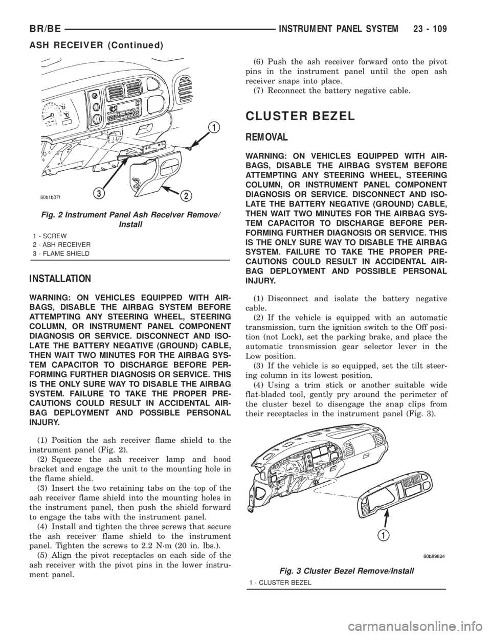
(1) Position the ash receiver flame shield to the
instrument panel (Fig. 2).
(2) Squeeze the ash receiver lamp and hood
bracket and engage the unit to the mounting hole in
the flame shield.
(3) Insert the two retaining tabs on the top of the
ash receiver flame shield into the mounting holes in
the instrument panel, then push the shield forward
to engage the tabs with the instrument panel.
(4) Install and tighten the three screws that secure
the ash receiver flame shield to the instrument
panel. Tighten the screws to 2.2 N´m (20 in. lbs.).
(5) Align the pivot receptacles on each side of the
ash receiver with the pivot pins in the lower instru-
ment panel.(6) Push the ash receiver forward onto the pivot
pins in the instrument panel until the open ash
receiver snaps into place.
(7) Reconnect the battery negative cable.
CLUSTER BEZEL
REMOVAL
WARNING: ON VEHICLES EQUIPPED WITH AIR-
BAGS, DISABLE THE AIRBAG SYSTEM BEFORE
ATTEMPTING ANY STEERING WHEEL, STEERING
COLUMN, OR INSTRUMENT PANEL COMPONENT
DIAGNOSIS OR SERVICE. DISCONNECT AND ISO-
LATE THE BATTERY NEGATIVE (GROUND) CABLE,
THEN WAIT TWO MINUTES FOR THE AIRBAG SYS-
TEM CAPACITOR TO DISCHARGE BEFORE PER-
FORMING FURTHER DIAGNOSIS OR SERVICE. THIS
IS THE ONLY SURE WAY TO DISABLE THE AIRBAG
SYSTEM. FAILURE TO TAKE THE PROPER PRE-
CAUTIONS COULD RESULT IN ACCIDENTAL AIR-
BAG DEPLOYMENT AND POSSIBLE PERSONAL
INJURY.
(1) Disconnect and isolate the battery negative
cable.
(2) If the vehicle is equipped with an automatic
transmission, turn the ignition switch to the Off posi-
tion (not Lock), set the parking brake, and place the
automatic transmission gear selector lever in the
Low position.
(3) If the vehicle is so equipped, set the tilt steer-
ing column in its lowest position.
(4) Using a trim stick or another suitable wide
flat-bladed tool, gently pry around the perimeter of
the cluster bezel to disengage the snap clips from
their receptacles in the instrument panel (Fig. 3).
Fig. 2 Instrument Panel Ash Receiver Remove/
Install
1 - SCREW
2 - ASH RECEIVER
3 - FLAME SHIELD
Fig. 3 Cluster Bezel Remove/Install
1 - CLUSTER BEZEL
BR/BEINSTRUMENT PANEL SYSTEM 23 - 109
ASH RECEIVER (Continued)
Page 2688 of 2889
(4) Remove the instrument panel from the vehicle.
(Refer to 23 - BODY/INSTRUMENT PANEL -
REMOVAL).
(5) Place the instrument panel on a suitable work
surface. Be certain to take the proper precautions to
protect the instrument panel from any possible cos-
metic damage.
(6) Remove the screws around the perimeter of the
top cover that secure it to the instrument panel
structural support, the defroster duct, and the demis-
ter ducts.
(7) Lift the top cover off of the instrument panel.
INSTALLATION
WARNING: ON VEHICLES EQUIPPED WITH AIR-
BAGS, DISABLE THE AIRBAG SYSTEM BEFORE
ATTEMPTING ANY STEERING WHEEL, STEERING
COLUMN, OR INSTRUMENT PANEL COMPONENT
DIAGNOSIS OR SERVICE. DISCONNECT AND ISO-
LATE THE BATTERY NEGATIVE (GROUND) CABLE,
THEN WAIT TWO MINUTES FOR THE AIRBAG SYS-
TEM CAPACITOR TO DISCHARGE BEFORE PER-
FORMING FURTHER DIAGNOSIS OR SERVICE. THIS
IS THE ONLY SURE WAY TO DISABLE THE AIRBAG
SYSTEM. FAILURE TO TAKE THE PROPER PRE-
CAUTIONS COULD RESULT IN ACCIDENTAL AIR-
BAG DEPLOYMENT AND POSSIBLE PERSONAL
INJURY.
(1) Position the top cover onto the instrument
panel.
(2) Install and tighten the screws around the
perimeter of the top cover that secure it to the
instrument panel structural support, the defroster
duct, and the demister ducts. Tighten the screws to
2.2 N´m (20 in. lbs.).
(3) Reinstall the instrument panel into the vehicle.
(Refer to 23 - BODY/INSTRUMENT PANEL -
INSTALLATION).
(4) Reinstall the passenger airbag into the instru-
ment panel. (Refer to 8 - ELECTRICAL/RE-
STRAINTS/PASSENGER AIRBAG -
INSTALLATION).
(5) Reinstall the cluster bezel onto the instrument
panel.(Refer to 23 - BODY/INSTRUMENT PANEL/
CLUSTER BEZEL - INSTALLATION).
(6) Reconnect the battery negative cable.
STEERING COLUMN OPENING
COVER
REMOVAL
WARNING: ON VEHICLES EQUIPPED WITH AIR-
BAGS, DISABLE THE AIRBAG SYSTEM BEFORE
ATTEMPTING ANY STEERING WHEEL, STEERING
COLUMN, OR INSTRUMENT PANEL COMPONENT
DIAGNOSIS OR SERVICE. DISCONNECT AND ISO-
LATE THE BATTERY NEGATIVE (GROUND) CABLE,
THEN WAIT TWO MINUTES FOR THE AIRBAG SYS-
TEM CAPACITOR TO DISCHARGE BEFORE PER-
FORMING FURTHER DIAGNOSIS OR SERVICE. THIS
IS THE ONLY SURE WAY TO DISABLE THE AIRBAG
SYSTEM. FAILURE TO TAKE THE PROPER PRE-
CAUTIONS COULD RESULT IN ACCIDENTAL AIR-
BAG DEPLOYMENT AND POSSIBLE PERSONAL
INJURY.
(1) Disconnect and isolate the battery negative
cable.
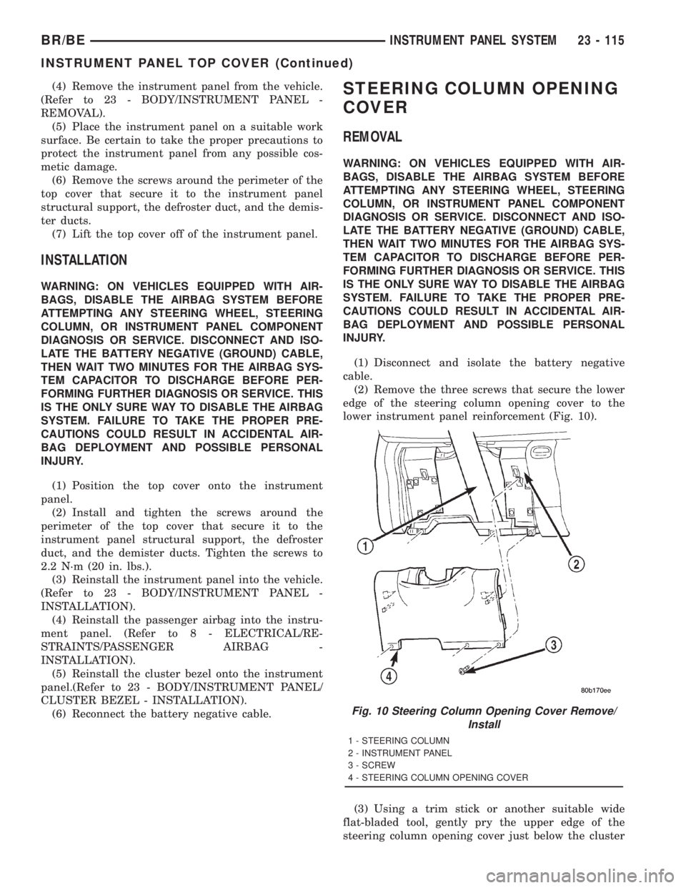
(2) Remove the three screws that secure the lower
edge of the steering column opening cover to the
lower instrument panel reinforcement (Fig. 10).
(3) Using a trim stick or another suitable wide
flat-bladed tool, gently pry the upper edge of the
steering column opening cover just below the cluster
Fig. 10 Steering Column Opening Cover Remove/
Install
1 - STEERING COLUMN
2 - INSTRUMENT PANEL
3 - SCREW
4 - STEERING COLUMN OPENING COVER
BR/BEINSTRUMENT PANEL SYSTEM 23 - 115
INSTRUMENT PANEL TOP COVER (Continued)
Page 2754 of 2889
motor speeds, but can only be turned off by selecting
the Off position with the heater-only or a/c heater
control switch knob.
OPERATION
The blower motor switch directs the blower motor
ground path through the mode control switch to the
blower motor resistor, or directly to ground, as
required to achieve the selected blower motor speed.
The blower motor switch cannot be repaired and, if
faulty or damaged, the entire heater-only or a/c
heater control unit must be replaced. The blower
motor switch knob is serviced separately.
DIAGNOSIS AND TESTING - BLOWER MOTOR
SWITCH
For circuit descriptions and diagrams, (Refer to
Appropriate Wiring Information).
WARNING: ON VEHICLES EQUIPPED WITH AIR-
BAGS, DISABLE THE AIRBAG SYSTEM BEFORE
ATTEMPTING ANY STEERING WHEEL, STEERING
COLUMN, OR INSTRUMENT PANEL COMPONENT
DIAGNOSIS OR SERVICE. DISCONNECT AND ISO-
LATE THE BATTERY NEGATIVE (GROUND) CABLE,
THEN WAIT TWO MINUTES FOR THE AIRBAG SYS-
TEM CAPACITOR TO DISCHARGE BEFORE PER-
FORMING FURTHER DIAGNOSIS OR SERVICE. THIS
IS THE ONLY SURE WAY TO DISABLE THE AIRBAG
SYSTEM. FAILURE TO TAKE THE PROPER PRE-
CAUTIONS COULD RESULT IN AN ACCIDENTAL
AIRBAG DEPLOYMENT AND POSSIBLE PERSONAL
INJURY.
(1) Check for battery voltage at the fuse in the
Power Distribution Center (PDC). If OK, go to Step
2. If not OK, repair the shorted circuit or component
as required and replace the faulty fuse.
(2) Turn the ignition switch to the Off position.
Disconnect and isolate the battery negative cable.
Remove the a/c heater control from the instrument
panel. (Refer to 24 - HEATING & AIR CONDITION-
ING/CONTROLS/A/C HEATER CONTROL -
REMOVAL) Check for continuity between the ground
circuit cavity of the a/c heater control wire harness
connector and a good ground. There should be conti-
nuity. If OK, go to Step 3. If not OK, repair the open
circuit to ground as required.
(3) With the a/c heater control wire harness con-
nector unplugged, place the a/c heater mode control
switch knob in any position except the Off position.
Check for continuity between the ground circuit ter-
minal and each of the blower motor driver circuit ter-
minals of the a/c heater control as you move the
blower motor switch knob to each of the four speed
positions. There should be continuity at each drivercircuit terminal in only one blower motor switch
speed position. If OK, test and repair the blower
driver circuits between the a/c heater control connec-
tor and the blower motor resistor as required. If not
OK, replace the faulty a/c heater control unit.
REMOVAL
The blower motor switch cannot be repaired and, if
faulty or damaged, the entire heater-only or a/c
heater control unit must be replaced. (Refer to 24 -
HEATING & AIR CONDITIONING/CONTROLS/A/C
HEATER CONTROL - REMOVAL) The blower motor
switch knob is serviced separately.
BLEND DOOR ACTUATOR
REMOVAL
WARNING: ON VEHICLES EQUIPPED WITH AIR-
BAGS, DISABLE THE AIRBAG SYSTEM BEFORE
ATTEMPTING ANY STEERING WHEEL, STEERING
COLUMN, OR INSTRUMENT PANEL COMPONENT
DIAGNOSIS OR SERVICE. DISCONNECT AND ISO-
LATE THE BATTERY NEGATIVE (GROUND) CABLE,
THEN WAIT TWO MINUTES FOR THE AIRBAG SYS-
TEM CAPACITOR TO DISCHARGE BEFORE PER-
FORMING FURTHER DIAGNOSIS OR SERVICE. THIS
IS THE ONLY SURE WAY TO DISABLE THE AIRBAG
SYSTEM. FAILURE TO TAKE THE PROPER PRE-
CAUTIONS COULD RESULT IN AN ACCIDENTAL
AIRBAG DEPLOYMENT AND POSSIBLE PERSONAL
INJURY.
(1) Turn the ignition switch to the run position.
(2) Locate the temperature control knob in the mid
(12 o'clock) position.
(3) Turn the ignition switch to the off position.
(4) Disconnect and isolate the battery negative
cable.
(5) Remove the instrument panel from the vehicle.
Refer to Instrument Panel System for the procedures.
(6) Remove the HVAC housing from the vehicle.
(Refer to 24 - HEATING & AIR CONDITIONING/
DISTRIBUTION/HVAC HOUSING - REMOVAL)
(7) Unplug the wire harness connector from the
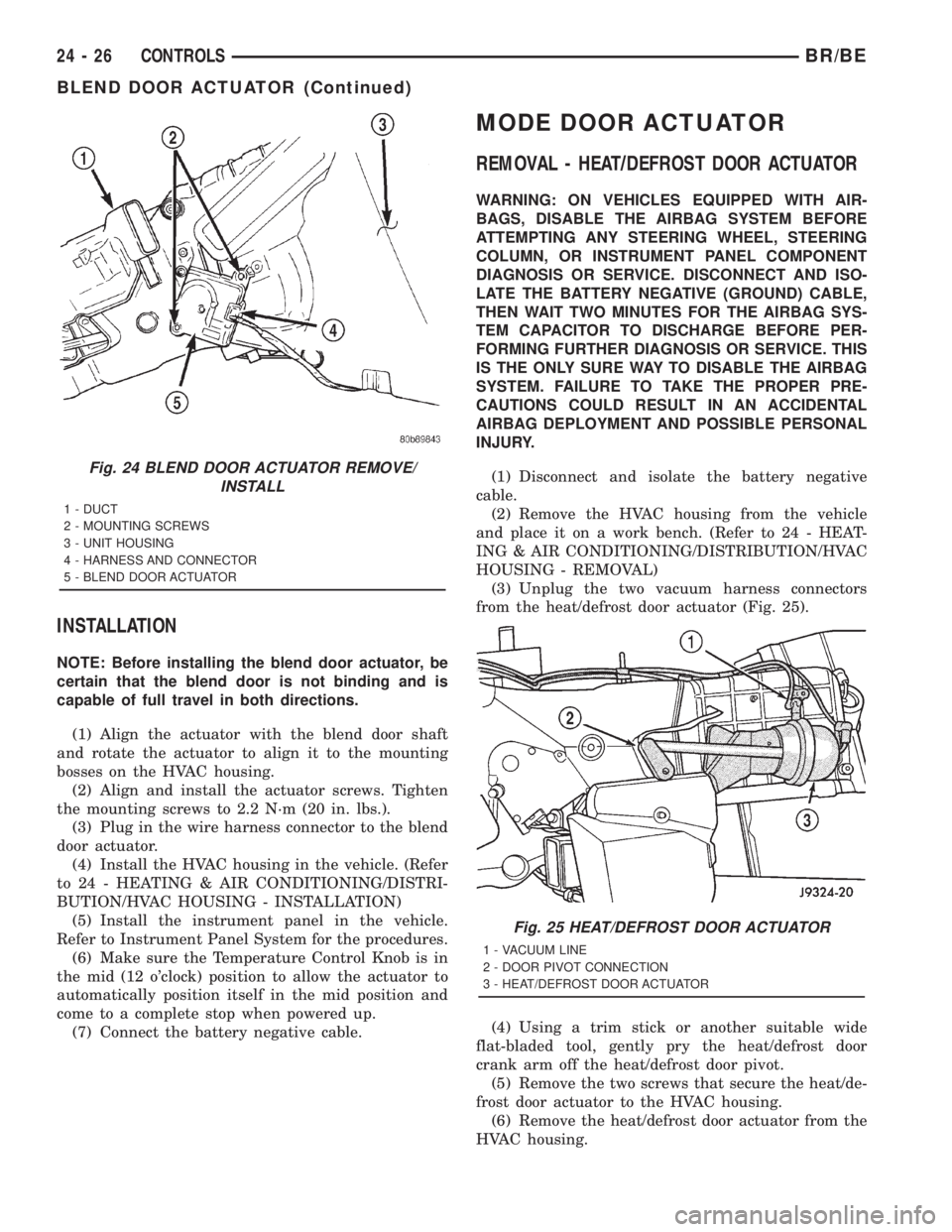
blend door actuator (Fig. 24).
(8) Remove the two mounting screws which secure
the actuator to the housing.
(9) Slide the blend door actuator off the blend door
shaft.
NOTE: A black plastic coupler may be attached to
the blend door shaft. Remove the coupler and
inspect for damage. Reinstall if there is no damage
found.
BR/BECONTROLS 24 - 25
BLOWER MOTOR SWITCH (Continued)
Page 2755 of 2889
INSTALLATION
NOTE: Before installing the blend door actuator, be
certain that the blend door is not binding and is
capable of full travel in both directions.
(1) Align the actuator with the blend door shaft
and rotate the actuator to align it to the mounting
bosses on the HVAC housing.
(2) Align and install the actuator screws. Tighten
the mounting screws to 2.2 N´m (20 in. lbs.).
(3) Plug in the wire harness connector to the blend
door actuator.
(4) Install the HVAC housing in the vehicle. (Refer
to 24 - HEATING & AIR CONDITIONING/DISTRI-
BUTION/HVAC HOUSING - INSTALLATION)
(5) Install the instrument panel in the vehicle.
Refer to Instrument Panel System for the procedures.
(6) Make sure the Temperature Control Knob is in
the mid (12 o'clock) position to allow the actuator to
automatically position itself in the mid position and
come to a complete stop when powered up.
(7) Connect the battery negative cable.
MODE DOOR ACTUATOR
REMOVAL - HEAT/DEFROST DOOR ACTUATOR
WARNING: ON VEHICLES EQUIPPED WITH AIR-
BAGS, DISABLE THE AIRBAG SYSTEM BEFORE
ATTEMPTING ANY STEERING WHEEL, STEERING
COLUMN, OR INSTRUMENT PANEL COMPONENT
DIAGNOSIS OR SERVICE. DISCONNECT AND ISO-
LATE THE BATTERY NEGATIVE (GROUND) CABLE,
THEN WAIT TWO MINUTES FOR THE AIRBAG SYS-
TEM CAPACITOR TO DISCHARGE BEFORE PER-
FORMING FURTHER DIAGNOSIS OR SERVICE. THIS
IS THE ONLY SURE WAY TO DISABLE THE AIRBAG
SYSTEM. FAILURE TO TAKE THE PROPER PRE-
CAUTIONS COULD RESULT IN AN ACCIDENTAL
AIRBAG DEPLOYMENT AND POSSIBLE PERSONAL
INJURY.
(1) Disconnect and isolate the battery negative
cable.
(2) Remove the HVAC housing from the vehicle
and place it on a work bench. (Refer to 24 - HEAT-
ING & AIR CONDITIONING/DISTRIBUTION/HVAC
HOUSING - REMOVAL)
(3) Unplug the two vacuum harness connectors
from the heat/defrost door actuator (Fig. 25).
(4) Using a trim stick or another suitable wide
flat-bladed tool, gently pry the heat/defrost door
crank arm off the heat/defrost door pivot.
(5) Remove the two screws that secure the heat/de-
frost door actuator to the HVAC housing.
(6) Remove the heat/defrost door actuator from the
HVAC housing.
Fig. 24 BLEND DOOR ACTUATOR REMOVE/
INSTALL
1 - DUCT
2 - MOUNTING SCREWS
3 - UNIT HOUSING
4 - HARNESS AND CONNECTOR
5 - BLEND DOOR ACTUATOR
Fig. 25 HEAT/DEFROST DOOR ACTUATOR
1 - VACUUM LINE
2 - DOOR PIVOT CONNECTION
3 - HEAT/DEFROST DOOR ACTUATOR
24 - 26 CONTROLSBR/BE
BLEND DOOR ACTUATOR (Continued)
Page 2756 of 2889
REMOVAL - PANEL/DEFROST DOOR
ACTUATOR
WARNING: ON VEHICLES EQUIPPED WITH AIRBAGS,
DISABLE THE AIRBAG SYSTEM BEFORE ATTEMPT-
ING ANY STEERING WHEEL, STEERING COLUMN, OR
INSTRUMENT PANEL COMPONENT DIAGNOSIS OR
SERVICE. DISCONNECT AND ISOLATE THE BATTERY
NEGATIVE (GROUND) CABLE, THEN WAIT TWO MIN-
UTES FOR THE AIRBAG SYSTEM CAPACITOR TO DIS-
CHARGE BEFORE PERFORMING FURTHER
DIAGNOSIS OR SERVICE. THIS IS THE ONLY SURE
WAY TO DISABLE THE AIRBAG SYSTEM. FAILURE TO
TAKE THE PROPER PRECAUTIONS COULD RESULT
IN AN ACCIDENTAL AIRBAG DEPLOYMENT AND POS-
SIBLE PERSONAL INJURY.
(1)Disconnect and isolate the battery negative cable.
(2) Remove the instrument panel assembly from
the vehicle. Refer to Instrument Panel System for the
procedures.
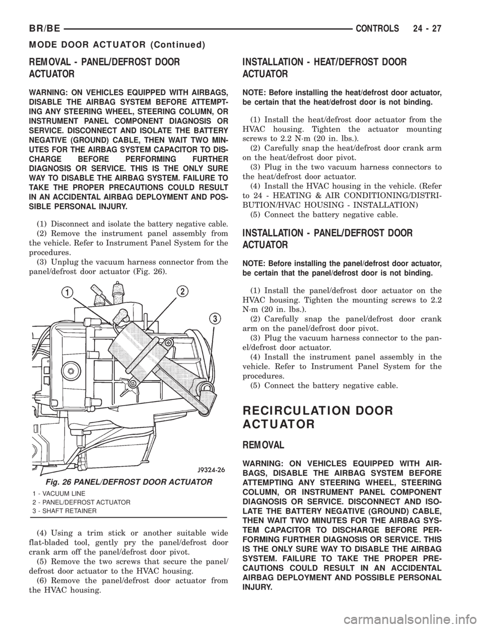
(3) Unplug the vacuum harness connector from the
panel/defrost door actuator (Fig. 26).
(4) Using a trim stick or another suitable wide
flat-bladed tool, gently pry the panel/defrost door
crank arm off the panel/defrost door pivot.
(5) Remove the two screws that secure the panel/
defrost door actuator to the HVAC housing.
(6) Remove the panel/defrost door actuator from
the HVAC housing.
INSTALLATION - HEAT/DEFROST DOOR
ACTUATOR
NOTE: Before installing the heat/defrost door actuator,
be certain that the heat/defrost door is not binding.
(1) Install the heat/defrost door actuator from the
HVAC housing. Tighten the actuator mounting
screws to 2.2 N´m (20 in. lbs.).
(2) Carefully snap the heat/defrost door crank arm
on the heat/defrost door pivot.
(3) Plug in the two vacuum harness connectors to
the heat/defrost door actuator.
(4) Install the HVAC housing in the vehicle. (Refer
to 24 - HEATING & AIR CONDITIONING/DISTRI-
BUTION/HVAC HOUSING - INSTALLATION)
(5) Connect the battery negative cable.
INSTALLATION - PANEL/DEFROST DOOR
ACTUATOR
NOTE: Before installing the panel/defrost door actuator,
be certain that the panel/defrost door is not binding.
(1) Install the panel/defrost door actuator on the
HVAC housing. Tighten the mounting screws to 2.2
N´m (20 in. lbs.).
(2) Carefully snap the panel/defrost door crank
arm on the panel/defrost door pivot.
(3) Plug the vacuum harness connector to the pan-
el/defrost door actuator.
(4) Install the instrument panel assembly in the
vehicle. Refer to Instrument Panel System for the
procedures.
(5) Connect the battery negative cable.
RECIRCULATION DOOR
ACTUATOR
REMOVAL
WARNING: ON VEHICLES EQUIPPED WITH AIR-
BAGS, DISABLE THE AIRBAG SYSTEM BEFORE
ATTEMPTING ANY STEERING WHEEL, STEERING
COLUMN, OR INSTRUMENT PANEL COMPONENT
DIAGNOSIS OR SERVICE. DISCONNECT AND ISO-
LATE THE BATTERY NEGATIVE (GROUND) CABLE,
THEN WAIT TWO MINUTES FOR THE AIRBAG SYS-
TEM CAPACITOR TO DISCHARGE BEFORE PER-
FORMING FURTHER DIAGNOSIS OR SERVICE. THIS
IS THE ONLY SURE WAY TO DISABLE THE AIRBAG
SYSTEM. FAILURE TO TAKE THE PROPER PRE-
CAUTIONS COULD RESULT IN AN ACCIDENTAL
AIRBAG DEPLOYMENT AND POSSIBLE PERSONAL
INJURY.
Fig. 26 PANEL/DEFROST DOOR ACTUATOR
1 - VACUUM LINE
2 - PANEL/DEFROST ACTUATOR
3 - SHAFT RETAINER
BR/BECONTROLS 24 - 27
MODE DOOR ACTUATOR (Continued)
Page 2761 of 2889
REMOVAL - PANEL OUTLET BARRELS
WARNING: THE PANEL OUTLET BARRELS
INSTALLED IN THE PASSENGER SIDE AIRBAG
DOOR PANEL OUTLET HOUSINGS MUST NEVER
BE REINSTALLED FOLLOWING REMOVAL FOR ANY
REASON. THEY MUST BE REPLACED WITH NEW
BARRELS. FAILURE TO OBSERVE THIS WARNING
COULD RESULT IN OCCUPANT INJURIES UPON
AIRBAG DEPLOYMENT.
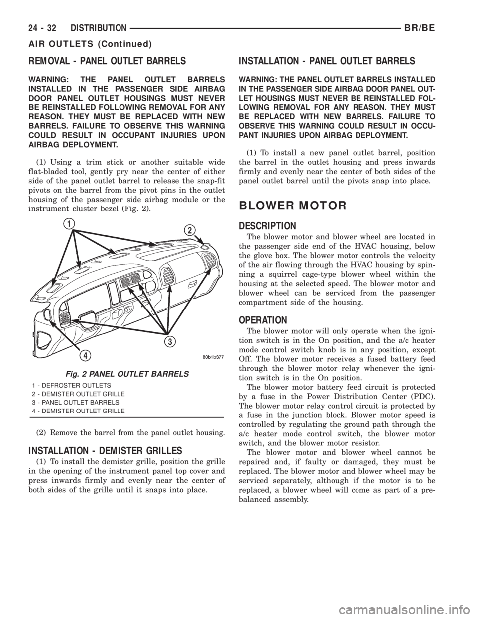
(1) Using a trim stick or another suitable wide
flat-bladed tool, gently pry near the center of either
side of the panel outlet barrel to release the snap-fit
pivots on the barrel from the pivot pins in the outlet
housing of the passenger side airbag module or the
instrument cluster bezel (Fig. 2).
(2)
Remove the barrel from the panel outlet housing.
INSTALLATION - DEMISTER GRILLES
(1) To install the demister grille, position the grille
in the opening of the instrument panel top cover and
press inwards firmly and evenly near the center of
both sides of the grille until it snaps into place.
INSTALLATION - PANEL OUTLET BARRELS
WARNING: THE PANEL OUTLET BARRELS INSTALLED
IN THE PASSENGER SIDE AIRBAG DOOR PANEL OUT-
LET HOUSINGS MUST NEVER BE REINSTALLED FOL-
LOWING REMOVAL FOR ANY REASON. THEY MUST
BE REPLACED WITH NEW BARRELS. FAILURE TO
OBSERVE THIS WARNING COULD RESULT IN OCCU-
PANT INJURIES UPON AIRBAG DEPLOYMENT.
(1) To install a new panel outlet barrel, position
the barrel in the outlet housing and press inwards
firmly and evenly near the center of both sides of the
panel outlet barrel until the pivots snap into place.
BLOWER MOTOR
DESCRIPTION
The blower motor and blower wheel are located in
the passenger side end of the HVAC housing, below
the glove box. The blower motor controls the velocity
of the air flowing through the HVAC housing by spin-
ning a squirrel cage-type blower wheel within the
housing at the selected speed. The blower motor and
blower wheel can be serviced from the passenger
compartment side of the housing.
OPERATION
The blower motor will only operate when the igni-
tion switch is in the On position, and the a/c heater
mode control switch knob is in any position, except
Off. The blower motor receives a fused battery feed
through the blower motor relay whenever the igni-
tion switch is in the On position.
The blower motor battery feed circuit is protected
by a fuse in the Power Distribution Center (PDC).
The blower motor relay control circuit is protected by
a fuse in the junction block. Blower motor speed is
controlled by regulating the ground path through the
a/c heater mode control switch, the blower motor
switch, and the blower motor resistor.
The blower motor and blower wheel cannot be
repaired and, if faulty or damaged, they must be
replaced. The blower motor and blower wheel may be
serviced separately, although if the motor is to be
replaced, a blower wheel will come as part of a pre-
balanced assembly.
Fig. 2 PANEL OUTLET BARRELS
1 - DEFROSTER OUTLETS
2 - DEMISTER OUTLET GRILLE
3 - PANEL OUTLET BARRELS
4 - DEMISTER OUTLET GRILLE
24 - 32 DISTRIBUTIONBR/BE
AIR OUTLETS (Continued)