2001 DODGE RAM transmission oil
[x] Cancel search: transmission oilPage 2544 of 2889
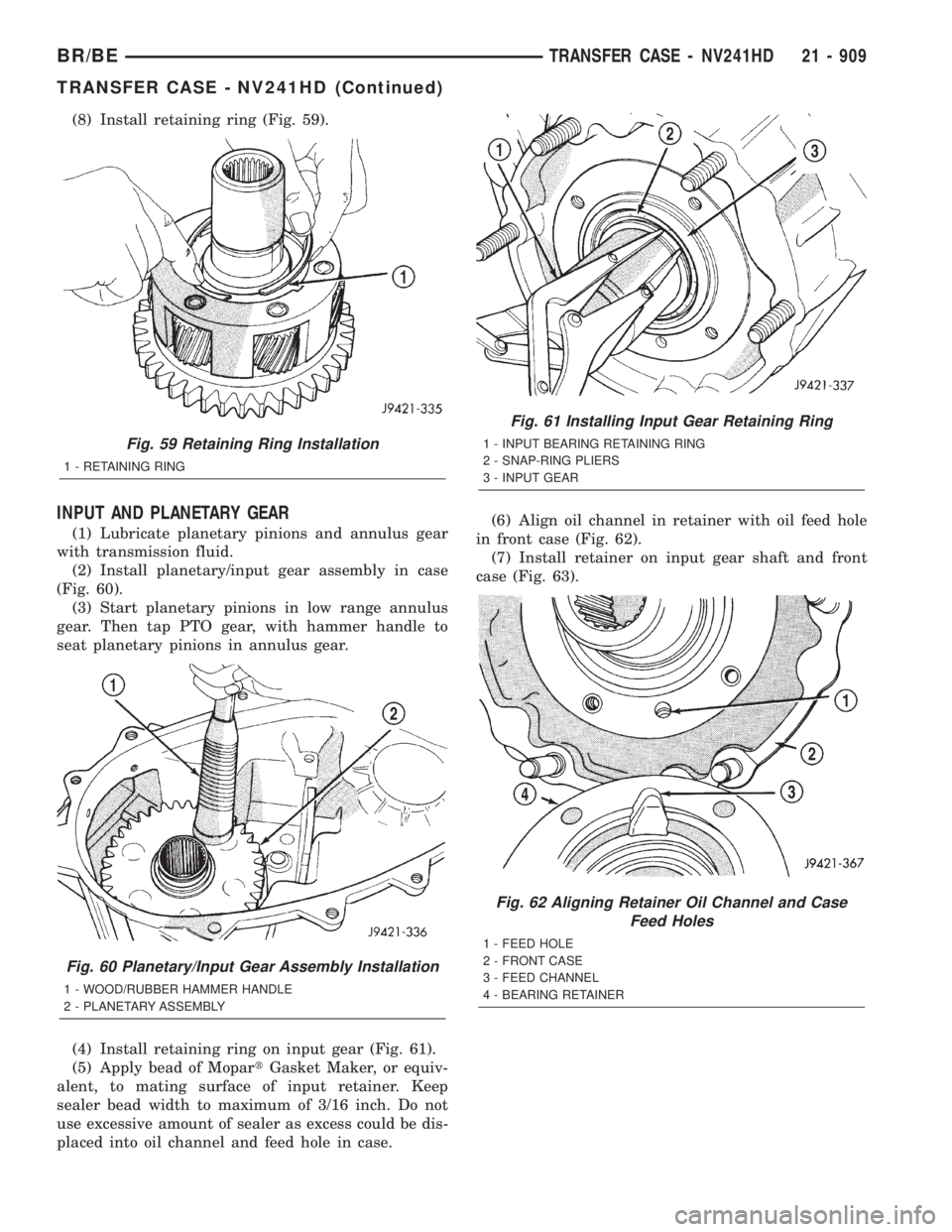
(8) Install retaining ring (Fig. 59).
INPUT AND PLANETARY GEAR
(1) Lubricate planetary pinions and annulus gear
with transmission fluid.
(2) Install planetary/input gear assembly in case
(Fig. 60).
(3) Start planetary pinions in low range annulus
gear. Then tap PTO gear, with hammer handle to
seat planetary pinions in annulus gear.
(4) Install retaining ring on input gear (Fig. 61).
(5) Apply bead of MopartGasket Maker, or equiv-
alent, to mating surface of input retainer. Keep
sealer bead width to maximum of 3/16 inch. Do not
use excessive amount of sealer as excess could be dis-
placed into oil channel and feed hole in case.(6) Align oil channel in retainer with oil feed hole
in front case (Fig. 62).
(7) Install retainer on input gear shaft and front
case (Fig. 63).
Fig. 59 Retaining Ring Installation
1 - RETAINING RING
Fig. 60 Planetary/Input Gear Assembly Installation
1 - WOOD/RUBBER HAMMER HANDLE
2 - PLANETARY ASSEMBLY
Fig. 61 Installing Input Gear Retaining Ring
1 - INPUT BEARING RETAINING RING
2 - SNAP-RING PLIERS
3 - INPUT GEAR
Fig. 62 Aligning Retainer Oil Channel and Case
Feed Holes
1 - FEED HOLE
2 - FRONT CASE
3 - FEED CHANNEL
4 - BEARING RETAINER
BR/BETRANSFER CASE - NV241HD 21 - 909
TRANSFER CASE - NV241HD (Continued)
Page 2554 of 2889
(7) Apply MopartSilicone Sealer to mating surface
of PTO cover and to cover bolt shanks and underside
of bolt heads. Then install and tighten bolts to 27-34
N´m (20-25 ft. lbs.) torque.
INSTALLATION
(1) Align and seat transfer case on transmission.
Be sure transfer case input gear splines are aligned
with transmission output shaft. Align splines by
rotating transfer case rear output shaft yoke if nec-
essary. Do not install any transfer case attaching
nuts until the transfer case is completely seated
against the transmission.
(2) Install and tighten transfer case attaching
nuts. Tighten nuts to 30-41 N´m (20-30 ft.lbs.).
(3) Install rear crossmember.(4) Remove jack stand from under transmission.
(5) Align and connect propeller shafts. (Refer to 3 -
DIFFERENTIAL & DRIVELINE/PROPELLER
SHAFT/PROPELLER SHAFT - INSTALLATION)
(6) Connect vacuum harness and vent hose.
(7) Connect shift rod to transfer case lever or floor
shift arm. Use channel lock style pliers to press rod
back into lever grommet.
(8) Adjust shift linkage, if necessary.
(9) Fill transfer case with recommended transmis-
sion fluid and install fill plug.
(10) Install skid plate, if equipped. (Refer to 13 -
FRAMES & BUMPERS/FRAME/TRANSFER CASE
SKID PLATE - INSTALLATION)
(11) Lower vehicle
SPECIFICATIONS
TRANSFER CASE
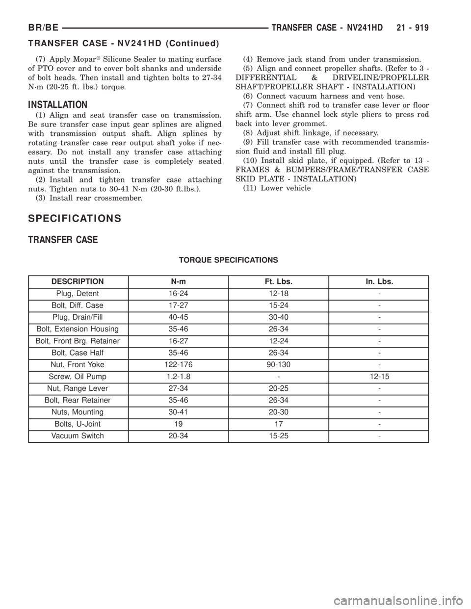
TORQUE SPECIFICATIONS
DESCRIPTION N-m Ft. Lbs. In. Lbs.
Plug, Detent 16-24 12-18 -
Bolt, Diff. Case 17-27 15-24 -
Plug, Drain/Fill 40-45 30-40 -
Bolt, Extension Housing 35-46 26-34 -
Bolt, Front Brg. Retainer 16-27 12-24 -
Bolt, Case Half 35-46 26-34 -
Nut, Front Yoke 122-176 90-130 -
Screw, Oil Pump 1.2-1.8 - 12-15
Nut, Range Lever 27-34 20-25 -
Bolt, Rear Retainer 35-46 26-34 -
Nuts, Mounting 30-41 20-30 -
Bolts, U-Joint 19 17 -
Vacuum Switch 20-34 15-25 -
BR/BETRANSFER CASE - NV241HD 21 - 919
TRANSFER CASE - NV241HD (Continued)
Page 2775 of 2889
STANDARD PROCEDURE - REFRIGERANT
SYSTEM CHARGE
WARNING: REVIEW THE WARNINGS AND CAU-
TIONS IN THE FRONT OF THIS SECTION BEFORE
PERFORMING THE FOLLOWING OPERATION.
(Refer to 24 - HEATING & AIR CONDITIONING/
PLUMBING - WARNING) (Refer to 24 - HEATING &
AIR CONDITIONING/PLUMBING - CAUTION)
After the refrigerant system has been tested for
leaks and evacuated, a refrigerant charge can be
injected into the system. (Refer to 24 - HEATING &
AIR CONDITIONING/PLUMBING - SPECIFICA-
TIONS - CHARGE CAPACITY)
A R-134a refrigerant recovery/recycling/charging
station that meets SAE Standard J2210 must be
used to charge the refrigerant system with R-134a
refrigerant. Refer to the operating instructions sup-
plied by the equipment manufacturer for proper care
and use of this equipment.
SPECIFICATIONS
SPECIFICATIONS
The R-134a refrigerant system charge capacity for
this vehicle is: 0.907 kilograms (32 ounces).
A/C COMPRESSOR
DESCRIPTION - A/C COMPRESSOR
The air conditioning system uses a Sanden
SD7H15 seven cylinder, reciprocating wobble plate-
type compressor on all models. This compressor has a
fixed displacement of 150 cubic centimeters (9.375
cubic inches), and has both the suction and discharge
ports located on the cylinder head. A label identifying
the use of R-134a refrigerant is located on the com-
pressor.
DESCRIPTION - HIGH PRESSURE RELIEF
VALVE
A high pressure relief valve is located on the com-
pressor cylinder head, which is at the rear of the
compressor. This mechanical valve is designed to
vent refrigerant from the system to protect against
damage to the compressor and other system compo-
nents, caused by condenser air flow restriction or an
overcharge of refrigerant.
OPERATION - A/C COMPRESSOR
The compressor is driven by the engine through an
electric clutch, drive pulley and belt arrangement.
The compressor is lubricated by refrigerant oil that iscirculated throughout the refrigerant system with the
refrigerant.
The compressor draws in low-pressure refrigerant
vapor from the evaporator through its suction port. It
then compresses the refrigerant into a high-pressure,
high-temperature refrigerant vapor, which is then
pumped to the condenser through the compressor dis-
charge port.
The compressor cannot be repaired. If faulty or
damaged, the entire compressor assembly must be
replaced. The compressor clutch, pulley and clutch
coil are available for service.
OPERATION - HIGH PRESSURE RELIEF VALVE
The high pressure relief valve vents the system
when a discharge pressure of 3445 to 4135 kPa (500
to 600 psi) or above is reached. The valve closes with
a minimum discharge pressure of 2756 kPa (400 psi)
is reached.
The high pressure relief valve vents only enough
refrigerant to reduce the system pressure, and then
re-seats itself. The majority of the refrigerant is con-
served in the system. If the valve vents refrigerant, it
does not mean the valve is faulty.
The high pressure relief valve is a factory-cali-
brated unit. The valve cannot be adjusted or
repaired, and must not be removed or otherwise dis-
turbed. The valve is only serviced as a part of the
compressor assembly.
DIAGNOSIS AND TESTING - A/C COMPRESSOR
When investigating an air conditioning related
noise, you must first know the conditions under
which the noise occurs. These conditions include:
weather, vehicle speed, transmission in gear or neu-
tral, engine speed, engine temperature, and any
other special conditions. Noises that develop during
air conditioning operation can often be misleading.
For example: What sounds like a failed front bearing
or connecting rod, may be caused by loose bolts, nuts,
mounting brackets, or a loose compressor clutch
assembly.
Drive belts are speed sensitive. At different engine
speeds and depending upon belt tension, belts can
develop noises that are mistaken for a compressor
noise. Improper belt tension can cause a misleading
noise when the compressor clutch is engaged, which
may not occur when the compressor clutch is disen-
gaged. Check the serpentine drive belt condition and
tension as described in Cooling before beginning this
procedure.
(1) Select a quiet area for testing. Duplicate the
complaint conditions as much as possible. Switch the
compressor on and off several times to clearly iden-
tify the compressor noise. Listen to the compressor
while the clutch is engaged and disengaged. Probe
24 - 46 PLUMBINGBR/BE
PLUMBING (Continued)
Page 2795 of 2889

(M)Malfunction Indicator Lamp (MIL) illuminated during engine operation if this DTC was recorded
(depending if required by CARB and/or EPA). MIL is displayed as an engine icon on instrument panel.
(G)Generator lamp illuminated
Generic Scan
Tool P-CodeDRB Scan Tool Display Brief Description of DTC
P0505 (M) Idle Air Control Motor Circuits SBEC II
P0522 Oil Pressure Voltage Too Low Oil pressure sending unit (sensor) voltage input below the
minimum acceptable voltage.
P0523 Oil Pressure Voltage Too High Oil pressure sending unit (sensor) voltage input above the
maximum acceptable voltage.
P0524 Oil Pressure Too Low Engine oil pressure is low. Engine power derated.
P0545 A/C Clutch Relay Circuit Problem detected in air conditioning clutch relay control
circuit.
P0551 Power Steering Switch Failure Incorrect input state detected for the power steering
switch circuit. PL: High pressure seen at high speed.
P0562 Charging System Voltage Too Low Supply voltage sensed at ECM too low.
P0563 Charging System Voltage Too High Supply voltage sensed at ECM too high.
P0600 PCM Failure SPI Communications No communication detected between co-processors in the
control module.
P0601 (M) Internal Controller Failure Internal control module fault condition (check sum)
detected.
P0602 (M) ECM Fueling Calibration Error ECM Internal fault condition detected.
P0604 RAM Check Failure Transmission control module RAM self test fault detected.
-Aisin transmission
P0605 ROM Check Falure Transmission control module ROM self test fault detected
-Aisin transmission
P0606 (M) ECM Failure ECM Internal fault condition detected.
P0615 Starter Relay Control Circuit An open or shorted condition detected in the starter relay
control circuit.
P0622 (G) Generator Field Not Switching
ProperlyAn open or shorted condition detected in the generator
field control circuit.
P0645 A/C Clutch Relay Circuit An open or shorted condition detected in the A/C clutch
relay control circuit.
P0700 EATX Controller DTC Present This SBEC III or JTEC DTC indicates that the EATX or
Aisin controller has an active fault and has illuminated the
MIL via a CCD (EATX) or SCI (Aisin) message. The
specific fault must be acquired from the EATX via CCD or
from the Aisin via ISO-9141.
P0703 Brake Switch Stuck Pressed or
ReleasedIncorrect input state detected in the brake switch circuit.
(Changed from P1595)
P0711 (M) Trans Temp Sensor, No Temp Rise
After StartRelationship between the transmission temperature and
overdrive operation and/or TCC operation indicates a
failure of the Transmission Temperature Sensor. OBD II
Rationality. Was MIL code 37.
P0712 Trans Temp Sensor Voltage Too Low Transmission fluid temperature sensor input below
acceptable voltage. Was MIL code 37.
P0712 (M) Trans Temp Sensor Voltage Too Low Voltage less than 1.55 volts (4-speed auto. trans. only).
25 - 8 EMISSIONS CONTROLBR/BE
EMISSIONS CONTROL (Continued)
Page 2828 of 2889
Items found requiring adjustment and/or repair
should be corrected before delivery of the vehicle.
NOTE: It is the dealer's responsibility to protect
new vehicles from damage and deterioration prior
to retail delivery both before and after new vehicle
preparation.
The information includes the following features:
Inspection points are cross-referenced to the New
Vehicle Preparation Form as follows:
²Titles indicate the general area being inspected
or the types of checks being made (i.e., underhood,
body-exterior, road test, etc.).
²Sub-Titles identify the types of items to be
inspected in that area (i.e., lines/hoses, wiring, etc.).
Procedures follow a logical order to prevent dupli-
cation and wasted effort.
Tips to help you do a better job are found as
NOTES.
RECEIVING
INSPECTION
The following procedures are recommended for
your own protection upon receipt of new vehicles.
When a new car is delivered by the carrier, it should
be inspected to ensure that it is in good condition
and to determine if there is any shortage or transpor-
tation damage.
EXTERIOR
Upon receipt of a new vehicle, check immediately
for:
²Under carriage damage
²Chipped or cracked windshield, broken windows,
and loose or missing moldings and name-plates
²Dents, scrapes, scratches, chips, dirt in paints or
other damage to the body exterior
²Damaged or missing side view mirror(s)
²Missing wheel nuts
²Broken or missing lenses
²Chafing, bruises, cuts, or scrapes on tire side-
walls or tread
²Missing underhood items
²Missing fuel filler cap
²Shipped loose items-license plate bracket, spare
tire, jack and tire wrench, radio antenna, floor mats,
wheel covers, cargo nets, fuses and other items²Ensure that IOD fuse is removed
²Check battery test indicator when easily visible,
or use voltmeter (battery must be at 12.4 volts or
greater). Charge to ensure green dot-visibility, per-
manent damage may occur if battery remains in a
discharged state for any length of time.
INTERIOR
Check interior items such as:
²Rearview mirror
²Accessory control knobs
²Smokers package items
²Keys
²Radio
²Special equipment items listed on shipper
²Owner's Manual and Consumer information Bro-
chures (normally stored in the glove box).
²Cuts, abrasions or stains on interior trim.
NOTE: Remember a careful look at new vehicles
when they are received may prevent problems when
preparing vehicles for delivery to your customers.
MAJOR INSPECTION POINTS
(1) Check operation of hood latch and safety catch-
adjust as required.
(2) Check all fluids for proper level and top off
with the proper fluid as required-engine oil, auto-
matic transmission fluid, brake master cylinder,
clutch master cylinder, power steering, windshield
washer, and cooling system. (Vehicle must be at nor-
mal operating temperature for some of these checks.)
(3) Check brake, clutch, fuel, and power steering
lines and hoses for leaks and clearance from moving
and hot objects-reroute to the proper location and
tighten as required.
(4) Check battery state of charge-recharge if neces-
sary, to ensure green dot is visible or instrument
panel voltmeter indicates 12.4 volts or greater.
(5) Check routing and connections of underhood
wiring, vacuum hoses, refrigerant lines and coolant
hoses for leaks, loose connections and clearance from
moving objects reroute and tighten connections as
required. Install IOD fuse on applicable vehicles.
NOTE: Reset radio, clock, compass, etc., after
installing, if vehicle is being delivered.
BR/BENEW VEHICLE PREPARATION 30 - 3
INTRODUCTION (Continued)
Page 2829 of 2889
UNDER HOOD
INSPECTION - HOOD LATCH/SAFETY CATCH
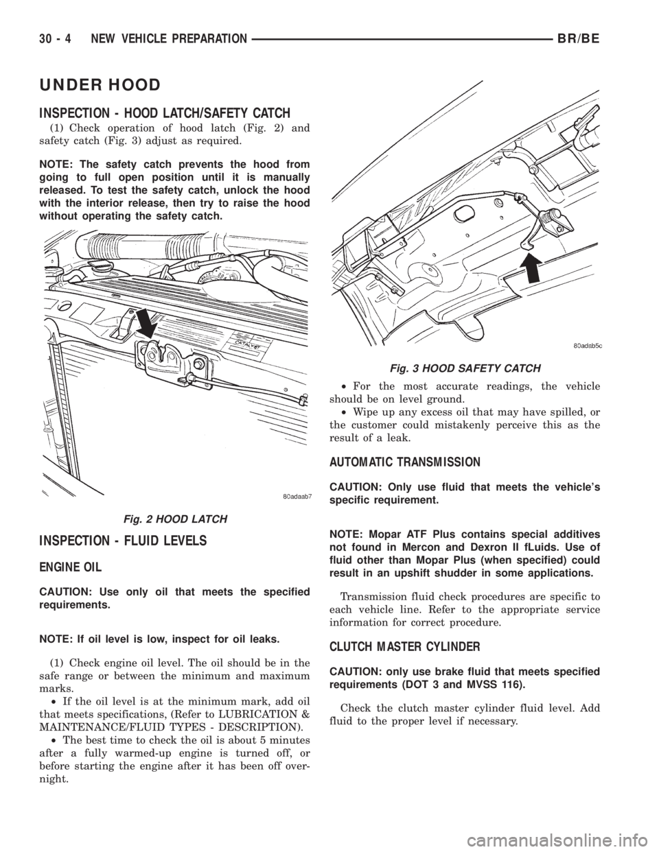
(1) Check operation of hood latch (Fig. 2) and
safety catch (Fig. 3) adjust as required.
NOTE: The safety catch prevents the hood from
going to full open position until it is manually
released. To test the safety catch, unlock the hood
with the interior release, then try to raise the hood
without operating the safety catch.
INSPECTION - FLUID LEVELS
ENGINE OIL
CAUTION: Use only oil that meets the specified
requirements.
NOTE: If oil level is low, inspect for oil leaks.
(1) Check engine oil level. The oil should be in the
safe range or between the minimum and maximum
marks.
²If the oil level is at the minimum mark, add oil
that meets specifications, (Refer to LUBRICATION &
MAINTENANCE/FLUID TYPES - DESCRIPTION).
²The best time to check the oil is about 5 minutes
after a fully warmed-up engine is turned off, or
before starting the engine after it has been off over-
night.²For the most accurate readings, the vehicle
should be on level ground.
²Wipe up any excess oil that may have spilled, or
the customer could mistakenly perceive this as the
result of a leak.
AUTOMATIC TRANSMISSION
CAUTION: Only use fluid that meets the vehicle's
specific requirement.
NOTE: Mopar ATF Plus contains special additives
not found in Mercon and Dexron II fLuids. Use of
fluid other than Mopar Plus (when specified) could
result in an upshift shudder in some applications.
Transmission fluid check procedures are specific to
each vehicle line. Refer to the appropriate service
information for correct procedure.
CLUTCH MASTER CYLINDER
CAUTION: only use brake fluid that meets specified
requirements (DOT 3 and MVSS 116).
Check the clutch master cylinder fluid level. Add
fluid to the proper level if necessary.
Fig. 2 HOOD LATCH
Fig. 3 HOOD SAFETY CATCH
30 - 4 NEW VEHICLE PREPARATIONBR/BE
Page 2831 of 2889
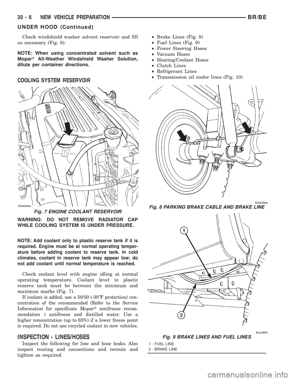
Check windshield washer solvent reservoir and fill
as necessary (Fig. 6).
NOTE: When using concentrated solvent such as
MoparTAll-Weather Windshield Washer Solution,
dilute per container directions.
COOLING SYSTEM RESERVOIR
WARNING: DO NOT REMOVE RADIATOR CAP
WHILE COOLING SYSTEM IS UNDER PRESSURE.
NOTE: Add coolant only to plastic reserve tank if it is
required. Engine must be at normal operating temper-
ature before adding coolant to reserve tank. In cold
climates, coolant in reserve tank may appear low; do
not add coolant until normal temperature is reached.
Check coolant level with engine idling at normal
operating temperature. Coolant level in plastic
reserve tank must be between the minimum and
maximun marks (Fig. 7).
If coolant is added, use a 50/50 (-309F protection) con-
centration of the recommended (Refer to the Service
Information for specificate Mopartantifreeze recom-
mendation ) antifreeze and distilled water. Use a
higher concentration (up to 65%) if a lower freeze point
is required. Do not use recycled coolant in new vehicles.
INSPECTION - LINES/HOSES
Inspect the following for line and hose leaks. Also
inspect routing and connections and reroute and
tighten as required.²Brake Lines (Fig. 8)
²Fuel Lines (Fig. 9)
²Power Steering Hoses
²Vacuum Hoses
²Heating/Coolant Hoses
²Clutch Lines
²Refrigerant Lines
²Transmission oil cooler lines (Fig. 10)
Fig. 7 ENGINE COOLANT RESERVOIRFig. 8 PARKING BRAKE CABLE AND BRAKE LINE
Fig. 9 BRAKE LINES AND FUEL LINES
1 - FUEL LINE
2 - BRAKE LINE
30 - 6 NEW VEHICLE PREPARATIONBR/BE
UNDER HOOD (Continued)
Page 2832 of 2889
INSPECTION - BATTERY
When battery is easily accessible, check the test
indicator (green dot), terminal tightness and felt
(grease) washer on battery posts. Recharge battery as
required to assure that the green dot is visible.
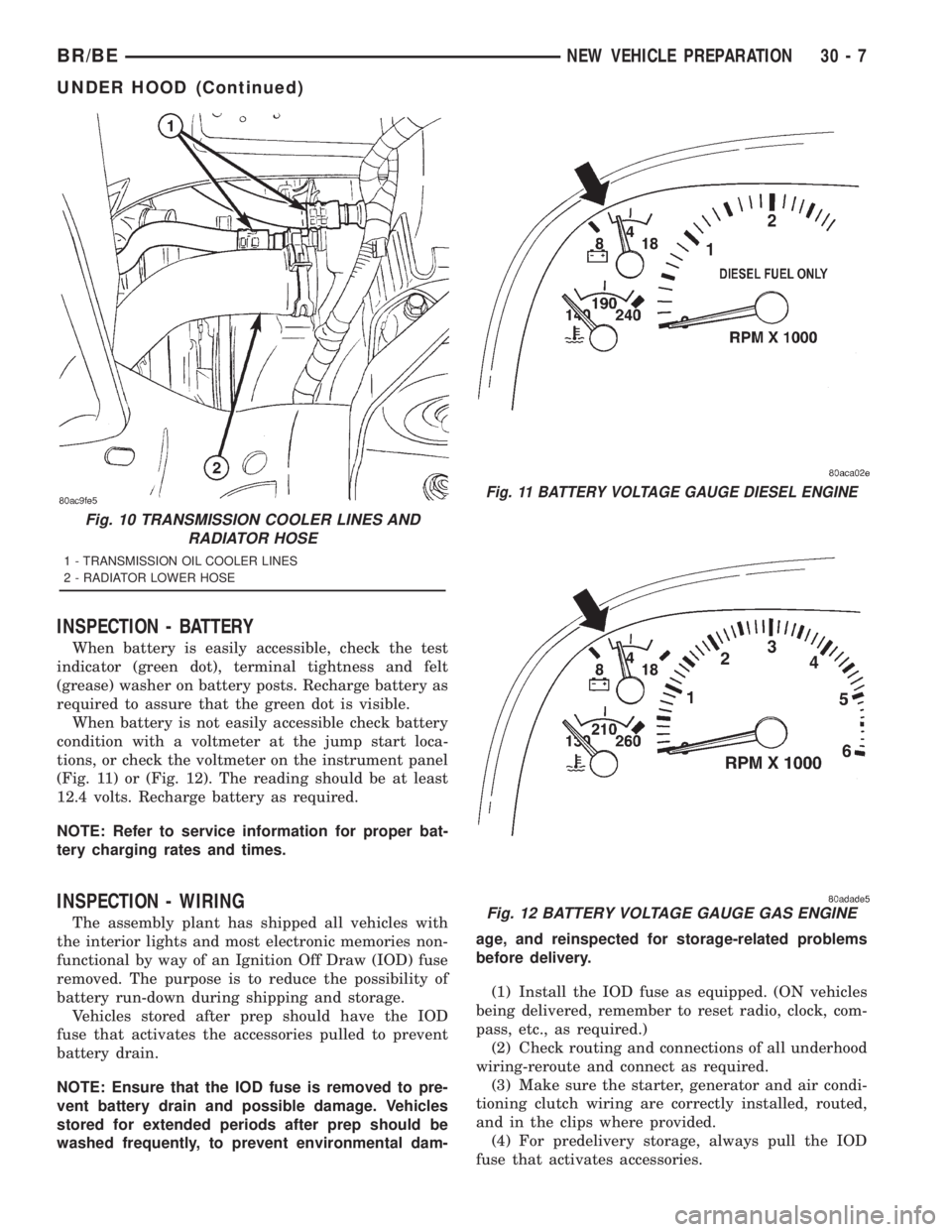
When battery is not easily accessible check battery
condition with a voltmeter at the jump start loca-
tions, or check the voltmeter on the instrument panel
(Fig. 11) or (Fig. 12). The reading should be at least
12.4 volts. Recharge battery as required.
NOTE: Refer to service information for proper bat-
tery charging rates and times.
INSPECTION - WIRING
The assembly plant has shipped all vehicles with
the interior lights and most electronic memories non-
functional by way of an Ignition Off Draw (IOD) fuse
removed. The purpose is to reduce the possibility of
battery run-down during shipping and storage.
Vehicles stored after prep should have the IOD
fuse that activates the accessories pulled to prevent
battery drain.
NOTE: Ensure that the IOD fuse is removed to pre-
vent battery drain and possible damage. Vehicles
stored for extended periods after prep should be
washed frequently, to prevent environmental dam-age, and reinspected for storage-related problems
before delivery.
(1) Install the IOD fuse as equipped. (ON vehicles
being delivered, remember to reset radio, clock, com-
pass, etc., as required.)
(2) Check routing and connections of all underhood
wiring-reroute and connect as required.
(3) Make sure the starter, generator and air condi-
tioning clutch wiring are correctly installed, routed,
and in the clips where provided.
(4) For predelivery storage, always pull the IOD
fuse that activates accessories.
Fig. 10 TRANSMISSION COOLER LINES AND
RADIATOR HOSE
1 - TRANSMISSION OIL COOLER LINES
2 - RADIATOR LOWER HOSE
Fig. 11 BATTERY VOLTAGE GAUGE DIESEL ENGINE
Fig. 12 BATTERY VOLTAGE GAUGE GAS ENGINE
BR/BENEW VEHICLE PREPARATION 30 - 7
UNDER HOOD (Continued)