2001 DODGE RAM check oil
[x] Cancel search: check oilPage 2786 of 2889
container immediately to prevent moisture contami-
nation.
STANDARD PROCEDURE - REFRIGERANT OIL
LEVEL
When an air conditioning system is assembled at
the factory, all components except the compressor are
refrigerant oil free. After the refrigerant system has
been charged and operated, the refrigerant oil in the
compressor is dispersed throughout the refrigerant
system. The accumulator, evaporator, condenser, and
compressor will each retain a significant amount of
the needed refrigerant oil.
It is important to have the correct amount of oil in
the refrigerant system. This ensures proper lubrica-
tion of the compressor. Too little oil will result in
damage to the compressor. Too much oil will reduce
the cooling capacity of the air conditioning system.
It will not be necessary to check the oil level in the
compressor or to add oil, unless there has been an oil
loss. An oil loss may occur due to a rupture or leak
from a refrigerant line, a connector fitting, a compo-
nent, or a component seal. If a leak occurs, add 30
milliliters (1 fluid ounce) of refrigerant oil to the
refrigerant system after the repair has been made.Refrigerant oil loss will be evident at the leak point
by the presence of a wet, shiny surface around the
leak.
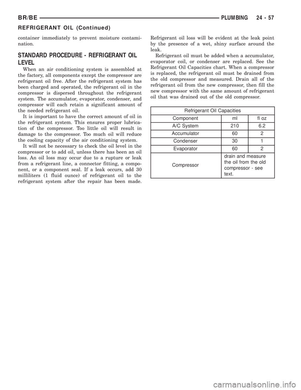
Refrigerant oil must be added when a accumulator,
evaporator coil, or condenser are replaced. See the
Refrigerant Oil Capacities chart. When a compressor
is replaced, the refrigerant oil must be drained from
the old compressor and measured. Drain all of the
refrigerant oil from the new compressor, then fill the
new compressor with the same amount of refrigerant
oil that was drained out of the old compressor.
Refrigerant Oil Capacities
Component ml fl oz
A/C System 210 6.2
Accumulator 60 2
Condenser 30 1
Evaporator 60 2
Compressordrain and measure
the oil from the old
compressor - see
text.
BR/BEPLUMBING 24 - 57
REFRIGERANT OIL (Continued)
Page 2795 of 2889

(M)Malfunction Indicator Lamp (MIL) illuminated during engine operation if this DTC was recorded
(depending if required by CARB and/or EPA). MIL is displayed as an engine icon on instrument panel.
(G)Generator lamp illuminated
Generic Scan
Tool P-CodeDRB Scan Tool Display Brief Description of DTC
P0505 (M) Idle Air Control Motor Circuits SBEC II
P0522 Oil Pressure Voltage Too Low Oil pressure sending unit (sensor) voltage input below the
minimum acceptable voltage.
P0523 Oil Pressure Voltage Too High Oil pressure sending unit (sensor) voltage input above the
maximum acceptable voltage.
P0524 Oil Pressure Too Low Engine oil pressure is low. Engine power derated.
P0545 A/C Clutch Relay Circuit Problem detected in air conditioning clutch relay control
circuit.
P0551 Power Steering Switch Failure Incorrect input state detected for the power steering
switch circuit. PL: High pressure seen at high speed.
P0562 Charging System Voltage Too Low Supply voltage sensed at ECM too low.
P0563 Charging System Voltage Too High Supply voltage sensed at ECM too high.
P0600 PCM Failure SPI Communications No communication detected between co-processors in the
control module.
P0601 (M) Internal Controller Failure Internal control module fault condition (check sum)
detected.
P0602 (M) ECM Fueling Calibration Error ECM Internal fault condition detected.
P0604 RAM Check Failure Transmission control module RAM self test fault detected.
-Aisin transmission
P0605 ROM Check Falure Transmission control module ROM self test fault detected
-Aisin transmission
P0606 (M) ECM Failure ECM Internal fault condition detected.
P0615 Starter Relay Control Circuit An open or shorted condition detected in the starter relay
control circuit.
P0622 (G) Generator Field Not Switching
ProperlyAn open or shorted condition detected in the generator
field control circuit.
P0645 A/C Clutch Relay Circuit An open or shorted condition detected in the A/C clutch
relay control circuit.
P0700 EATX Controller DTC Present This SBEC III or JTEC DTC indicates that the EATX or
Aisin controller has an active fault and has illuminated the
MIL via a CCD (EATX) or SCI (Aisin) message. The
specific fault must be acquired from the EATX via CCD or
from the Aisin via ISO-9141.
P0703 Brake Switch Stuck Pressed or
ReleasedIncorrect input state detected in the brake switch circuit.
(Changed from P1595)
P0711 (M) Trans Temp Sensor, No Temp Rise
After StartRelationship between the transmission temperature and
overdrive operation and/or TCC operation indicates a
failure of the Transmission Temperature Sensor. OBD II
Rationality. Was MIL code 37.
P0712 Trans Temp Sensor Voltage Too Low Transmission fluid temperature sensor input below
acceptable voltage. Was MIL code 37.
P0712 (M) Trans Temp Sensor Voltage Too Low Voltage less than 1.55 volts (4-speed auto. trans. only).
25 - 8 EMISSIONS CONTROLBR/BE
EMISSIONS CONTROL (Continued)
Page 2815 of 2889
SPECIFICATIONS
TORQUE - AIR INJECTION SYSTEM
DESCRIPTION N´m Ft. Lbs. In. Lbs.
Air Pump Filter Housing
Nut18
Air Pump Mounting Bolts 40 30
Air Pump Pulley Mounting
Bolts11 105
One-Way Check Valve to
Catalyst Tube33 25
AIR INJECTION PUMP
DESCRIPTION
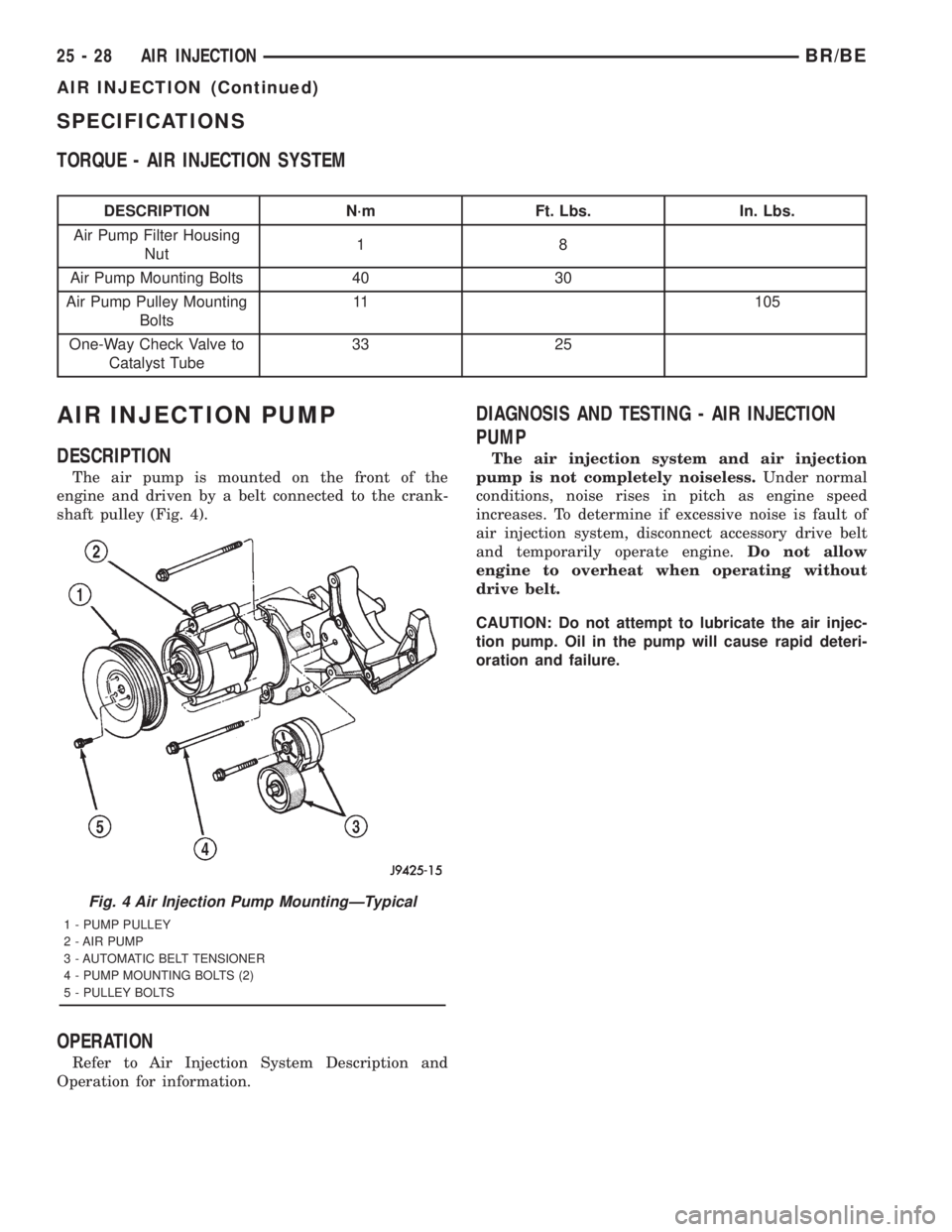
The air pump is mounted on the front of the
engine and driven by a belt connected to the crank-
shaft pulley (Fig. 4).
OPERATION
Refer to Air Injection System Description and
Operation for information.
DIAGNOSIS AND TESTING - AIR INJECTION
PUMP
The air injection system and air injection
pump is not completely noiseless.Under normal
conditions, noise rises in pitch as engine speed
increases. To determine if excessive noise is fault of
air injection system, disconnect accessory drive belt
and temporarily operate engine.Do not allow
engine to overheat when operating without
drive belt.
CAUTION: Do not attempt to lubricate the air injec-
tion pump. Oil in the pump will cause rapid deteri-
oration and failure.
Fig. 4 Air Injection Pump MountingÐTypical
1 - PUMP PULLEY
2 - AIR PUMP
3 - AUTOMATIC BELT TENSIONER
4 - PUMP MOUNTING BOLTS (2)
5 - PULLEY BOLTS
25 - 28 AIR INJECTIONBR/BE
AIR INJECTION (Continued)
Page 2828 of 2889
Items found requiring adjustment and/or repair
should be corrected before delivery of the vehicle.
NOTE: It is the dealer's responsibility to protect
new vehicles from damage and deterioration prior
to retail delivery both before and after new vehicle
preparation.
The information includes the following features:
Inspection points are cross-referenced to the New
Vehicle Preparation Form as follows:
²Titles indicate the general area being inspected
or the types of checks being made (i.e., underhood,
body-exterior, road test, etc.).
²Sub-Titles identify the types of items to be
inspected in that area (i.e., lines/hoses, wiring, etc.).
Procedures follow a logical order to prevent dupli-
cation and wasted effort.
Tips to help you do a better job are found as
NOTES.
RECEIVING
INSPECTION
The following procedures are recommended for
your own protection upon receipt of new vehicles.
When a new car is delivered by the carrier, it should
be inspected to ensure that it is in good condition
and to determine if there is any shortage or transpor-
tation damage.
EXTERIOR
Upon receipt of a new vehicle, check immediately
for:
²Under carriage damage
²Chipped or cracked windshield, broken windows,
and loose or missing moldings and name-plates
²Dents, scrapes, scratches, chips, dirt in paints or
other damage to the body exterior
²Damaged or missing side view mirror(s)
²Missing wheel nuts
²Broken or missing lenses
²Chafing, bruises, cuts, or scrapes on tire side-
walls or tread
²Missing underhood items
²Missing fuel filler cap
²Shipped loose items-license plate bracket, spare
tire, jack and tire wrench, radio antenna, floor mats,
wheel covers, cargo nets, fuses and other items²Ensure that IOD fuse is removed
²Check battery test indicator when easily visible,
or use voltmeter (battery must be at 12.4 volts or
greater). Charge to ensure green dot-visibility, per-
manent damage may occur if battery remains in a
discharged state for any length of time.
INTERIOR
Check interior items such as:
²Rearview mirror
²Accessory control knobs
²Smokers package items
²Keys
²Radio
²Special equipment items listed on shipper
²Owner's Manual and Consumer information Bro-
chures (normally stored in the glove box).
²Cuts, abrasions or stains on interior trim.
NOTE: Remember a careful look at new vehicles
when they are received may prevent problems when
preparing vehicles for delivery to your customers.
MAJOR INSPECTION POINTS
(1) Check operation of hood latch and safety catch-
adjust as required.
(2) Check all fluids for proper level and top off
with the proper fluid as required-engine oil, auto-
matic transmission fluid, brake master cylinder,
clutch master cylinder, power steering, windshield
washer, and cooling system. (Vehicle must be at nor-
mal operating temperature for some of these checks.)
(3) Check brake, clutch, fuel, and power steering
lines and hoses for leaks and clearance from moving
and hot objects-reroute to the proper location and
tighten as required.
(4) Check battery state of charge-recharge if neces-
sary, to ensure green dot is visible or instrument
panel voltmeter indicates 12.4 volts or greater.
(5) Check routing and connections of underhood
wiring, vacuum hoses, refrigerant lines and coolant
hoses for leaks, loose connections and clearance from
moving objects reroute and tighten connections as
required. Install IOD fuse on applicable vehicles.
NOTE: Reset radio, clock, compass, etc., after
installing, if vehicle is being delivered.
BR/BENEW VEHICLE PREPARATION 30 - 3
INTRODUCTION (Continued)
Page 2829 of 2889
UNDER HOOD
INSPECTION - HOOD LATCH/SAFETY CATCH
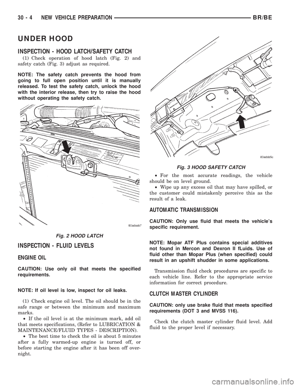
(1) Check operation of hood latch (Fig. 2) and
safety catch (Fig. 3) adjust as required.
NOTE: The safety catch prevents the hood from
going to full open position until it is manually
released. To test the safety catch, unlock the hood
with the interior release, then try to raise the hood
without operating the safety catch.
INSPECTION - FLUID LEVELS
ENGINE OIL
CAUTION: Use only oil that meets the specified
requirements.
NOTE: If oil level is low, inspect for oil leaks.
(1) Check engine oil level. The oil should be in the
safe range or between the minimum and maximum
marks.
²If the oil level is at the minimum mark, add oil
that meets specifications, (Refer to LUBRICATION &
MAINTENANCE/FLUID TYPES - DESCRIPTION).
²The best time to check the oil is about 5 minutes
after a fully warmed-up engine is turned off, or
before starting the engine after it has been off over-
night.²For the most accurate readings, the vehicle
should be on level ground.
²Wipe up any excess oil that may have spilled, or
the customer could mistakenly perceive this as the
result of a leak.
AUTOMATIC TRANSMISSION
CAUTION: Only use fluid that meets the vehicle's
specific requirement.
NOTE: Mopar ATF Plus contains special additives
not found in Mercon and Dexron II fLuids. Use of
fluid other than Mopar Plus (when specified) could
result in an upshift shudder in some applications.
Transmission fluid check procedures are specific to
each vehicle line. Refer to the appropriate service
information for correct procedure.
CLUTCH MASTER CYLINDER
CAUTION: only use brake fluid that meets specified
requirements (DOT 3 and MVSS 116).
Check the clutch master cylinder fluid level. Add
fluid to the proper level if necessary.
Fig. 2 HOOD LATCH
Fig. 3 HOOD SAFETY CATCH
30 - 4 NEW VEHICLE PREPARATIONBR/BE
Page 2831 of 2889
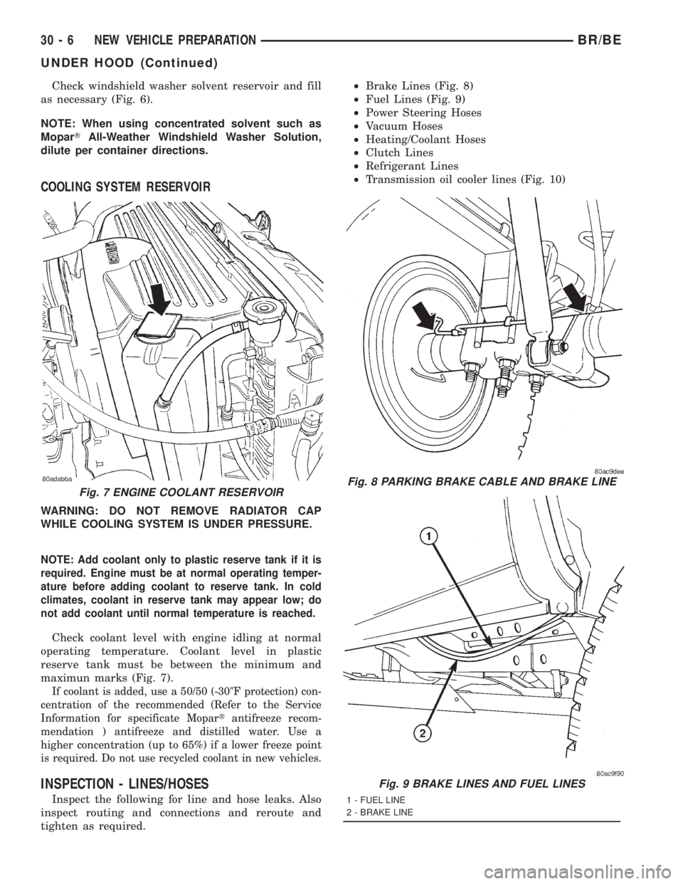
Check windshield washer solvent reservoir and fill
as necessary (Fig. 6).
NOTE: When using concentrated solvent such as
MoparTAll-Weather Windshield Washer Solution,
dilute per container directions.
COOLING SYSTEM RESERVOIR
WARNING: DO NOT REMOVE RADIATOR CAP
WHILE COOLING SYSTEM IS UNDER PRESSURE.
NOTE: Add coolant only to plastic reserve tank if it is
required. Engine must be at normal operating temper-
ature before adding coolant to reserve tank. In cold
climates, coolant in reserve tank may appear low; do
not add coolant until normal temperature is reached.
Check coolant level with engine idling at normal
operating temperature. Coolant level in plastic
reserve tank must be between the minimum and
maximun marks (Fig. 7).
If coolant is added, use a 50/50 (-309F protection) con-
centration of the recommended (Refer to the Service
Information for specificate Mopartantifreeze recom-
mendation ) antifreeze and distilled water. Use a
higher concentration (up to 65%) if a lower freeze point
is required. Do not use recycled coolant in new vehicles.
INSPECTION - LINES/HOSES
Inspect the following for line and hose leaks. Also
inspect routing and connections and reroute and
tighten as required.²Brake Lines (Fig. 8)
²Fuel Lines (Fig. 9)
²Power Steering Hoses
²Vacuum Hoses
²Heating/Coolant Hoses
²Clutch Lines
²Refrigerant Lines
²Transmission oil cooler lines (Fig. 10)
Fig. 7 ENGINE COOLANT RESERVOIRFig. 8 PARKING BRAKE CABLE AND BRAKE LINE
Fig. 9 BRAKE LINES AND FUEL LINES
1 - FUEL LINE
2 - BRAKE LINE
30 - 6 NEW VEHICLE PREPARATIONBR/BE
UNDER HOOD (Continued)
Page 2832 of 2889
INSPECTION - BATTERY
When battery is easily accessible, check the test
indicator (green dot), terminal tightness and felt
(grease) washer on battery posts. Recharge battery as
required to assure that the green dot is visible.
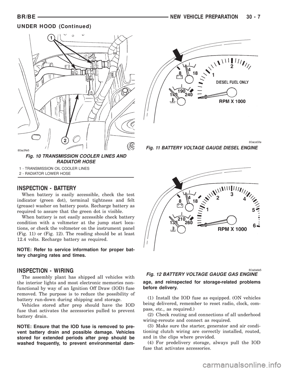
When battery is not easily accessible check battery
condition with a voltmeter at the jump start loca-
tions, or check the voltmeter on the instrument panel
(Fig. 11) or (Fig. 12). The reading should be at least
12.4 volts. Recharge battery as required.
NOTE: Refer to service information for proper bat-
tery charging rates and times.
INSPECTION - WIRING
The assembly plant has shipped all vehicles with
the interior lights and most electronic memories non-
functional by way of an Ignition Off Draw (IOD) fuse
removed. The purpose is to reduce the possibility of
battery run-down during shipping and storage.
Vehicles stored after prep should have the IOD
fuse that activates the accessories pulled to prevent
battery drain.
NOTE: Ensure that the IOD fuse is removed to pre-
vent battery drain and possible damage. Vehicles
stored for extended periods after prep should be
washed frequently, to prevent environmental dam-age, and reinspected for storage-related problems
before delivery.
(1) Install the IOD fuse as equipped. (ON vehicles
being delivered, remember to reset radio, clock, com-
pass, etc., as required.)
(2) Check routing and connections of all underhood
wiring-reroute and connect as required.
(3) Make sure the starter, generator and air condi-
tioning clutch wiring are correctly installed, routed,
and in the clips where provided.
(4) For predelivery storage, always pull the IOD
fuse that activates accessories.
Fig. 10 TRANSMISSION COOLER LINES AND
RADIATOR HOSE
1 - TRANSMISSION OIL COOLER LINES
2 - RADIATOR LOWER HOSE
Fig. 11 BATTERY VOLTAGE GAUGE DIESEL ENGINE
Fig. 12 BATTERY VOLTAGE GAUGE GAS ENGINE
BR/BENEW VEHICLE PREPARATION 30 - 7
UNDER HOOD (Continued)
Page 2833 of 2889
UNDER VEHICLE
INSPECTION - TIRE PRESSURES
(1) Using the tire placard or the Safety Certifica-
tion Label, check that the correct tires are mounted
on the vehicle.
(2) Install valve stem extensions as required.
(3) Using the tire placard or the Safety Certifica-
tion Label, check tire pressure (including spare) and
adjust as required to recommended pressure.
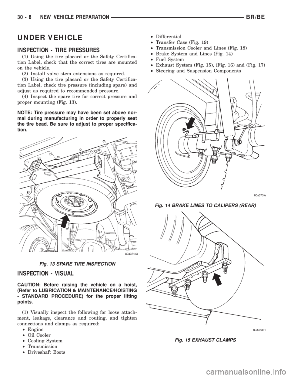
(4) Inspect the spare tire for correct pressure and
proper mounting (Fig. 13).
NOTE: Tire pressure may have been set above nor-
mal during manufacturing in order to properly seat
the tire bead. Be sure to adjust to proper specifica-
tion.
INSPECTION - VISUAL
CAUTION: Before raising the vehicle on a hoist,
(Refer to LUBRICATION & MAINTENANCE/HOISTING
- STANDARD PROCEDURE) for the proper lifting
points.
(1) Visually inspect the following for loose attach-
ment, leakage, clearance and routing, and tighten
connections and clamps as required:
²Engine
²Oil Cooler
²Cooling System
²Transmission
²Driveshaft Boots²Differential
²Transfer Case (Fig. 19)
²Transmission Cooler and Lines (Fig. 18)
²Brake System and Lines (Fig. 14)
²Fuel System
²Exhaust System (Fig. 15), (Fig. 16) and (Fig. 17)
²Steering and Suspension Components
Fig. 13 SPARE TIRE INSPECTION
Fig. 14 BRAKE LINES TO CALIPERS (REAR)
Fig. 15 EXHAUST CLAMPS
30 - 8 NEW VEHICLE PREPARATIONBR/BE