2001 DODGE RAM check oil
[x] Cancel search: check oilPage 2457 of 2889
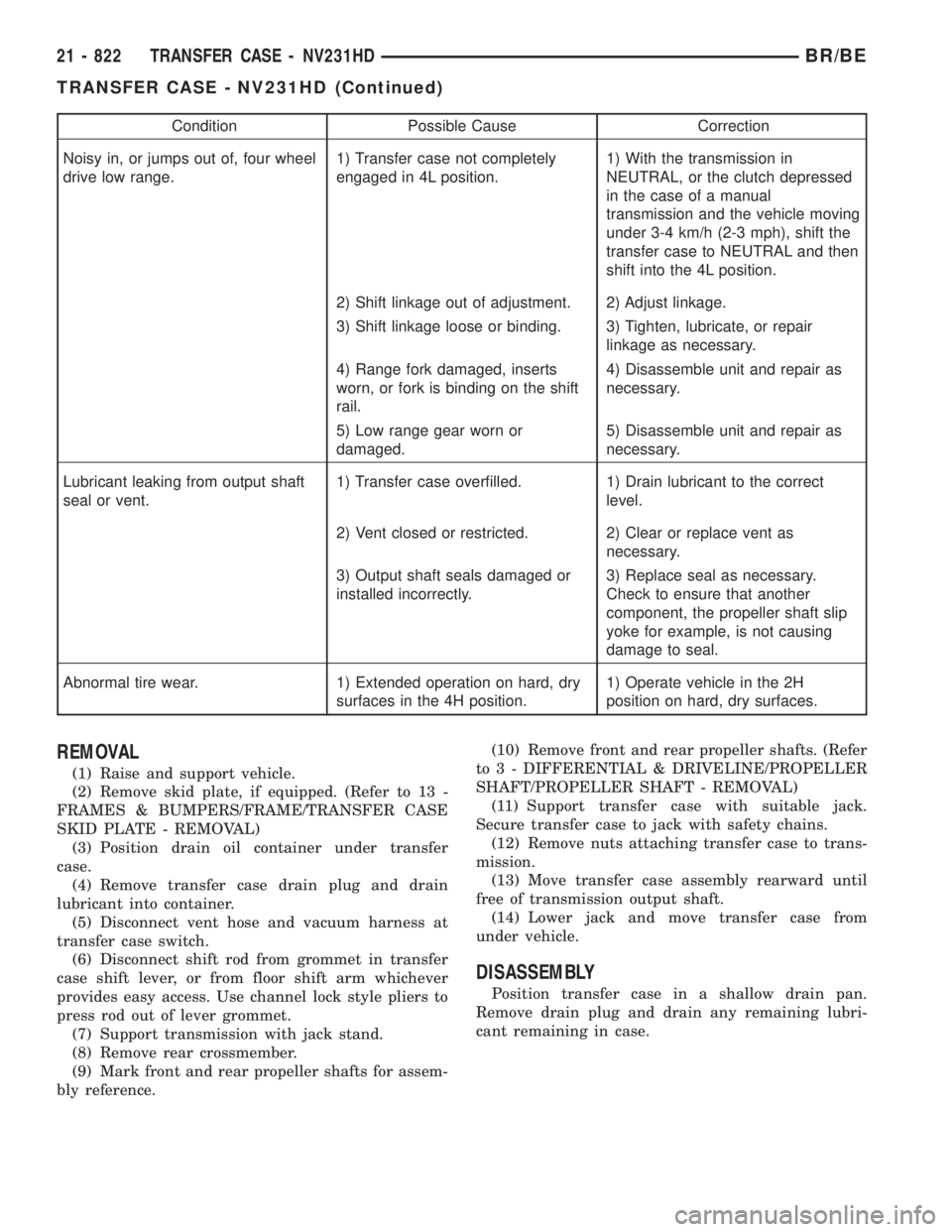
Condition Possible Cause Correction
Noisy in, or jumps out of, four wheel
drive low range.1) Transfer case not completely
engaged in 4L position.1) With the transmission in
NEUTRAL, or the clutch depressed
in the case of a manual
transmission and the vehicle moving
under 3-4 km/h (2-3 mph), shift the
transfer case to NEUTRAL and then
shift into the 4L position.
2) Shift linkage out of adjustment. 2) Adjust linkage.
3) Shift linkage loose or binding. 3) Tighten, lubricate, or repair
linkage as necessary.
4) Range fork damaged, inserts
worn, or fork is binding on the shift
rail.4) Disassemble unit and repair as
necessary.
5) Low range gear worn or
damaged.5) Disassemble unit and repair as
necessary.
Lubricant leaking from output shaft
seal or vent.1) Transfer case overfilled. 1) Drain lubricant to the correct
level.
2) Vent closed or restricted. 2) Clear or replace vent as
necessary.
3) Output shaft seals damaged or
installed incorrectly.3) Replace seal as necessary.
Check to ensure that another
component, the propeller shaft slip
yoke for example, is not causing
damage to seal.
Abnormal tire wear. 1) Extended operation on hard, dry
surfaces in the 4H position.1) Operate vehicle in the 2H
position on hard, dry surfaces.
REMOVAL
(1) Raise and support vehicle.
(2) Remove skid plate, if equipped. (Refer to 13 -
FRAMES & BUMPERS/FRAME/TRANSFER CASE
SKID PLATE - REMOVAL)
(3) Position drain oil container under transfer
case.
(4) Remove transfer case drain plug and drain
lubricant into container.
(5) Disconnect vent hose and vacuum harness at
transfer case switch.
(6) Disconnect shift rod from grommet in transfer
case shift lever, or from floor shift arm whichever
provides easy access. Use channel lock style pliers to
press rod out of lever grommet.
(7) Support transmission with jack stand.
(8) Remove rear crossmember.
(9) Mark front and rear propeller shafts for assem-
bly reference.(10) Remove front and rear propeller shafts. (Refer
to 3 - DIFFERENTIAL & DRIVELINE/PROPELLER
SHAFT/PROPELLER SHAFT - REMOVAL)
(11) Support transfer case with suitable jack.
Secure transfer case to jack with safety chains.
(12) Remove nuts attaching transfer case to trans-
mission.
(13) Move transfer case assembly rearward until
free of transmission output shaft.
(14) Lower jack and move transfer case from
under vehicle.
DISASSEMBLY
Position transfer case in a shallow drain pan.
Remove drain plug and drain any remaining lubri-
cant remaining in case.
21 - 822 TRANSFER CASE - NV231HDBR/BE
TRANSFER CASE - NV231HD (Continued)
Page 2467 of 2889
INSPECTION
MAINSHAFT/SPROCKET/HUB
Inspect the splines on the hub and shaft and the
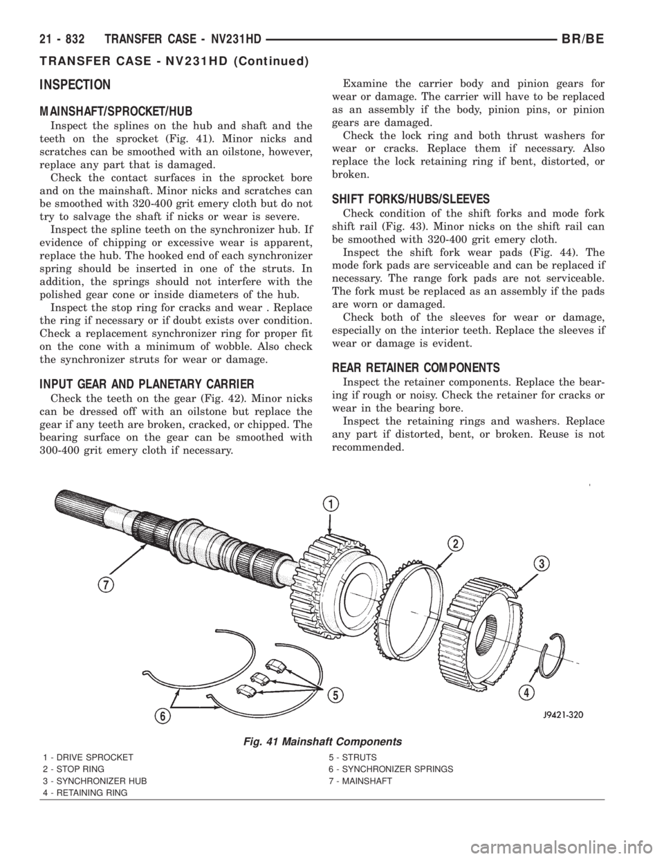
teeth on the sprocket (Fig. 41). Minor nicks and
scratches can be smoothed with an oilstone, however,
replace any part that is damaged.
Check the contact surfaces in the sprocket bore
and on the mainshaft. Minor nicks and scratches can
be smoothed with 320-400 grit emery cloth but do not
try to salvage the shaft if nicks or wear is severe.
Inspect the spline teeth on the synchronizer hub. If
evidence of chipping or excessive wear is apparent,
replace the hub. The hooked end of each synchronizer
spring should be inserted in one of the struts. In
addition, the springs should not interfere with the
polished gear cone or inside diameters of the hub.
Inspect the stop ring for cracks and wear . Replace
the ring if necessary or if doubt exists over condition.
Check a replacement synchronizer ring for proper fit
on the cone with a minimum of wobble. Also check
the synchronizer struts for wear or damage.
INPUT GEAR AND PLANETARY CARRIER
Check the teeth on the gear (Fig. 42). Minor nicks
can be dressed off with an oilstone but replace the
gear if any teeth are broken, cracked, or chipped. The
bearing surface on the gear can be smoothed with
300-400 grit emery cloth if necessary.Examine the carrier body and pinion gears for
wear or damage. The carrier will have to be replaced
as an assembly if the body, pinion pins, or pinion
gears are damaged.
Check the lock ring and both thrust washers for
wear or cracks. Replace them if necessary. Also
replace the lock retaining ring if bent, distorted, or
broken.
SHIFT FORKS/HUBS/SLEEVES
Check condition of the shift forks and mode fork
shift rail (Fig. 43). Minor nicks on the shift rail can
be smoothed with 320-400 grit emery cloth.
Inspect the shift fork wear pads (Fig. 44). The
mode fork pads are serviceable and can be replaced if
necessary. The range fork pads are not serviceable.
The fork must be replaced as an assembly if the pads
are worn or damaged.
Check both of the sleeves for wear or damage,
especially on the interior teeth. Replace the sleeves if
wear or damage is evident.
REAR RETAINER COMPONENTS
Inspect the retainer components. Replace the bear-
ing if rough or noisy. Check the retainer for cracks or
wear in the bearing bore.
Inspect the retaining rings and washers. Replace
any part if distorted, bent, or broken. Reuse is not
recommended.
Fig. 41 Mainshaft Components
1 - DRIVE SPROCKET 5 - STRUTS
2 - STOP RING 6 - SYNCHRONIZER SPRINGS
3 - SYNCHRONIZER HUB 7 - MAINSHAFT
4 - RETAINING RING
21 - 832 TRANSFER CASE - NV231HDBR/BE
TRANSFER CASE - NV231HD (Continued)
Page 2469 of 2889
LOW RANGE ANNULUS GEAR
Inspect annulus gear condition carefully. The gear
is only serviced as part of the front case. If the gear
is damaged, it will be necessary to replace the gear
and front case as an assembly. Do not attempt to
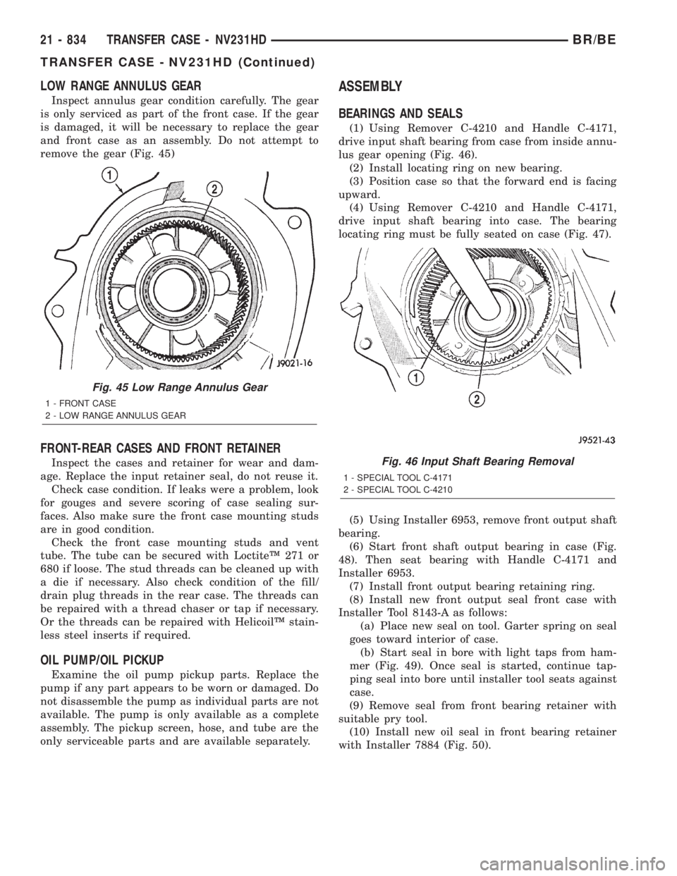
remove the gear (Fig. 45)
FRONT-REAR CASES AND FRONT RETAINER
Inspect the cases and retainer for wear and dam-
age. Replace the input retainer seal, do not reuse it.
Check case condition. If leaks were a problem, look
for gouges and severe scoring of case sealing sur-
faces. Also make sure the front case mounting studs
are in good condition.
Check the front case mounting studs and vent
tube. The tube can be secured with LoctiteŸ 271 or
680 if loose. The stud threads can be cleaned up with
a die if necessary. Also check condition of the fill/
drain plug threads in the rear case. The threads can
be repaired with a thread chaser or tap if necessary.
Or the threads can be repaired with HelicoilŸ stain-
less steel inserts if required.
OIL PUMP/OIL PICKUP
Examine the oil pump pickup parts. Replace the
pump if any part appears to be worn or damaged. Do
not disassemble the pump as individual parts are not
available. The pump is only available as a complete
assembly. The pickup screen, hose, and tube are the
only serviceable parts and are available separately.
ASSEMBLY
BEARINGS AND SEALS
(1) Using Remover C-4210 and Handle C-4171,
drive input shaft bearing from case from inside annu-
lus gear opening (Fig. 46).
(2) Install locating ring on new bearing.
(3) Position case so that the forward end is facing
upward.
(4) Using Remover C-4210 and Handle C-4171,
drive input shaft bearing into case. The bearing
locating ring must be fully seated on case (Fig. 47).
(5) Using Installer 6953, remove front output shaft
bearing.
(6) Start front shaft output bearing in case (Fig.
48). Then seat bearing with Handle C-4171 and
Installer 6953.
(7) Install front output bearing retaining ring.
(8) Install new front output seal front case with
Installer Tool 8143-A as follows:
(a) Place new seal on tool. Garter spring on seal
goes toward interior of case.
(b) Start seal in bore with light taps from ham-
mer (Fig. 49). Once seal is started, continue tap-
ping seal into bore until installer tool seats against
case.
(9) Remove seal from front bearing retainer with
suitable pry tool.
(10) Install new oil seal in front bearing retainer
with Installer 7884 (Fig. 50).
Fig. 45 Low Range Annulus Gear
1 - FRONT CASE
2 - LOW RANGE ANNULUS GEAR
Fig. 46 Input Shaft Bearing Removal
1 - SPECIAL TOOL C-4171
2 - SPECIAL TOOL C-4210
21 - 834 TRANSFER CASE - NV231HDBR/BE
TRANSFER CASE - NV231HD (Continued)
Page 2480 of 2889
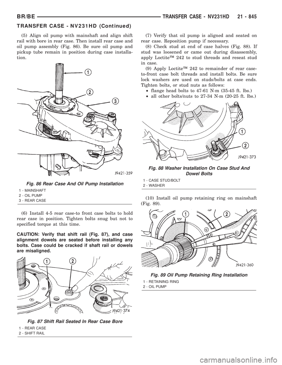
(5) Align oil pump with mainshaft and align shift
rail with bore in rear case. Then install rear case and
oil pump assembly (Fig. 86). Be sure oil pump and
pickup tube remain in position during case installa-
tion.
(6) Install 4-5 rear case-to front case bolts to hold
rear case in position. Tighten bolts snug but not to
specified torque at this time.
CAUTION: Verify that shift rail (Fig. 87), and case
alignment dowels are seated before installing any
bolts. Case could be cracked if shaft rail or dowels
are misaligned.(7) Verify that oil pump is aligned and seated on
rear case. Reposition pump if necessary.
(8) Check stud at end of case halves (Fig. 88). If
stud was loosened or came out during disassembly,
apply LoctiteŸ 242 to stud threads and reseat stud
in case.
(9) Apply LoctiteŸ 242 to remainder of rear case-
to-front case bolt threads and install bolts. Be sure
lock washers are used on studs/bolts at case ends.
Tighten bolts, or stud nuts as follows:
²flange head bolts to 47-61 N´m (35-45 ft. lbs.)
²all other bolts/nuts to 27-34 N´m (20-25 ft. lbs.)
(10) Install oil pump retaining ring on mainshaft
(Fig. 89).
Fig. 86 Rear Case And Oil Pump Installation
1 - MAINSHAFT
2 - OIL PUMP
3 - REAR CASE
Fig. 87 Shift Rail Seated In Rear Case Bore
1 - REAR CASE
2 - SHIFT RAIL
Fig. 88 Washer Installation On Case Stud And
Dowel Bolts
1 - CASE STUD/BOLT
2 - WASHER
Fig. 89 Oil Pump Retaining Ring Installation
1 - RETAINING RING
2 - OIL PUMP
BR/BETRANSFER CASE - NV231HD 21 - 845
TRANSFER CASE - NV231HD (Continued)
Page 2502 of 2889
INSPECTION
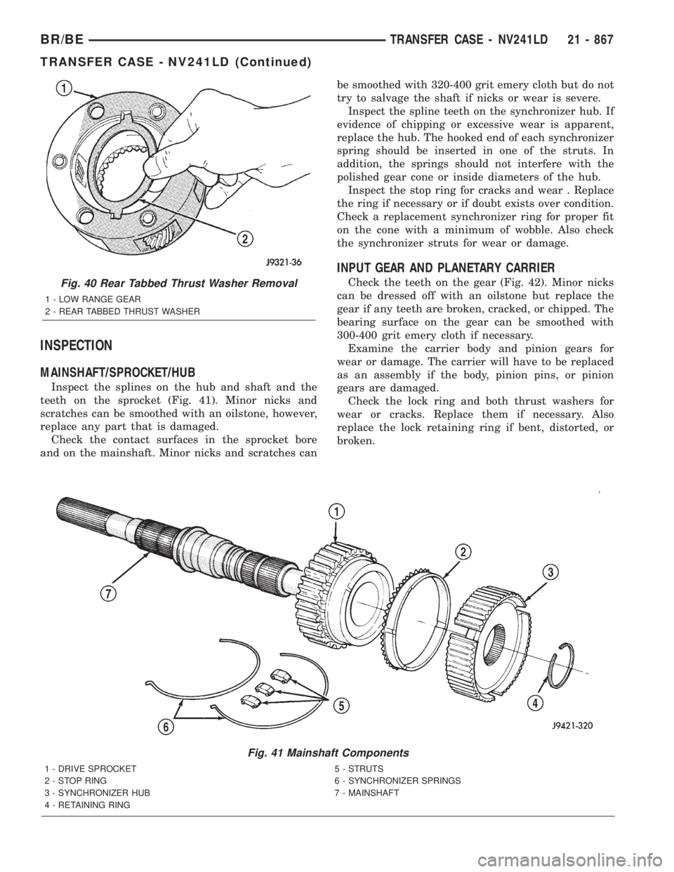
MAINSHAFT/SPROCKET/HUB
Inspect the splines on the hub and shaft and the
teeth on the sprocket (Fig. 41). Minor nicks and
scratches can be smoothed with an oilstone, however,
replace any part that is damaged.
Check the contact surfaces in the sprocket bore
and on the mainshaft. Minor nicks and scratches canbe smoothed with 320-400 grit emery cloth but do not
try to salvage the shaft if nicks or wear is severe.
Inspect the spline teeth on the synchronizer hub. If
evidence of chipping or excessive wear is apparent,
replace the hub. The hooked end of each synchronizer
spring should be inserted in one of the struts. In
addition, the springs should not interfere with the
polished gear cone or inside diameters of the hub.
Inspect the stop ring for cracks and wear . Replace
the ring if necessary or if doubt exists over condition.
Check a replacement synchronizer ring for proper fit
on the cone with a minimum of wobble. Also check
the synchronizer struts for wear or damage.
INPUT GEAR AND PLANETARY CARRIER
Check the teeth on the gear (Fig. 42). Minor nicks
can be dressed off with an oilstone but replace the
gear if any teeth are broken, cracked, or chipped. The
bearing surface on the gear can be smoothed with
300-400 grit emery cloth if necessary.
Examine the carrier body and pinion gears for
wear or damage. The carrier will have to be replaced
as an assembly if the body, pinion pins, or pinion
gears are damaged.
Check the lock ring and both thrust washers for
wear or cracks. Replace them if necessary. Also
replace the lock retaining ring if bent, distorted, or
broken.
Fig. 41 Mainshaft Components
1 - DRIVE SPROCKET 5 - STRUTS
2 - STOP RING 6 - SYNCHRONIZER SPRINGS
3 - SYNCHRONIZER HUB 7 - MAINSHAFT
4 - RETAINING RING
Fig. 40 Rear Tabbed Thrust Washer Removal
1 - LOW RANGE GEAR
2 - REAR TABBED THRUST WASHER
BR/BETRANSFER CASE - NV241LD 21 - 867
TRANSFER CASE - NV241LD (Continued)
Page 2504 of 2889
REAR RETAINER COMPONENTS
Inspect the retainer components. Replace the bear-
ing if rough or noisy. Check the retainer for cracks or
wear in the bearing bore.
Inspect the retaining rings and washers. Replace
any part if distorted, bent, or broken. Reuse is not
recommended.
Inspect rear extension bushing. Replace if worn or
scored.
DRIVE CHAIN
Examine the drive chain and shaft bearings.
replace the chain if stretched, distorted, or if any of
the links bind. Replace the bearings if rough, or
noisy.
LOW RANGE ANNULUS GEAR
Inspect annulus gear condition carefully. The gear
is only serviced as part of the front case. If the gear
is damaged, it will be necessary to replace the gear
and front case as an assembly. Do not attempt to
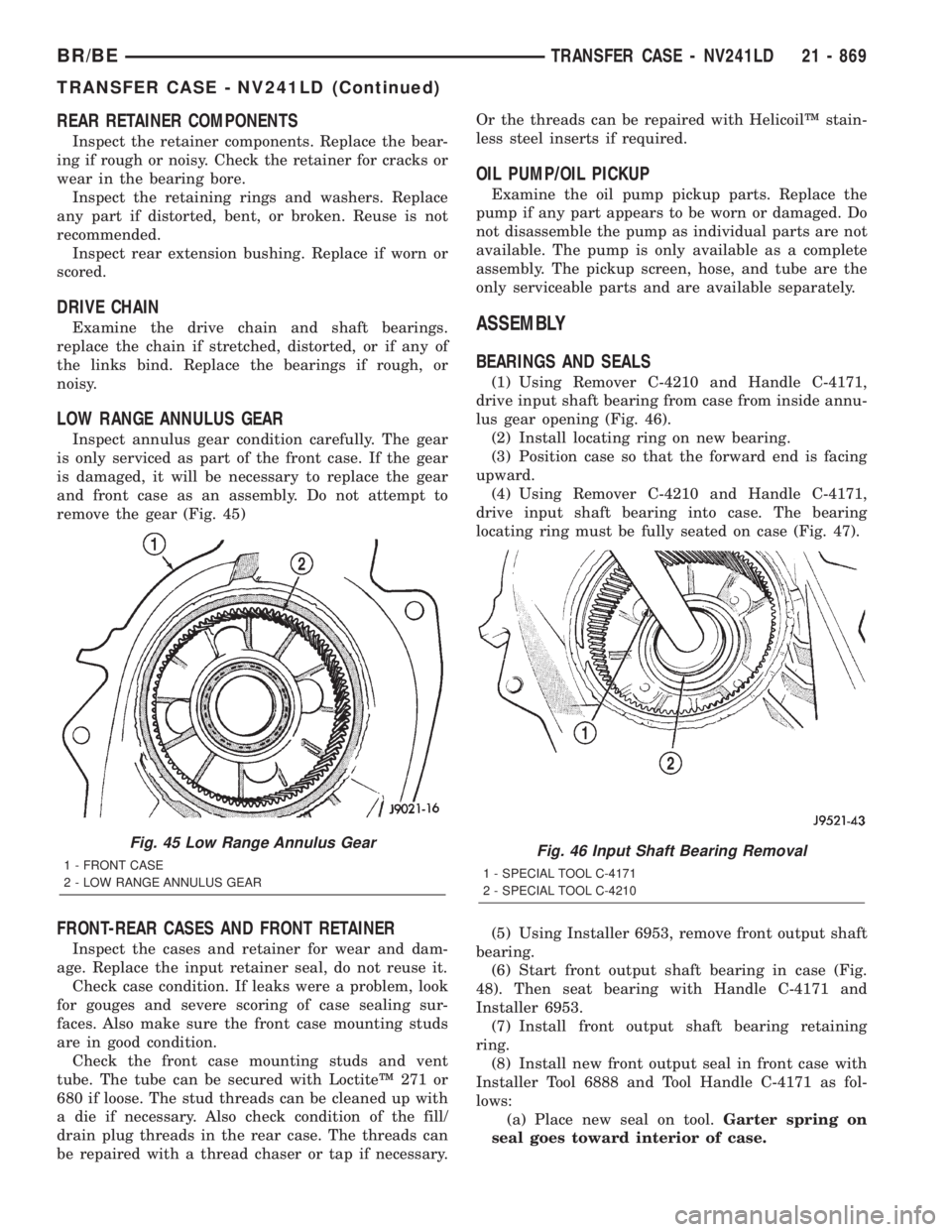
remove the gear (Fig. 45)
FRONT-REAR CASES AND FRONT RETAINER
Inspect the cases and retainer for wear and dam-
age. Replace the input retainer seal, do not reuse it.
Check case condition. If leaks were a problem, look
for gouges and severe scoring of case sealing sur-
faces. Also make sure the front case mounting studs
are in good condition.
Check the front case mounting studs and vent
tube. The tube can be secured with LoctiteŸ 271 or
680 if loose. The stud threads can be cleaned up with
a die if necessary. Also check condition of the fill/
drain plug threads in the rear case. The threads can
be repaired with a thread chaser or tap if necessary.Or the threads can be repaired with HelicoilŸ stain-
less steel inserts if required.
OIL PUMP/OIL PICKUP
Examine the oil pump pickup parts. Replace the
pump if any part appears to be worn or damaged. Do
not disassemble the pump as individual parts are not
available. The pump is only available as a complete
assembly. The pickup screen, hose, and tube are the
only serviceable parts and are available separately.
ASSEMBLY
BEARINGS AND SEALS
(1) Using Remover C-4210 and Handle C-4171,
drive input shaft bearing from case from inside annu-
lus gear opening (Fig. 46).
(2) Install locating ring on new bearing.
(3) Position case so that the forward end is facing
upward.
(4) Using Remover C-4210 and Handle C-4171,
drive input shaft bearing into case. The bearing
locating ring must be fully seated on case (Fig. 47).
(5) Using Installer 6953, remove front output shaft
bearing.
(6) Start front output shaft bearing in case (Fig.
48). Then seat bearing with Handle C-4171 and
Installer 6953.
(7) Install front output shaft bearing retaining
ring.
(8) Install new front output seal in front case with
Installer Tool 6888 and Tool Handle C-4171 as fol-
lows:
(a) Place new seal on tool.Garter spring on
seal goes toward interior of case.
Fig. 45 Low Range Annulus Gear
1 - FRONT CASE
2 - LOW RANGE ANNULUS GEARFig. 46 Input Shaft Bearing Removal
1 - SPECIAL TOOL C-4171
2 - SPECIAL TOOL C-4210
BR/BETRANSFER CASE - NV241LD 21 - 869
TRANSFER CASE - NV241LD (Continued)
Page 2515 of 2889
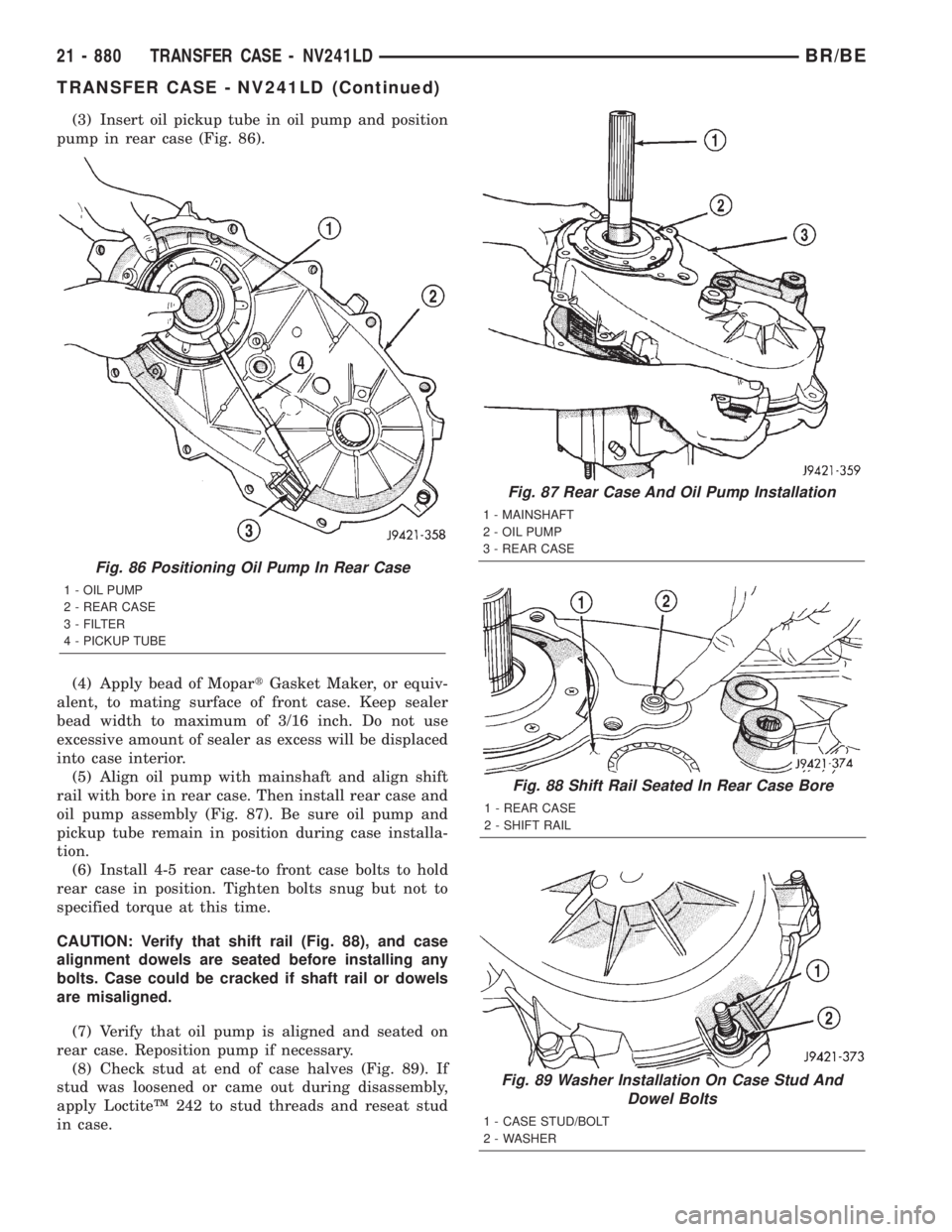
(3) Insert oil pickup tube in oil pump and position
pump in rear case (Fig. 86).
(4) Apply bead of MopartGasket Maker, or equiv-
alent, to mating surface of front case. Keep sealer
bead width to maximum of 3/16 inch. Do not use
excessive amount of sealer as excess will be displaced
into case interior.
(5) Align oil pump with mainshaft and align shift
rail with bore in rear case. Then install rear case and
oil pump assembly (Fig. 87). Be sure oil pump and
pickup tube remain in position during case installa-
tion.
(6) Install 4-5 rear case-to front case bolts to hold
rear case in position. Tighten bolts snug but not to
specified torque at this time.
CAUTION: Verify that shift rail (Fig. 88), and case
alignment dowels are seated before installing any
bolts. Case could be cracked if shaft rail or dowels
are misaligned.
(7) Verify that oil pump is aligned and seated on
rear case. Reposition pump if necessary.
(8) Check stud at end of case halves (Fig. 89). If
stud was loosened or came out during disassembly,
apply LoctiteŸ 242 to stud threads and reseat stud
in case.
Fig. 87 Rear Case And Oil Pump Installation
1 - MAINSHAFT
2 - OIL PUMP
3 - REAR CASE
Fig. 88 Shift Rail Seated In Rear Case Bore
1 - REAR CASE
2 - SHIFT RAIL
Fig. 89 Washer Installation On Case Stud And
Dowel Bolts
1 - CASE STUD/BOLT
2 - WASHER
Fig. 86 Positioning Oil Pump In Rear Case
1 - OIL PUMP
2 - REAR CASE
3 - FILTER
4 - PICKUP TUBE
21 - 880 TRANSFER CASE - NV241LDBR/BE
TRANSFER CASE - NV241LD (Continued)
Page 2538 of 2889
Check a replacement synchronizer ring for proper fit
on the cone with a minimum of wobble. Also check
the synchronizer struts for wear or damage.
Inspect all gear teeth and splines for wear or dam-
age. Also check splines for burrs, or nicks. Remove
minor nicks and scratches with an oil stone. Replace
any part with damaged splines.
It is recommended that all retaining rings be replaced
during overhaul. Most of the retaining rings can be dis-
torted during removal and should not be reused.
Inspect the two case halves, for cracks, porosity,
damaged mating surfaces, stripped bolt threads, or
distortion. Replace either case half if necessary. How-
ever, stripped threads can be repaired with Heli-
CoilŸ stainless steel thread inserts. The case vent
tube can be resecured with LoctiteŸ 680 if necessary.
Inspect the annulus gear. Be sure the gear teeth
are in good condition. Replace the front case and
annulus as an assembly if the gear is damaged.
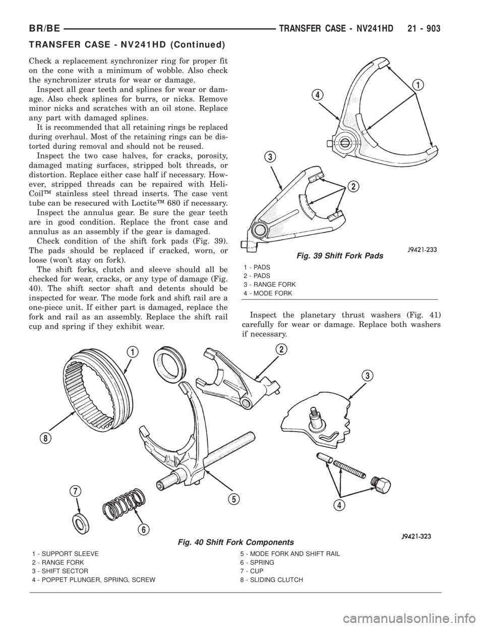
Check condition of the shift fork pads (Fig. 39).
The pads should be replaced if cracked, worn, or
loose (won't stay on fork).
The shift forks, clutch and sleeve should all be
checked for wear, cracks, or any type of damage (Fig.
40). The shift sector shaft and detents should be
inspected for wear. The mode fork and shift rail are a
one-piece unit. If either part is damaged, replace the
fork and rail as an assembly. Replace the shift rail
cup and spring if they exhibit wear.Inspect the planetary thrust washers (Fig. 41)
carefully for wear or damage. Replace both washers
if necessary.
Fig. 39 Shift Fork Pads
1-PADS
2-PADS
3 - RANGE FORK
4 - MODE FORK
Fig. 40 Shift Fork Components
1 - SUPPORT SLEEVE 5 - MODE FORK AND SHIFT RAIL
2 - RANGE FORK 6 - SPRING
3 - SHIFT SECTOR 7 - CUP
4 - POPPET PLUNGER, SPRING, SCREW 8 - SLIDING CLUTCH
BR/BETRANSFER CASE - NV241HD 21 - 903
TRANSFER CASE - NV241HD (Continued)