Page 1747 of 2889
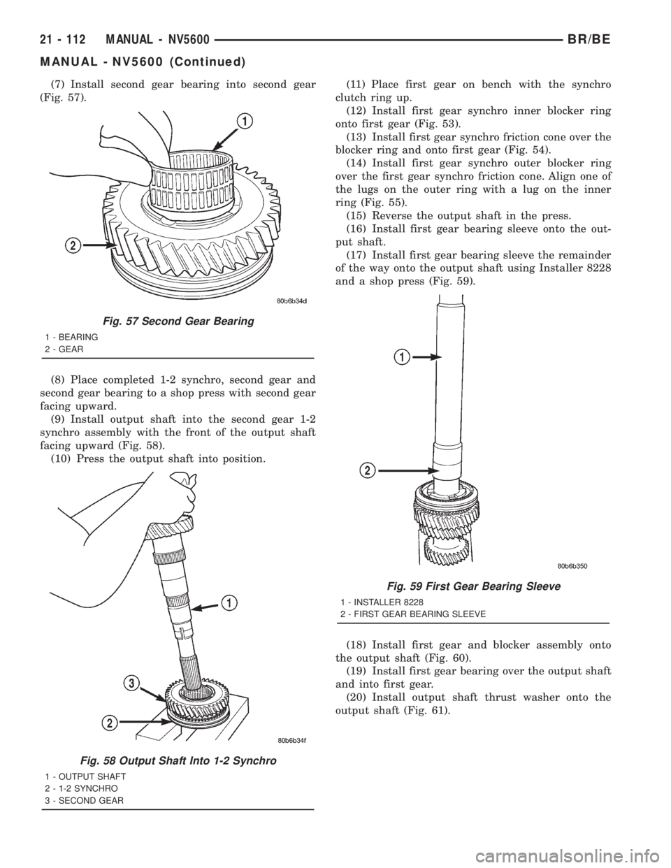
(7) Install second gear bearing into second gear
(Fig. 57).
(8) Place completed 1-2 synchro, second gear and
second gear bearing to a shop press with second gear
facing upward.
(9) Install output shaft into the second gear 1-2
synchro assembly with the front of the output shaft
facing upward (Fig. 58).
(10) Press the output shaft into position.(11) Place first gear on bench with the synchro
clutch ring up.
(12) Install first gear synchro inner blocker ring
onto first gear (Fig. 53).
(13) Install first gear synchro friction cone over the
blocker ring and onto first gear (Fig. 54).
(14) Install first gear synchro outer blocker ring
over the first gear synchro friction cone. Align one of
the lugs on the outer ring with a lug on the inner
ring (Fig. 55).
(15) Reverse the output shaft in the press.
(16) Install first gear bearing sleeve onto the out-
put shaft.
(17) Install first gear bearing sleeve the remainder
of the way onto the output shaft using Installer 8228
and a shop press (Fig. 59).
(18) Install first gear and blocker assembly onto
the output shaft (Fig. 60).
(19) Install first gear bearing over the output shaft
and into first gear.
(20) Install output shaft thrust washer onto the
output shaft (Fig. 61).
Fig. 57 Second Gear Bearing
1 - BEARING
2 - GEAR
Fig. 58 Output Shaft Into 1-2 Synchro
1 - OUTPUT SHAFT
2 - 1-2 SYNCHRO
3 - SECOND GEAR
Fig. 59 First Gear Bearing Sleeve
1 - INSTALLER 8228
2 - FIRST GEAR BEARING SLEEVE
21 - 112 MANUAL - NV5600BR/BE
MANUAL - NV5600 (Continued)
Page 1748 of 2889
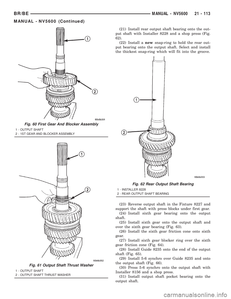
(21) Install rear output shaft bearing onto the out-
put shaft with Installer 8228 and a shop press (Fig.
62).
(22) Install anewsnap-ring to hold the rear out-
put bearing onto the output shaft. Select and install
the thickest snap-ring which will fit into the groove.
(23) Reverse output shaft in the Fixture 8227 and
support the shaft with press blocks under first gear.
(24) Install sixth gear bearing onto the output
shaft.
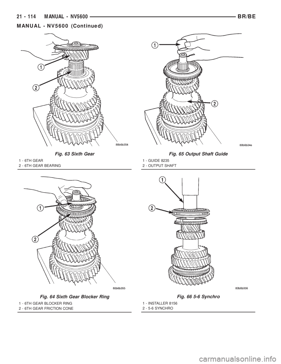
(25) Install sixth gear onto the output shaft and
over the sixth gear bearing (Fig. 63).
(26) Install the sixth gear friction cone onto sixth
gear.
(27) Install sixth gear blocker ring over the sixth
gear friction cone (Fig. 64).
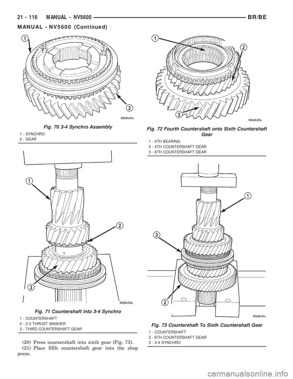
(28) Install Guide 8235 onto the end of the output
shaft (Fig. 65).
(29) Install 5-6 synchro over Guide 8235 and onto
the output shaft (Fig. 66).
(30) Press 5-6 synchro onto the output shaft with
Installer 8156 and a shop press.
(31) Install output shaft pocket bearing onto the
output shaft.
Fig. 60 First Gear And Blocker Assembly
1 - OUTPUT SHAFT
2 - 1ST GEAR AND BLOCKER ASSEMBLY
Fig. 61 Output Shaft Thrust Washer
1 - OUTPUT SHAFT
2 - OUTPUT SHAFT THRUST WASHER
Fig. 62 Rear Output Shaft Bearing
1 - INSTALLER 8228
2 - REAR OUTPUT SHAFT BEARING
BR/BEMANUAL - NV5600 21 - 113
MANUAL - NV5600 (Continued)
Page 1749 of 2889
Fig. 63 Sixth Gear
1 - 6TH GEAR
2 - 6TH GEAR BEARING
Fig. 64 Sixth Gear Blocker Ring
1 - 6TH GEAR BLOCKER RING
2 - 6TH GEAR FRICTION CONE
Fig. 65 Output Shaft Guide
1 - GUIDE 8235
2 - OUTPUT SHAFT
Fig. 66 5-6 Synchro
1 - INSTALLER 8156
2 - 5-6 SYNCHRO
21 - 114 MANUAL - NV5600BR/BE
MANUAL - NV5600 (Continued)
Page 1750 of 2889
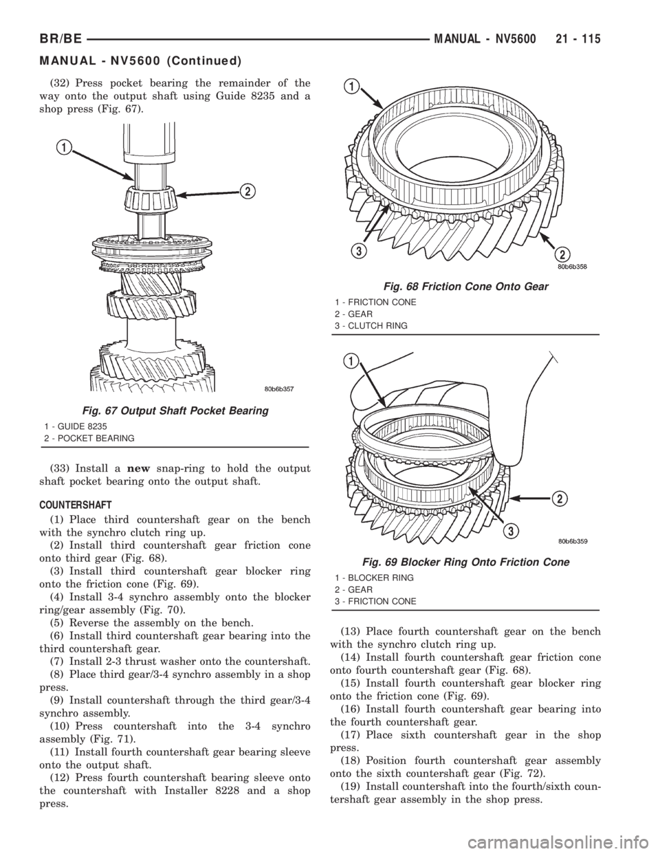
(32) Press pocket bearing the remainder of the
way onto the output shaft using Guide 8235 and a
shop press (Fig. 67).
(33) Install anewsnap-ring to hold the output
shaft pocket bearing onto the output shaft.
COUNTERSHAFT
(1) Place third countershaft gear on the bench
with the synchro clutch ring up.
(2) Install third countershaft gear friction cone
onto third gear (Fig. 68).
(3) Install third countershaft gear blocker ring
onto the friction cone (Fig. 69).
(4) Install 3-4 synchro assembly onto the blocker
ring/gear assembly (Fig. 70).
(5) Reverse the assembly on the bench.
(6) Install third countershaft gear bearing into the
third countershaft gear.
(7) Install 2-3 thrust washer onto the countershaft.
(8) Place third gear/3-4 synchro assembly in a shop
press.
(9) Install countershaft through the third gear/3-4
synchro assembly.
(10) Press countershaft into the 3-4 synchro
assembly (Fig. 71).
(11) Install fourth countershaft gear bearing sleeve
onto the output shaft.
(12) Press fourth countershaft bearing sleeve onto
the countershaft with Installer 8228 and a shop
press.(13) Place fourth countershaft gear on the bench
with the synchro clutch ring up.
(14) Install fourth countershaft gear friction cone
onto fourth countershaft gear (Fig. 68).
(15) Install fourth countershaft gear blocker ring
onto the friction cone (Fig. 69).
(16) Install fourth countershaft gear bearing into
the fourth countershaft gear.
(17) Place sixth countershaft gear in the shop
press.
(18) Position fourth countershaft gear assembly
onto the sixth countershaft gear (Fig. 72).
(19) Install countershaft into the fourth/sixth coun-
tershaft gear assembly in the shop press.
Fig. 67 Output Shaft Pocket Bearing
1 - GUIDE 8235
2 - POCKET BEARING
Fig. 68 Friction Cone Onto Gear
1 - FRICTION CONE
2 - GEAR
3 - CLUTCH RING
Fig. 69 Blocker Ring Onto Friction Cone
1 - BLOCKER RING
2 - GEAR
3 - FRICTION CONE
BR/BEMANUAL - NV5600 21 - 115
MANUAL - NV5600 (Continued)
Page 1751 of 2889
(20) Press countershaft into sixth gear (Fig. 73).
(21) Place fifth countershaft gear into the shop
press.
Fig. 70 3-4 Synchro Assembly
1 - SYNCHRO
2 - GEAR
Fig. 71 Countershaft into 3-4 Synchro
1 - COUNTERSHAFT
2 - 2-3 THRUST WASHER
3 - THIRD COUNTERSHAFT GEAR
Fig. 72 Fourth Countershaft onto Sixth Countershaft
Gear
1 - 4TH BEARING
2 - 4TH COUNTERSHAFT GEAR
3 - 6TH COUNTERSHAFT GEAR
Fig. 73 Countershaft To Sixth Countershaft Gear
1 - COUNTERSHAFT
2 - 6TH COUNTERSHAFT GEAR
3 - 3-4 SYNCHRO
21 - 116 MANUAL - NV5600BR/BE
MANUAL - NV5600 (Continued)
Page 1752 of 2889
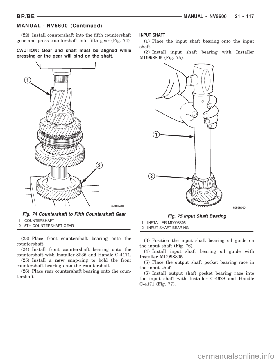
(22) Install countershaft into the fifth countershaft
gear and press countershaft into fifth gear (Fig. 74).
CAUTION: Gear and shaft must be aligned while
pressing or the gear will bind on the shaft.
(23) Place front countershaft bearing onto the
countershaft.
(24) Install front countershaft bearing onto the
countershaft with Installer 8236 and Handle C-4171.
(25) Install anewsnap-ring to hold the front
countershaft bearing onto the countershaft.
(26) Place rear countershaft bearing onto the coun-
tershaft.INPUT SHAFT
(1) Place the input shaft bearing onto the input
shaft.
(2) Install input shaft bearing with Installer
MD998805 (Fig. 75).
(3) Position the input shaft bearing oil guide on
the input shaft (Fig. 76).
(4) Install input shaft bearing oil guide with
Installer MD998805.
(5) Place the output shaft pocket bearing race in
the input shaft.
(6) Install output shaft pocket bearing race into
the input shaft with Installer C-4628 and Handle
C-4171 (Fig. 77).
Fig. 74 Countershaft to Fifth Countershaft Gear
1 - COUNTERSHAFT
2 - 5TH COUNTERSHAFT GEARFig. 75 Input Shaft Bearing
1 - INSTALLER MD998805
2 - INPUT SHAFT BEARING
BR/BEMANUAL - NV5600 21 - 117
MANUAL - NV5600 (Continued)
Page 1753 of 2889
CLUTCH HOUSING
(1) Install input shaft bearing race so that the
bearing race protrudes 0.3 in. above the front surface
of the clutch housing. Install bearing race with
Remover/Installer 8237 and Handle C-4171.
(2) Install countershaft front bearing race into the
clutch housing so that the bearing race protrudes 0.4
in. above the front surface of the clutch housing.
Install bearing race with Remover 6061-1 and Han-
dle C-4171.
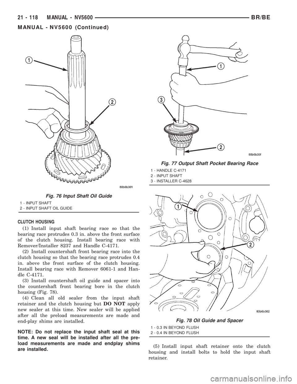
(3) Install countershaft oil guide and spacer into
the countershaft front bearing bore in the clutch
housing (Fig. 78).
(4) Clean all old sealer from the input shaft
retainer and the clutch housing butDO NOTapply
new sealer at this time. New sealer will be applied
after all the preload measurements are made and
end-play shims are installed.
NOTE: Do not replace the input shaft seal at this
time. A new seal will be installed after all the pre-
load measurements are made and endplay shims
are installed.(5) Install input shaft retainer onto the clutch
housing and install bolts to hold the input shaft
retainer.
Fig. 76 Input Shaft Oil Guide
1 - INPUT SHAFT
2 - INPUT SHAFT OIL GUIDE
Fig. 77 Output Shaft Pocket Bearing Race
1 - HANDLE C-4171
2 - INPUT SHAFT
3 - INSTALLER C-4628
Fig. 78 Oil Guide and Spacer
1 - 0.3 IN BEYOND FLUSH
2 - 0.4 IN BEYOND FLUSH
21 - 118 MANUAL - NV5600BR/BE
MANUAL - NV5600 (Continued)
Page 1754 of 2889
GEARTRAIN
(1) Install input shaft into Support Stand 8246.
(2) Install fifth gear friction cone onto the input
shaft.
(3) Install fifth gear blocker ring onto the fifth
gear friction cone.
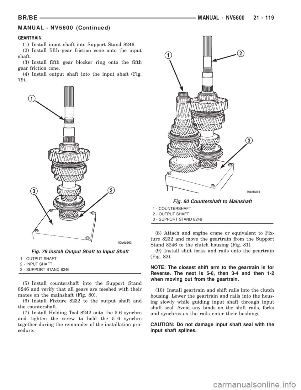
(4) Install output shaft into the input shaft (Fig.
79).
(5) Install countershaft into the Support Stand
8246 and verify that all gears are meshed with their
mates on the mainshaft (Fig. 80).
(6) Install Fixture 8232 to the output shaft and
the countershaft.
(7) Install Holding Tool 8242 onto the 5-6 synchro
and tighten the screw to hold the 5±6 synchro
together during the remainder of the installation pro-
cedure.(8) Attach and engine crane or equivalent to Fix-
ture 8232 and move the geartrain from the Support
Stand 8246 to the clutch housing (Fig. 81).
(9) Install shift forks and rails onto the geartrain
(Fig. 82).
NOTE: The closest shift arm to the geartrain is for
Reverse. The next is 5-6, then 3-4 and then 1-2
when moving out from the geartrain.
(10) Install geartrain and shift rails into the clutch
housing. Lower the geartrain and rails into the hous-
ing slowly while guiding input shaft through input
shaft seal. Avoid any binds on the shift rails, forks
and synchros as the rails enter their bushings.
CAUTION: Do not damage input shaft seal with the
input shaft splines.
Fig. 79 Install Output Shaft to Input Shaft
1 - OUTPUT SHAFT
2 - INPUT SHAFT
3 - SUPPORT STAND 8246
Fig. 80 Countershaft to Mainshaft
1 - COUNTERSHAFT
2 - OUTPUT SHAFT
3 - SUPPORT STAND 8246
BR/BEMANUAL - NV5600 21 - 119
MANUAL - NV5600 (Continued)