2001 DODGE RAM Valve body
[x] Cancel search: Valve bodyPage 12 of 2889
tification Number. The check digit is used by the
manufacturer and government agencies to verify the
authenticity of the vehicle and official documenta-
tion. The formula to use the check digit is not
released to the general public.
POSITION INTERPRETATION CODE = DESCRIPTION
1 Country of Origin 1 = United States
3 = Mexico
2 Make B = Dodge
3 Vehicle Type 6 = Incomplete
7 = Truck
4 Gross Vehicle Weight Rating H = 6001-7000
J = 7001-8000
K = 8001-9000
L = 9001-10,000
M = 10,001-14,000
5 Vehicle Line C = Ram Cab Chassis/Ram Pick Up (4x2)
F = Ram Cab Chassis/Ram Pick Up (4x4)
6 Series 1 = 1500
2 = 2500
3 = 3500
7 Body Style 2 = Club Cab
3 = Quad Cab
6 = Conventional Cab/Cab Chassis
8 Engine 6 = 5.9L 6 cyl. 24 Valve Diesel
7=5.9 6cyl. 24 Valve Turbo Diesel H/O
W = 8.0L 10 cyl. MPI
X = 3.9L 6 cyl. MPI
Y = 5.2L 8 cyl. MPI
Z = 5.9L 8 cyl. MPI-LDC
5 = 5.9L 8cyl. MPI-HDC
9 Check Digit 0 through 9 or X
10 Model Year 1=2001
11 Plant Location J = St. Louis North
S = Dodge City
M = Lago Alberto Assembly
12 thru 17 Vehicle Build Sequence
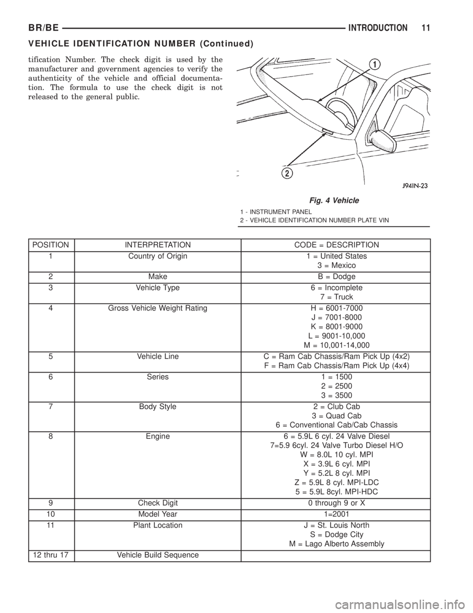
Fig. 4 Vehicle
1 - INSTRUMENT PANEL
2 - VEHICLE IDENTIFICATION NUMBER PLATE VIN
BR/BEINTRODUCTION 11
VEHICLE IDENTIFICATION NUMBER (Continued)
Page 300 of 2889
(6) Position adjuster lever return spring on pivot.
(7) Install adjuster lever.
(8) Attach adjuster cable to adjuster lever. Be sure
cable is properly routed.
(9) Adjust brake shoes to drum with brake gauge.
MASTER CYLINDER
DESCRIPTION
A two-piece master cylinder is used on all models.
The cylinder body containing the primary and sec-
ondary pistons is made of aluminum. The removable
fluid reservoir is made of nylon reinforced with glass
fiber. The reservoir stores reserve brake fluid for the
hydraulic brake circuits. The reservoir is the only
serviceable component.
The fluid compartments of the nylon reservoir are
interconnected to permit fluid level equalization.
However, the equalization feature does not affect cir-
cuit separation in the event of a front or rear brake
malfunction. The reservoir compartments will retain
enough fluid to operate the functioning hydraulic cir-
cuit.
Care must be exercised when removing/installing
the master cylinder connecting lines. The threads in
the cylinder fluid ports can be damaged if care is not
exercised. Start all brake line fittings by hand to
avoid cross threading.
The cylinder reservoir can be replaced when neces-
sary. However, the aluminum body section of the
master cylinder is not a repairable component.
NOTE: If diagnosis indicates that an internal mal-
function has occurred, the aluminum body section
must be replaced as an assembly.
OPERATION
The master cylinder bore contains a primary and
secondary piston. The primary piston supplies
hydraulic pressure to the front brakes. The secondary
piston supplies hydraulic pressure to the rear brakes.
DIAGNOSIS AND TESTING - MASTER
CYLINDER/POWER BOOSTER
(1) Start engine and check booster vacuum hose
connections. A hissing noise indicates vacuum leak.
Correct any vacuum leak before proceeding.
(2) Stop engine and shift transmission into Neu-
tral.
(3) Pump brake pedal until all vacuum reserve in
booster is depleted.
(4) Press and hold brake pedal under light foot
pressure. The pedal should hold firm, if the pedal
falls away master cylinder is faulty (internal leak-
age).
(5) Start engine and note pedal action. It should
fall away slightly under light foot pressure then hold
firm. If no pedal action is discernible, power booster,
vacuum supply, or vacuum check valve is faulty. Pro-
ceed to the POWER BOOSTER VACUUM TEST.
(6) If the POWER BOOSTER VACUUM TEST
passes, rebuild booster vacuum reserve as follows:
Release brake pedal. Increase engine speed to 1500
rpm, close the throttle and immediately turn off igni-
tion to stop engine.
(7) Wait a minimum of 90 seconds and try brake
action again. Booster should provide two or more vac-
uum assisted pedal applications. If vacuum assist is
not provided, booster is faulty.
POWER BOOSTER VACUUM TEST
(1) Connect vacuum gauge to booster check valve
with short length of hose and T-fitting (Fig. 54).
(2) Start and run engine at curb idle speed for one
minute.
(3) Observe the vacuum supply. If vacuum supply
is not adequate, repair vacuum supply.
(4) Clamp hose shut between vacuum source and
check valve.
(5) Stop engine and observe vacuum gauge.
(6) If vacuum drops more than one inch HG (33
millibars) within 15 seconds, booster diaphragm or
check valve is faulty.
POWER BOOSTER CHECK VALVE TEST
(1) Disconnect vacuum hose from check valve.
(2) Remove check valve and valve seal from
booster.
(3) Use a hand operated vacuum pump for test.
(4) Apply 15-20 inches vacuum at large end of
check valve (Fig. 55).
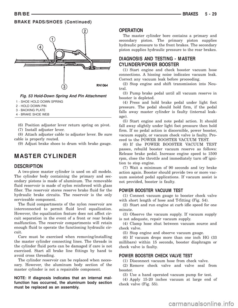
Fig. 53 Hold-Down Spring And Pin Attachment
1 - SHOE HOLD DOWN SPRING
2 - HOLD DOWN PIN
3 - BACKING PLATE
4 - BRAKE SHOE WEB
BR/BEBRAKES 5 - 29
BRAKE PADS/SHOES (Continued)
Page 402 of 2889
ket has swollen and prevents vent valve from open-
ing, replace cap.
Hold cap at eye level, upside down. If any light can
be seen between vent valve and rubber gasket,
replace cap.Do not use a replacement cap that
has a spring to hold vent shut.A replacement cap
must be the type designed for a coolant reserve/over-
flow system with a completely sealed diaphragm
spring and a rubber gasket. This gasket is used to
seal to radiator filler neck top surface. Use of proper
cap will allow coolant return to radiator.
WATER PUMP - 3.9L/5.2L/5.9L
DESCRIPTION
The water pump is located on the engine front
cover, and has an integral pulley attached (Fig. 46).
The water pump impeller is pressed onto the rear
of a shaft that rotates in a bearing pressed into the
water pump body. The body has a small hole for ven-
tilation. The water pump seals are lubricated by
antifreeze in the coolant mixture. Additional lubrica-
tion is not necessary.
OPERATION
A centrifugal water pump circulates coolant
through the water jackets, passages, intake manifold,
radiator core, cooling system hoses and heater core,
this coolant absorbs the heat generated when the
engine is running. The pump is driven by the engine
crankshaft via a drive belt.
DIAGNOSIS AND TESTINGÐWATER PUMP
A quick test to determine if pump is working is to
check if heater warms properly. A defective water
pump will not be able to circulate heated coolant
through the long heater hose to the heater core.
REMOVAL
The water pump on all models can be removed
without discharging the air conditioning system (if
equipped).
The water pump on all gas powered engines is
bolted directly to the engine timing chain case/cover.
On all 3.9L/5.2L/5.9L gas powered engines, a gas-
ket is used as a seal between the water pump and
timing chain case/cover.
If water pump is replaced because of bearing/shaft
damage or leaking shaft seal, the mechanical cooling
fan assembly should also be inspected. Inspect for
fatigue cracks, loose blades or loose rivets that could
have resulted from excessive vibration. Replace fan if
any of these conditions are found. Also check condi-
tion of the thermal viscous fan drive (Refer to 7 -
COOLING/ENGINE/FAN DRIVE VISCOUS
CLUTCH - DIAGNOSIS AND TESTING).
(1) Disconnect negative cable from battery.
(2) Drain cooling system (Refer to 7 - COOLING -
STANDARD PROCEDURE).
Do not waste reusable coolant. If solution is clean,
drain coolant into a clean container for reuse.
(3) Remove windshield washer reservoir tank from
radiator fan shroud.
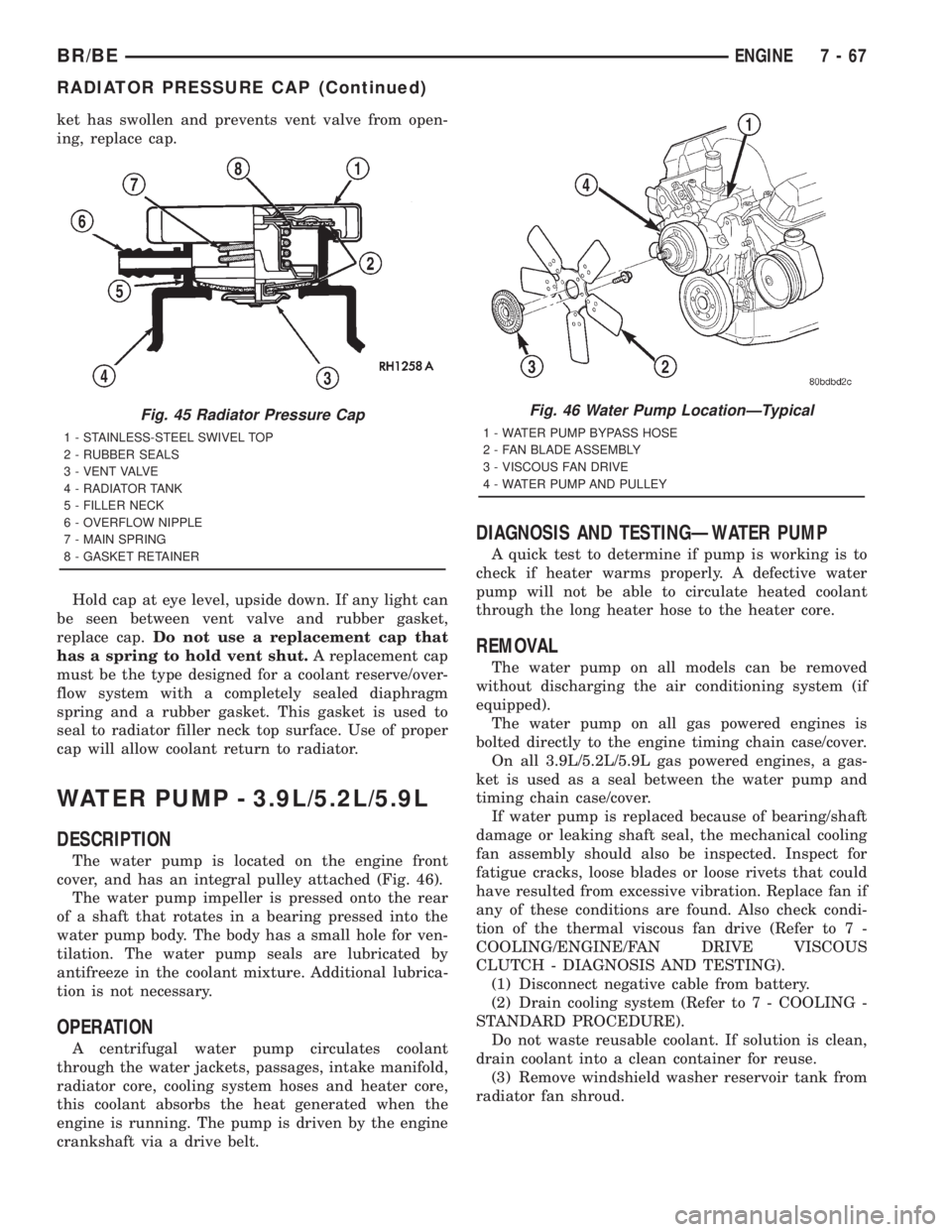
Fig. 45 Radiator Pressure Cap
1 - STAINLESS-STEEL SWIVEL TOP
2 - RUBBER SEALS
3 - VENT VALVE
4 - RADIATOR TANK
5 - FILLER NECK
6 - OVERFLOW NIPPLE
7 - MAIN SPRING
8 - GASKET RETAINER
Fig. 46 Water Pump LocationÐTypical
1 - WATER PUMP BYPASS HOSE
2 - FAN BLADE ASSEMBLY
3 - VISCOUS FAN DRIVE
4 - WATER PUMP AND PULLEY
BR/BEENGINE 7 - 67
RADIATOR PRESSURE CAP (Continued)
Page 416 of 2889
(2) Reinstall filler plug on Tool 6906B.
(3) Verify pump power switch is turned OFF. Con-
nect red alligator clip to positive (+) battery post.
Connect black (-) alligator clip to a good ground.
(4) Disconnect the cooler lines at the transmission.
NOTE: When flushing transmission cooler and
lines, ALWAYS reverse flush.
NOTE: The converter drainback valve must be
removed and an appropriate replacement hose
installed to bridge the space between the transmis-
sion cooler line and the cooler fitting. Failure to
remove the drainback valve will prevent reverse
flushing the system. A suitable replacement hose
can be found in the adapter kit supplied with the
flushing tool.
(5) Connect the BLUE pressure line to the OUT-
LET (From) cooler line.
(6) Connect the CLEAR return line to the INLET
(To) cooler line
(7) Remove the transmission oil cooler from the
vehicle. (Refer to 7 - COOLING/TRANSMISSION/
TRANS COOLER - REMOVAL)
(8) Remove the transmission oil cooler thermostat.
(Refer to 7 - COOLING/TRANSMISSION/TRANS
COOLER - DISASSEMBLY)
(9) Re-install the thermostat cover onto the oil
cooler and install the snap-ring.
(10) Re-connect the oil cooler to the transmission
cooler lines.
(11) Turn pump ON for two to three minutes to
flush cooler(s) and lines.
NOTE: This flushes the bypass circuit of the cooler
only.
(12) Turn pump OFF.
(13) Remove the thermostat cover from the oil
cooler.
(14) Install Special Tool Cooler Plug 8414 into the
transmission oil cooler.
(15) Re-install the thermostat cover onto the oil
cooler and install the snap-ring.
(16) Turn pump ON for two to three minutes to
flush cooler(s) and lines.
NOTE: This flushes the main oil cooler core pas-
sages only.
(17) Turn pump OFF.
(18) Remove the thermostat cover from the oil
cooler.
(19) Remove Special Tool Cooler Plug 8414 from
the transmission oil cooler.(20) Install a new thermostat spring, thermostat,
cover, and snap-ring into the transmission oil cooler.
(Refer to 7 - COOLING/TRANSMISSION/TRANS
COOLER - ASSEMBLY)
(21) Install the transmission oil cooler onto the
vehicle. (Refer to 7 - COOLING/TRANSMISSION/
TRANS COOLER - INSTALLATION)
(22) Disconnect CLEAR suction line from reservoir
at cover plate. Disconnect CLEAR return line at
cover plate, and place it in a drain pan.
(23) Turn pump ON for 30 seconds to purge flush-
ing solution from cooler and lines. Turn pump OFF.
(24) Place CLEAR suction line into a one quart
container of MopartATF +4, type 9602, Automatic
Transmission fluid.
(25) Turn pump ON until all transmission fluid is
removed from the one quart container and lines. This
purges any residual cleaning solvent from the trans-
mission cooler and lines. Turn pump OFF.
(26) Disconnect alligator clips from battery. Recon-
nect flusher lines to cover plate, and remove flushing
adapters from cooler lines.
REMOVAL
(1) Disconnect battery negative cable.
(2) Place a drain pan under the oil cooler lines.
(3) Disconnect the transmission oil cooler line
quick-connect fitting at the cooler outlet using the
quick connect release tool 6935. Loosen clamp from
inlet connection and slide hose off of nipple. Plug
cooler lines to prevent oil leakage.
(4) Remove the oil cooler lower mounting bolt (oil
cooler-to-vehicle body) (Fig. 2).
(5) Remove three bolts (radiator support bracket-
to-body) . Remove this A-shaped support bracket and
the transmission oil cooler as an assembly from the
vehicle. Take care not to damage the radiator core or
A/C condenser fins with the cooling lines when
removing.
(6) Remove oil cooler from A-shaped support
bracket by removing two upper mounting strap bolts
and mounting straps at support bracket (Fig. 2).
(7) Remove oil cooler from the A-shaped radiator
support bracket.
DISASSEMBLY
NOTE: The transmission oil cooler uses an internal
thermostat to control transmission oil flow through
the cooler. This thermostat is servicable.
(1) Remove the transmission oil cooler (Refer to 7 -
COOLING/TRANSMISSION/TRANS COOLER -
REMOVAL).
(2) Remove the snap ring retaining the thermostat
end plug (Fig. 3).
BR/BETRANSMISSION 7 - 81
TRANS COOLER - 3.9L/5.2L/5.9L (Continued)
Page 436 of 2889
²Wiper motor.
If the source of RFI or EMI noise is identified as a
component on the vehicle (i.e., generator, blower
motor, etc.), the ground path for that component
should be checked. If excessive resistance is found in
any ground circuit, clean, tighten, or repair the
ground circuits or connections to ground as required
before considering any component replacement.
For service and inspection of secondary ignition
components, refer to Electrical, Ignition Control.
Inspect the following secondary ignition system com-
ponents:
²Distributor cap and rotor
²Ignition coil
²Spark plugs
²Spark plug wire routing and condition.
Reroute the spark plug wires or replace the faulty
components as required.
If the source of the RFI or EMI noise is identified
as two-way mobile radio or telephone equipment,
check the equipment installation for the following:
²Power connections should be made directly to
the battery, and fused as closely to the battery as
possible.
²The antenna should be mounted on the roof or
toward the rear of the vehicle. Remember that mag-
netic antenna mounts on the roof panel can adversely
affect the operation of an overhead console compass,
if the vehicle is so equipped.
²The antenna cable should be fully shielded coax-
ial cable, should be as short as is practical, and
should be routed away from the factory-installed
vehicle wire harnesses whenever possible.
²The antenna and cable must be carefully
matched to ensure a low Standing Wave Ratio
(SWR).
Fleet vehicles are available with an extra-cost RFI-
suppressed Powertrain Control Module (PCM). This
unit reduces interference generated by the PCM on
some radio frequencies used in two-way radio com-
munications. However, this unit will not resolve com-
plaints of RFI in the commercial AM or FM radio
frequency ranges.
ENGINE-TO-BODY GROUND
STRAP
REMOVAL
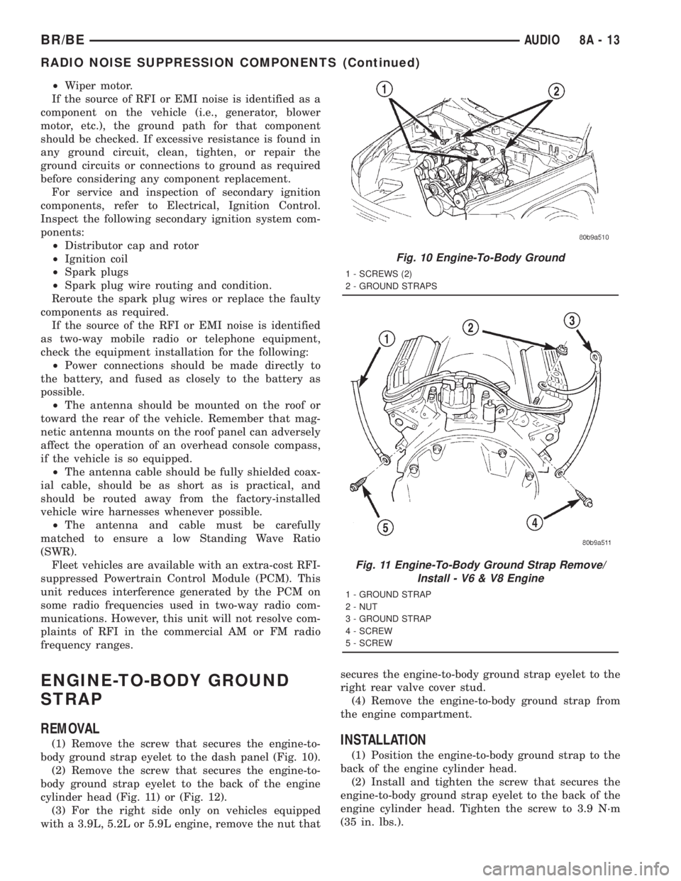
(1) Remove the screw that secures the engine-to-
body ground strap eyelet to the dash panel (Fig. 10).
(2) Remove the screw that secures the engine-to-
body ground strap eyelet to the back of the engine
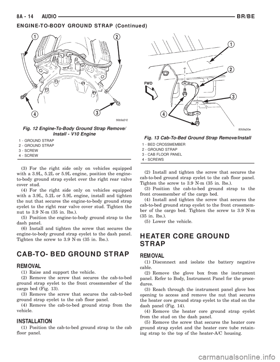
cylinder head (Fig. 11) or (Fig. 12).
(3) For the right side only on vehicles equipped
with a 3.9L, 5.2L or 5.9L engine, remove the nut thatsecures the engine-to-body ground strap eyelet to the
right rear valve cover stud.
(4) Remove the engine-to-body ground strap from
the engine compartment.INSTALLATION
(1) Position the engine-to-body ground strap to the
back of the engine cylinder head.
(2) Install and tighten the screw that secures the
engine-to-body ground strap eyelet to the back of the
engine cylinder head. Tighten the screw to 3.9 N´m
(35 in. lbs.).
Fig. 10 Engine-To-Body Ground
1 - SCREWS (2)
2 - GROUND STRAPS
Fig. 11 Engine-To-Body Ground Strap Remove/
Install - V6 & V8 Engine
1 - GROUND STRAP
2 - NUT
3 - GROUND STRAP
4 - SCREW
5 - SCREW
BR/BEAUDIO 8A - 13
RADIO NOISE SUPPRESSION COMPONENTS (Continued)
Page 437 of 2889
(3) For the right side only on vehicles equipped
with a 3.9L, 5.2L or 5.9L engine, position the engine-
to-body ground strap eyelet over the right rear valve
cover stud.
(4) For the right side only on vehicles equipped
with a 3.9L, 5.2L or 5.9L engine, install and tighten
the nut that secures the engine-to-body ground strap
eyelet to the right rear valve cover stud. Tighten the
nut to 3.9 N´m (35 in. lbs.).
(5) Position the engine-to-body ground strap to the
dash panel.
(6) Install and tighten the screw that secures the
engine-to-body ground strap eyelet to the dash panel.
Tighten the screw to 3.9 N´m (35 in. lbs.).
CAB-TO- BED GROUND STRAP
REMOVAL
(1) Raise and support the vehicle.
(2) Remove the screw that secures the cab-to-bed
ground strap eyelet to the front crossmember of the
cargo bed (Fig. 13).
(3) Remove the screw that secures the cab-to-bed
ground strap eyelet to the cab floor panel.
(4) Remove the cab-to-bed ground strap from the
vehicle.
INSTALLATION
(1) Position the cab-to-bed ground strap to the cab
floor panel.(2) Install and tighten the screw that secures the
cab-to-bed ground strap eyelet to the cab floor panel.
Tighten the screw to 3.9 N´m (35 in. lbs.).
(3) Position the cab-to-bed ground strap to the
front crossmember of the cargo bed.
(4) Install and tighten the screw that secures the
cab-to-bed ground strap eyelet to the front crossmem-
ber of the cargo bed. Tighten the screw to 3.9 N´m
(35 in. lbs.).
(5) Lower the vehicle.
HEATER CORE GROUND
STRAP
REMOVAL
(1) Disconnect and isolate the battery negative
cable.
(2) Remove the glove box from the instrument
panel. Refer to Body, Instrument Panel for the proce-
dures.
(3) Reach through the instrument panel glove box
opening to access and remove the nut that secures
the heater core ground strap eyelet to the stud on the
dash panel (Fig. 14).
(4) Remove the heater core ground strap eyelet
from the stud on the dash panel.
(5) Remove the screw that secures the heater core
ground strap eyelet and the heater core tube retain-
ing strap to the top of the heater-A/C housing.
Fig. 12 Engine-To-Body Ground Strap Remove/
Install - V10 Engine
1 - GROUND STRAP
2 - GROUND STRAP
3 - SCREW
4 - SCREWFig. 13 Cab-To-Bed Ground Strap Remove/Install
1 - BED CROSSMEMBER
2 - GROUND STRAP
3 - CAB FLOOR PANEL
4 - SCREWS
8A - 14 AUDIOBR/BE
ENGINE-TO-BODY GROUND STRAP (Continued)
Page 708 of 2889
(3) If vacuum is less than ten inches of mercury,
determine source of leak. Check vacuum line to
engine for leaks. Also check actual engine intake
manifold vacuum. If manifold vacuum does not meet
this requirement, check for poor engine performance
and repair as necessary.
(4) If vacuum line to engine is not leaking, check
for leak at vacuum reservoir. To locate and gain
access to reservoir, refer to Vacuum Reservoir Remov-
al/Installation in this group. Disconnect vacuum line
at reservoir and connect a hand-operated vacuum
pump to reservoir fitting. Apply vacuum. Reservoir
vacuum should not bleed off. If vacuum is being lost,
replace reservoir.
(5) Verify operation of one-way check valve and
check it for leaks.
(a) Locate one-way check valve. The valve is
located in vacuum line between vacuum reservoir
and engine vacuum source. Disconnect vacuum
hoses (lines) at each end of valve.
(b) Connect a hand-operated vacuum pump to
reservoir end of check valve. Apply vacuum. Vac-
uum should not bleed off. If vacuum is being lost,
replace one-way check valve.
(c) Connect a hand-operated vacuum pump to
vacuum source end of check valve. Apply vacuum.
Vacuum should flow through valve. If vacuum is
not flowing, replace one-way check valve. Seal the
fitting at opposite end of valve with a finger and
apply vacuum. If vacuum will not hold, diaphragm
within check valve has ruptured. Replace valve.
Diesel Engines With Automatic Trans.
On diesel powered engines equipped with an auto-
matic transmission: an engine driven vacuum pump,
a one-way check valve and vacuum lines are used to
supply vacuum to the speed control servo. A vacuum
reservoir is not used.
(1) Disconnect vacuum hose at speed control servo
and install a vacuum gauge into the disconnected
hose.
(2) Start engine and observe gauge at idle. For
vacuum testing and vacuum specifications, refer to
Vacuum Pump OutputÐDiesel Engine in 9, Engines.
(3) If vacuum pump output is OK, determine other
source of leak. Check all vacuum lines to: speed con-
trol servo, engine vacuum pump and heating/air con-
ditioning system for leaks.
(4) Verify operation of one-way check valve and
check it for leaks.(a) Locate one-way check valve. The valve is
located in vacuum line between speed control servo
and engine vacuum pump. Disconnect vacuum
hoses (lines) at each end of valve.
(b) Connect a hand-operated vacuum pump to
reservoir end of check valve. Apply vacuum. Vac-
uum should not bleed off. If vacuum is being lost,
replace one-way check valve.
(c) Connect a hand-operated vacuum pump to
vacuum source end of check valve. Apply vacuum.
Vacuum should flow through valve. If vacuum is
not flowing, replace one-way check valve. Seal the
fitting at opposite end of valve with a finger and
apply vacuum. If vacuum will not hold, diaphragm
within check valve has ruptured. Replace valve.
Diesel Engine With Manual Trans.
Vacuum is not used for any part of the speed con-
trol system if equipped with a diesel engine and a
manual transmission.
DIAGNOSIS AND TESTING - ROAD TEST
Perform a vehicle road test to verify reports of
speed control system malfunction. The road test
should include attention to the speedometer.
If a road test verifies a system problem and the
speedometer operates properly, check for:
²A Diagnostic Trouble Code (DTC). If a DTC
exists, conduct tests per the Powertrain Diagnostic
Procedures service manual.
²A misadjusted brake (stop) lamp switch. This
could also cause an intermittent problem.
²Loose, damaged or corroded electrical connec-
tions at the servo. Corrosion should be removed from
electrical terminals and a light coating of Mopar
MultiPurpose Grease, or equivalent, applied.
²Leaking vacuum reservoir.
²Loose or leaking vacuum hoses or connections.
²Defective one-way vacuum check valve.
²Secure attachment of both ends of the speed con-
trol servo cable.
²Smooth operation of throttle linkage and throttle
body air valve.
²Failed speed control servo. Do the servo vacuum
test.
CAUTION: When test probing for voltage or conti-
nuity at electrical connectors, care must be taken
not to damage connector, terminals or seals. If
these components are damaged, intermittent or
complete system failure may occur.
BR/BESPEED CONTROL 8P - 3
SPEED CONTROL (Continued)
Page 709 of 2889
SPECIFICATIONS
TORQUE - SPEED CONTROL SYSTEM
DESCRIPTION N-m Ft. Lbs. In. Lbs.
Servo Mounting Bracket
Nuts8.5 75
Switch Module Mounting
Screws326
Vacuum Reservoir
Mounting Screws2.2
20
CABLE
DESCRIPTION
The speed control servo cable is connected between
the speed control vacuum servo diaphragm and the
throttle body control linkage.
OPERATION
This cable causes the throttle control linkage to
open or close the throttle valve in response to move-
ment of the vacuum servo diaphragm.
REMOVAL - GAS ENGINES
(1) Disconnect negative battery cable at battery.
(2) Remove air cleaner (all except 8.0L V-10
engine).
(3) Using finger pressure only, remove speed con-
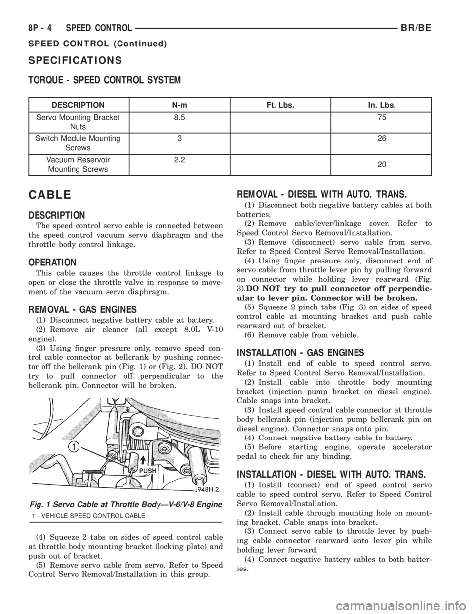
trol cable connector at bellcrank by pushing connec-
tor off the bellcrank pin (Fig. 1) or (Fig. 2). DO NOT
try to pull connector off perpendicular to the
bellcrank pin. Connector will be broken.
(4) Squeeze 2 tabs on sides of speed control cable
at throttle body mounting bracket (locking plate) and
push out of bracket.
(5) Remove servo cable from servo. Refer to Speed
Control Servo Removal/Installation in this group.
REMOVAL - DIESEL WITH AUTO. TRANS.
(1) Disconnect both negative battery cables at both
batteries.
(2) Remove cable/lever/linkage cover. Refer to
Speed Control Servo Removal/Installation.
(3) Remove (disconnect) servo cable from servo.
Refer to Speed Control Servo Removal/Installation.
(4) Using finger pressure only, disconnect end of
servo cable from throttle lever pin by pulling forward
on connector while holding lever rearward (Fig.
3).DO NOT try to pull connector off perpendic-
ular to lever pin. Connector will be broken.
(5) Squeeze 2 pinch tabs (Fig. 3) on sides of speed
control cable at mounting bracket and push cable
rearward out of bracket.
(6) Remove cable from vehicle.
INSTALLATION - GAS ENGINES
(1) Install end of cable to speed control servo.
Refer to Speed Control Servo Removal/Installation.
(2) Install cable into throttle body mounting
bracket (injection pump bracket on diesel engine).
Cable snaps into bracket.
(3) Install speed control cable connector at throttle
body bellcrank pin (injection pump bellcrank pin on
diesel engine). Connector snaps onto pin.
(4) Connect negative battery cable to battery.
(5) Before starting engine, operate accelerator
pedal to check for any binding.
INSTALLATION - DIESEL WITH AUTO. TRANS.
(1) Install (connect) end of speed control servo
cable to speed control servo. Refer to Speed Control
Servo Removal/Installation.
(2) Install cable through mounting hole on mount-
ing bracket. Cable snaps into bracket.
(3) Connect servo cable to throttle lever by push-
ing cable connector rearward onto lever pin while
holding lever forward.
(4) Connect negative battery cables to both batter-
ies.
Fig. 1 Servo Cable at Throttle BodyÐV-6/V-8 Engine
1 - VEHICLE SPEED CONTROL CABLE
8P - 4 SPEED CONTROLBR/BE
SPEED CONTROL (Continued)