2001 DODGE RAM check oil
[x] Cancel search: check oilPage 2017 of 2889
INSPECTION
Check condition of the seal rings and thrust
washer on the reaction shaft support. The seal rings
do not need to be replaced unless cracked, broken, or
severely worn.
Inspect the pump and support components. Replace
the pump or support if the seal ring grooves or
machined surfaces are worn, scored, pitted, or dam-
aged. Replace the pump gears if pitted, worn
chipped, or damaged.
Inspect the pump bushing. Then check the reaction
shaft support bushing. Replace either bushing only if
heavily worn, scored or damaged. It is not necessary to
replace the bushings unless they are actually damaged.
Clearance between outer gear and reaction shaft
housing should be 0.010 to 0.063 mm (0.0004 to 0.0025
in.). Clearance between inner gear and reaction shaft
housing should be 0.010 to 0.063 mm (0.0004 to 0.0025
in.). Both clearances can be measured at the same time
by installing the gears in the pump body and measure
pump component clearances as follows:
(1) Position an appropriate piece of PlastigageŸ
across both gears.
(2) Align the plastigage to a flat area on the reac-
tion shaft housing.
(3) Install the reaction shaft to the pump housing.
(4) Separate the reaction shaft housing from the
pump housing and measure the PlastigageŸ follow-
ing the instructions supplied with it.
Clearance between inner gear tooth and outer gear
should be 0.08 to 0.19 mm (0.0035 to 0.0075 in.).
Measure clearance with an appropriate feeler gauge.Clearance between outer gear and pump housing
should be 0.10 to 0.19 mm (0.004 to 0.0075 in.). Mea-
sure clearance with an appropriate feeler gauge.
ASSEMBLY
(1) Lubricate gear bore in pump housing with
transmission fluid.
(2) Lubricate pump gears with transmission fluid.
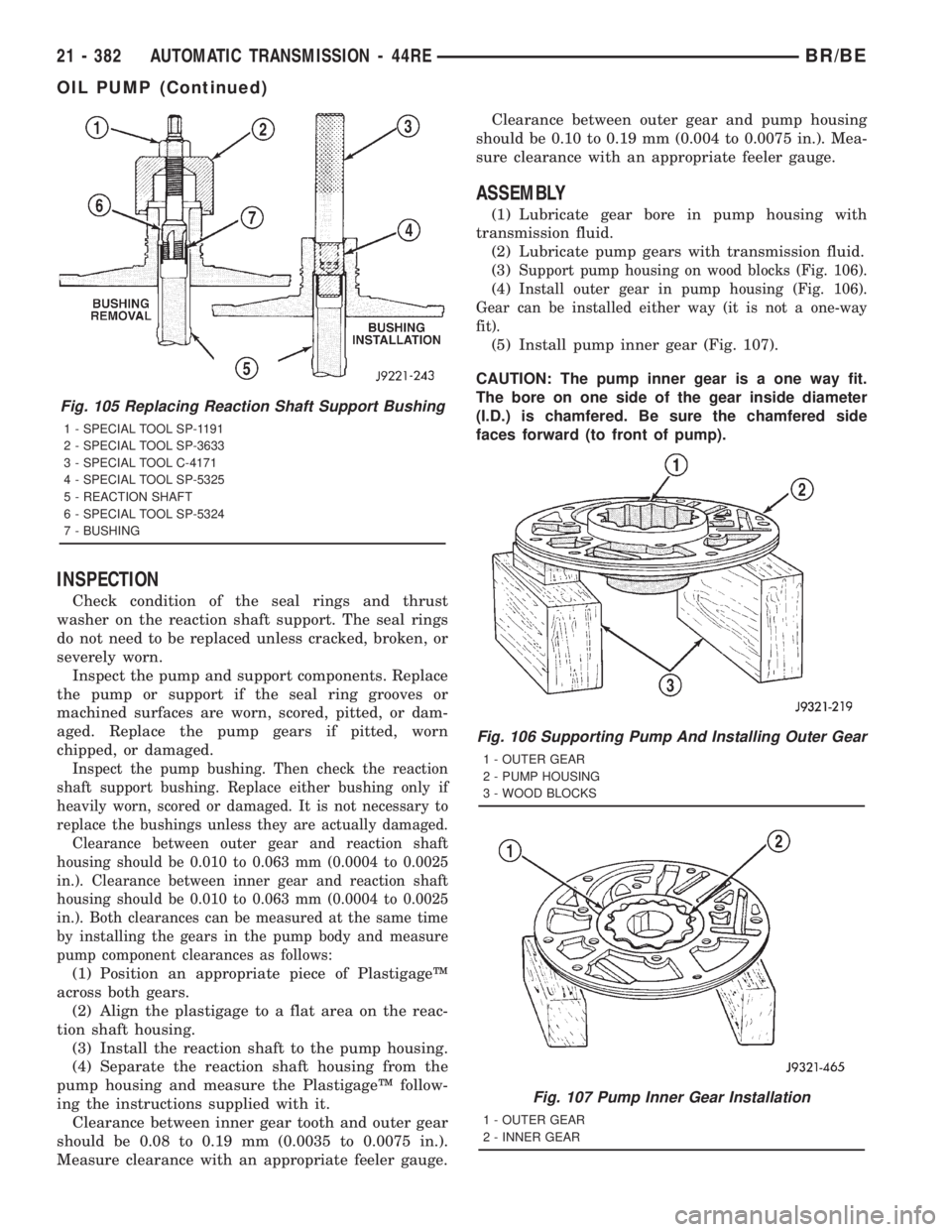
(3)
Support pump housing on wood blocks (Fig. 106).
(4)Install outer gear in pump housing (Fig. 106).
Gear can be installed either way (it is not a one-way
fit).
(5) Install pump inner gear (Fig. 107).
CAUTION: The pump inner gear is a one way fit.
The bore on one side of the gear inside diameter
(I.D.) is chamfered. Be sure the chamfered side
faces forward (to front of pump).
Fig. 105 Replacing Reaction Shaft Support Bushing
1 - SPECIAL TOOL SP-1191
2 - SPECIAL TOOL SP-3633
3 - SPECIAL TOOL C-4171
4 - SPECIAL TOOL SP-5325
5 - REACTION SHAFT
6 - SPECIAL TOOL SP-5324
7 - BUSHING
Fig. 106 Supporting Pump And Installing Outer Gear
1 - OUTER GEAR
2 - PUMP HOUSING
3 - WOOD BLOCKS
Fig. 107 Pump Inner Gear Installation
1 - OUTER GEAR
2 - INNER GEAR
21 - 382 AUTOMATIC TRANSMISSION - 44REBR/BE
OIL PUMP (Continued)
Page 2058 of 2889
ADJUSTMENT
Check linkage adjustment by starting engine in
PARK and NEUTRAL. Adjustment is acceptable if
the engine starts in only these two positions. Adjust-
ment is incorrect if the engine starts in one position
but not both positions
If the engine starts in any other position, or if the
engine will not start in any position, the park/neutral
switch is probably faulty.
LINKAGE ADJUSTMENT
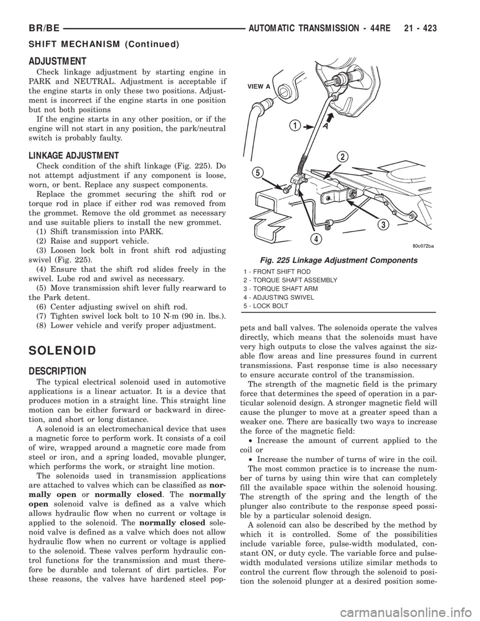
Check condition of the shift linkage (Fig. 225). Do
not attempt adjustment if any component is loose,
worn, or bent. Replace any suspect components.
Replace the grommet securing the shift rod or
torque rod in place if either rod was removed from
the grommet. Remove the old grommet as necessary
and use suitable pliers to install the new grommet.
(1) Shift transmission into PARK.
(2) Raise and support vehicle.
(3) Loosen lock bolt in front shift rod adjusting
swivel (Fig. 225).
(4) Ensure that the shift rod slides freely in the
swivel. Lube rod and swivel as necessary.
(5) Move transmission shift lever fully rearward to
the Park detent.
(6) Center adjusting swivel on shift rod.
(7) Tighten swivel lock bolt to 10 N´m (90 in. lbs.).
(8) Lower vehicle and verify proper adjustment.
SOLENOID
DESCRIPTION
The typical electrical solenoid used in automotive
applications is a linear actuator. It is a device that
produces motion in a straight line. This straight line
motion can be either forward or backward in direc-
tion, and short or long distance.
A solenoid is an electromechanical device that uses
a magnetic force to perform work. It consists of a coil
of wire, wrapped around a magnetic core made from
steel or iron, and a spring loaded, movable plunger,
which performs the work, or straight line motion.
The solenoids used in transmission applications
are attached to valves which can be classified asnor-
mally openornormally closed. Thenormally
opensolenoid valve is defined as a valve which
allows hydraulic flow when no current or voltage is
applied to the solenoid. Thenormally closedsole-
noid valve is defined as a valve which does not allow
hydraulic flow when no current or voltage is applied
to the solenoid. These valves perform hydraulic con-
trol functions for the transmission and must there-
fore be durable and tolerant of dirt particles. For
these reasons, the valves have hardened steel pop-pets and ball valves. The solenoids operate the valves
directly, which means that the solenoids must have
very high outputs to close the valves against the siz-
able flow areas and line pressures found in current
transmissions. Fast response time is also necessary
to ensure accurate control of the transmission.
The strength of the magnetic field is the primary
force that determines the speed of operation in a par-
ticular solenoid design. A stronger magnetic field will
cause the plunger to move at a greater speed than a
weaker one. There are basically two ways to increase
the force of the magnetic field:
²Increase the amount of current applied to the
coil or
²Increase the number of turns of wire in the coil.
The most common practice is to increase the num-
ber of turns by using thin wire that can completely
fill the available space within the solenoid housing.
The strength of the spring and the length of the
plunger also contribute to the response speed possi-
ble by a particular solenoid design.
A solenoid can also be described by the method by
which it is controlled. Some of the possibilities
include variable force, pulse-width modulated, con-
stant ON, or duty cycle. The variable force and pulse-
width modulated versions utilize similar methods to
control the current flow through the solenoid to posi-
tion the solenoid plunger at a desired position some-
Fig. 225 Linkage Adjustment Components
1 - FRONT SHIFT ROD
2 - TORQUE SHAFT ASSEMBLY
3 - TORQUE SHAFT ARM
4 - ADJUSTING SWIVEL
5 - LOCK BOLT
BR/BEAUTOMATIC TRANSMISSION - 44RE 21 - 423
SHIFT MECHANISM (Continued)
Page 2067 of 2889
TORQUE CONVERTER CLUTCH (TCC)
The torque converter clutch is hydraulically
applied and is released when fluid is vented from the
hydraulic circuit by the torque converter control
(TCC) solenoid on the valve body. The torque con-
verter clutch is controlled by the Powertrain Control
Module (PCM). The torque converter clutch engages
in fourth gear, and in third gear under various con-
ditions, such as when the O/D switch is OFF, when
the vehicle is cruising on a level surface after the
vehicle has warmed up. The torque converter clutch
will disengage momentarily when an increase in
engine load is sensed by the PCM, such as when the
vehicle begins to go uphill or the throttle pressure is
increased.
REMOVAL
(1) Remove transmission and torque converter
from vehicle.
(2) Place a suitable drain pan under the converter
housing end of the transmission.
CAUTION: Verify that transmission is secure on the
lifting device or work surface, the center of gravity
of the transmission will shift when the torque con-
verter is removed creating an unstable condition.
The torque converter is a heavy unit. Use caution
when separating the torque converter from the
transmission.
(3) Pull the torque converter forward until the cen-
ter hub clears the oil pump seal.
(4) Separate the torque converter from the trans-
mission.
INSTALLATION
Check converter hub and drive notches for sharp
edges, burrs, scratches, or nicks. Polish the hub and
notches with 320/400 grit paper or crocus cloth if nec-
essary. The hub must be smooth to avoid damaging
the pump seal at installation.
(1) Lubricate oil pump seal lip with transmission
fluid.
(2) Place torque converter in position on transmis-
sion.
CAUTION: Do not damage oil pump seal or bushing
while inserting torque converter into the front of the
transmission.
(3) Align torque converter to oil pump seal open-
ing.
(4) Insert torque converter hub into oil pump.
(5) While pushing torque converter inward, rotate
converter until converter is fully seated in the oil
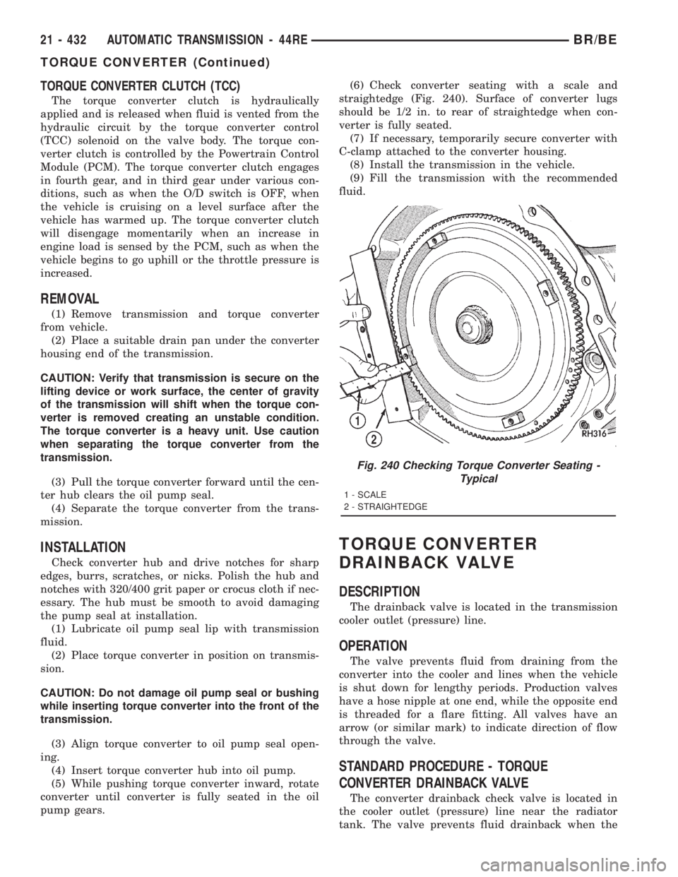
pump gears.(6) Check converter seating with a scale and
straightedge (Fig. 240). Surface of converter lugs
should be 1/2 in. to rear of straightedge when con-
verter is fully seated.
(7) If necessary, temporarily secure converter with
C-clamp attached to the converter housing.
(8) Install the transmission in the vehicle.
(9) Fill the transmission with the recommended
fluid.
TORQUE CONVERTER
DRAINBACK VALVE
DESCRIPTION
The drainback valve is located in the transmission
cooler outlet (pressure) line.
OPERATION
The valve prevents fluid from draining from the
converter into the cooler and lines when the vehicle
is shut down for lengthy periods. Production valves
have a hose nipple at one end, while the opposite end
is threaded for a flare fitting. All valves have an
arrow (or similar mark) to indicate direction of flow
through the valve.
STANDARD PROCEDURE - TORQUE
CONVERTER DRAINBACK VALVE
The converter drainback check valve is located in
the cooler outlet (pressure) line near the radiator
tank. The valve prevents fluid drainback when the
Fig. 240 Checking Torque Converter Seating -
Typical
1 - SCALE
2 - STRAIGHTEDGE
21 - 432 AUTOMATIC TRANSMISSION - 44REBR/BE
TORQUE CONVERTER (Continued)
Page 2073 of 2889
OPERATION
NOTE: Refer to the Hydraulic Schematics for a
visual aid in determining valve location, operation
and design.
CHECK BALLS
CHECK BALL NUMBER DESCRIPTION
1 Allows either the manual valve to put line pressure on the 1-2 governor plug or
the KD Valve to put WOT line pressure on the 1-2 governor plug.
2 Allows either the manual valve to put line pressure on the 2-3 governor plug or
the KD Valve to put WOT line pressure on the 2-3 governor plug.
3 Allows either the Reverse circuit or the 3rd gear circuit to pressurize the front
clutch.
4 Allows either the Manual Low circuit from the Manual Valve or the Reverse
from the Manual Valve circuit to pressurize the rear servo.
5 Directs line pressure to the spring end of the 2-3 shift valve in either Manual
Low or Manual 2nd, forcing the downshift to 2nd gear regardless of governor
pressure.
6 Provides a by-pass around the front servo orifice so that the servo can release
quickly.
7 Provides a by-pass around the rear clutch orifice so that the clutch can release
quickly.
8 Directs reverse line pressure through an orifice to the throttle valve eliminating
the extra leakage and insuring that Reverse line pressure pressure will be
sufficient.
9 Provides a by-pass around the rear servo orifice so that the servo can release
quickly.
ECE (10) Allows the lockup clutch to used at WOT in 3rd gear by putting line pressure
from the 3-4 Timing Valve on the interlock area of the 2-3 shift valve, thereby
preventing a 3rd gear Lock-up to 2nd gear kickdown.
REGULATOR VALVE
The pressure regulator valve is needed to control
the hydraulic pressure within the system and reduce
the amount of heat produced in the fluid. The pres-
sure regulator valve is located in the valve body near
the manual valve. The pressure regulator valve train
controls the maximum pressure in the lines by
metering the dumping of fluid back into the sump.
Regulated pressure is referred to as ªline pressure.º
The regulator valve (Fig. 246) has a spring on one
end that pushes the valve to the left. This closes a
dump (vent) that is used to lower pressure. The clos-
ing of the dump will cause the oil pressure to
increase. Oil pressure on the opposite end of thevalve pushes the valve to the right, opening the
dump and lowering oil pressure. The result is spring
pressure working against oil pressure to maintain
the oil at specific pressures. With the engine run-
ning, fluid flows from the pump to the pressure reg-
ulator valve, manual valve, and the interconnected
circuits. As fluid is sent through passages to the reg-
ulator valve, the pressure pushes the valve to the
right against the large spring. It is also sent to the
reaction areas on the left side of the throttle pressure
plug and the line pressure plug. With the gear selec-
tor in the PARK position, fluid recirculates through
the regulator and manual valves back to the sump.
21 - 438 AUTOMATIC TRANSMISSION - 44REBR/BE
VALVE BODY (Continued)
Page 2100 of 2889
CLEANING
Clean the valve housings, valves, plugs, springs,
and separator plates with a standard parts cleaning
solution only. Do not use gasoline, kerosene, or any
type of caustic solution.
Do not immerse any of the electrical components in
cleaning solution. Clean the governor solenoid and
sensor and the dual solenoid and harness assembly
by wiping them off with dry shop towels only.
Dry all except the electrical parts with compressed
air. Make sure all passages are clean and free from
obstructions.Do not use rags or shop towels to
dry or wipe off valve body components. Lint
from these materials can stick to valve body
parts, interfere with valve operation, and clog
filters and fluid passages.
Wipe the governor pressure sensor and solenoid
valve with dry, lint free shop towels only. The O-rings
on the sensor and solenoid valve are the only service-
able components. Be sure the vent ports in the sole-
noid valve are open and not blocked by dirt or debris.
Replace the valve and/or sensor only when DRB scan
tool diagnosis indicates this is necessary. Or, if either
part has sustained physical damage (dented,
deformed, broken, etc.).
CAUTION: Do not turn the small screw at the end of
the solenoid valve for any reason. Turning the
screw in either direction will ruin solenoid calibra-
tion and result in solenoid failure. In addition, the
filter on the solenoid valve is NOT serviceable. Do
not try to remove the filter as this will damage the
valve housing.
INSPECTION
Inspect the throttle and manual valve levers and
shafts. Do not attempt to straighten a bent shaft or
correct a loose lever. Replace these components if
worn, bent, loose or damaged in any way.
Inspect all of the valve body mating surfaces for
scratches, nicks, burrs, or distortion. Use a straight-
edge to check surface flatness. Minor scratches may
be removed with crocus cloth using only very light
pressure.
Minor distortion of a valve body mating surface
may be corrected by smoothing the surface with a
sheet of crocus cloth. Position the crocus cloth on a
surface plate, sheet of plate glass or equally flat sur-
face. If distortion is severe or any surfaces are
heavily scored, the valve body will have to be
replaced.
CAUTION: Many of the valves and plugs, such as
the throttle valve, shuttle valve plug, 1-2 shift valve
and 1-2 governor plug, are made of coated alumi-
num. Aluminum components are identified by the
dark color of the special coating applied to the sur-
face (or by testing with a magnet). Do not sand alu-
minum valves or plugs under any circumstances.
This practice could damage the special coating
causing the valves/plugs to stick and bind.
Inspect the valves and plugs for scratches, burrs,
nicks, or scores. Minor surface scratches on steel
valves and plugs can be removed with crocus cloth
butdo not round off the edges of the valve or
plug lands.Maintaining sharpness of these edges is
vitally important. The edges prevent foreign matter
from lodging between the valves and plugs and the
bore.
Inspect all the valve and plug bores in the valve
body. Use a penlight to view the bore interiors.
Replace the valve body if any bores are distorted or
scored. Inspect all of the valve body springs. The
springs must be free of distortion, warpage or broken
coils.
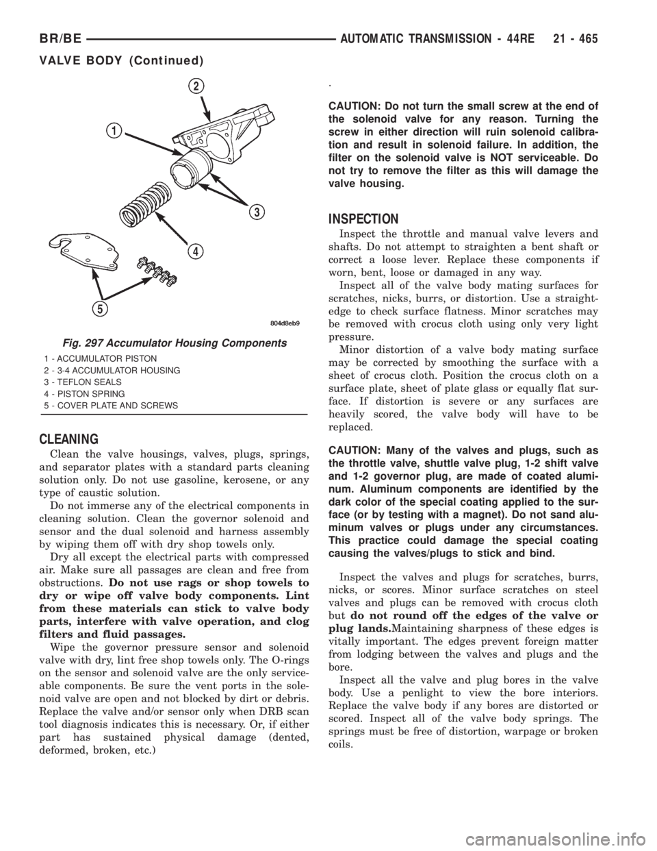
Fig. 297 Accumulator Housing Components
1 - ACCUMULATOR PISTON
2 - 3-4 ACCUMULATOR HOUSING
3 - TEFLON SEALS
4 - PISTON SPRING
5 - COVER PLATE AND SCREWS
BR/BEAUTOMATIC TRANSMISSION - 44RE 21 - 465
VALVE BODY (Continued)
Page 2110 of 2889
INSTALLATION
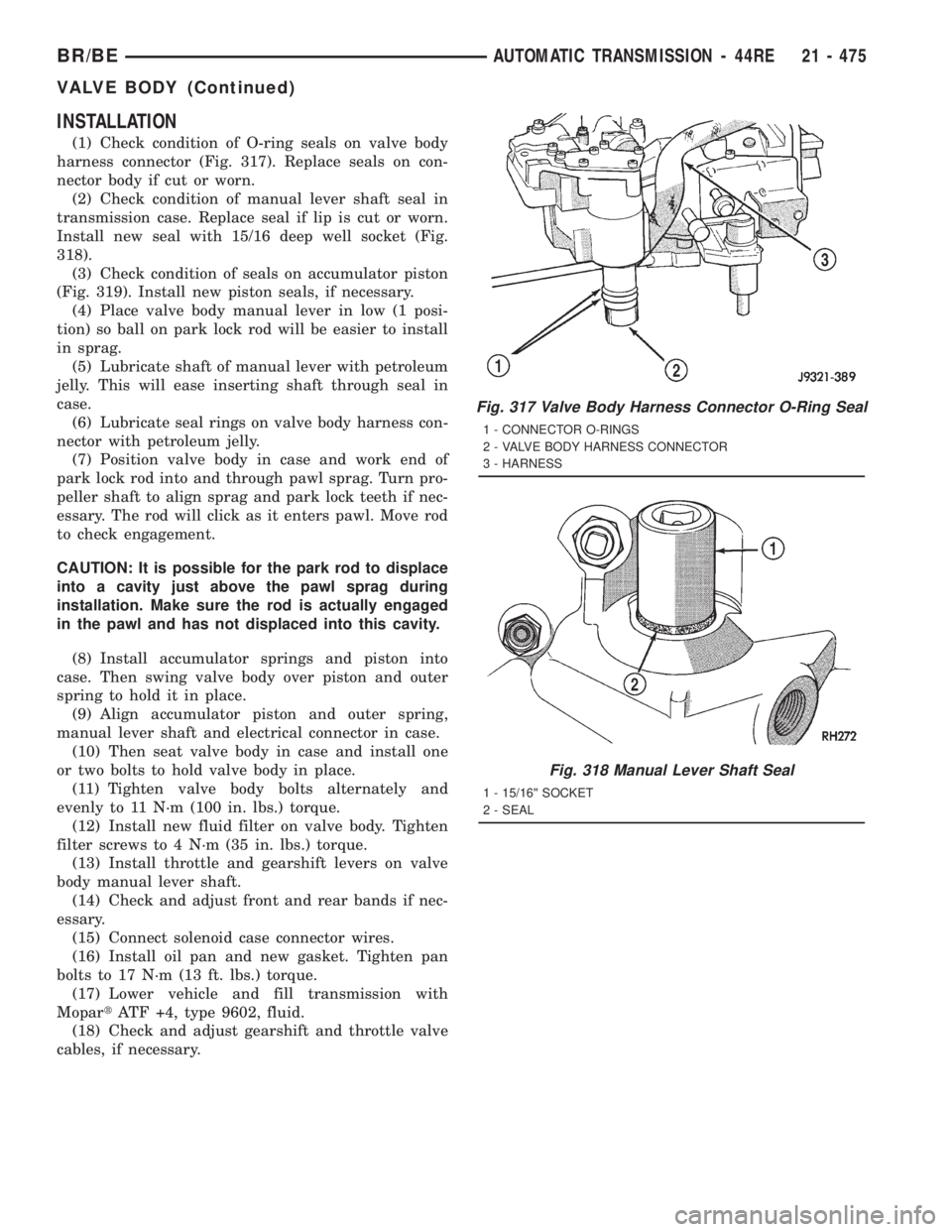
(1) Check condition of O-ring seals on valve body
harness connector (Fig. 317). Replace seals on con-
nector body if cut or worn.
(2) Check condition of manual lever shaft seal in
transmission case. Replace seal if lip is cut or worn.
Install new seal with 15/16 deep well socket (Fig.
318).
(3) Check condition of seals on accumulator piston
(Fig. 319). Install new piston seals, if necessary.
(4) Place valve body manual lever in low (1 posi-
tion) so ball on park lock rod will be easier to install
in sprag.
(5) Lubricate shaft of manual lever with petroleum
jelly. This will ease inserting shaft through seal in
case.
(6) Lubricate seal rings on valve body harness con-
nector with petroleum jelly.
(7) Position valve body in case and work end of
park lock rod into and through pawl sprag. Turn pro-
peller shaft to align sprag and park lock teeth if nec-
essary. The rod will click as it enters pawl. Move rod
to check engagement.
CAUTION: It is possible for the park rod to displace
into a cavity just above the pawl sprag during
installation. Make sure the rod is actually engaged
in the pawl and has not displaced into this cavity.
(8) Install accumulator springs and piston into
case. Then swing valve body over piston and outer
spring to hold it in place.
(9) Align accumulator piston and outer spring,
manual lever shaft and electrical connector in case.
(10) Then seat valve body in case and install one
or two bolts to hold valve body in place.
(11) Tighten valve body bolts alternately and
evenly to 11 N´m (100 in. lbs.) torque.
(12) Install new fluid filter on valve body. Tighten
filter screws to 4 N´m (35 in. lbs.) torque.
(13) Install throttle and gearshift levers on valve
body manual lever shaft.
(14) Check and adjust front and rear bands if nec-
essary.
(15) Connect solenoid case connector wires.
(16) Install oil pan and new gasket. Tighten pan
bolts to 17 N´m (13 ft. lbs.) torque.
(17) Lower vehicle and fill transmission with
MopartATF +4, type 9602, fluid.
(18) Check and adjust gearshift and throttle valve
cables, if necessary.
Fig. 317 Valve Body Harness Connector O-Ring Seal
1 - CONNECTOR O-RINGS
2 - VALVE BODY HARNESS CONNECTOR
3 - HARNESS
Fig. 318 Manual Lever Shaft Seal
1 - 15/16©© SOCKET
2 - SEAL
BR/BEAUTOMATIC TRANSMISSION - 44RE 21 - 475
VALVE BODY (Continued)
Page 2112 of 2889
AUTOMATIC TRANSMISSION - 46RE
TABLE OF CONTENTS
page page
AUTOMATIC TRANSMISSION - 46RE
DESCRIPTION..........................478
OPERATION............................480
DIAGNOSIS AND TESTING................486
AUTOMATIC TRANSMISSION.............486
PRELIMINARY........................486
ROAD TESTING.......................486
HYDRAULIC PRESSURE TEST...........487
AIR TESTING TRANSMISSION CLUTCH
AND BAND OPERATION.................490
CONVERTER HOUSING FLUID LEAK......491
DIAGNOSIS CHARTS...................492
STANDARD PROCEDURE.................502
ALUMINUM THREAD REPAIR.............502
REMOVAL.............................502
DISASSEMBLY..........................503
CLEANING.............................509
INSPECTION...........................510
ASSEMBLY............................510
INSTALLATION..........................518
SCHEMATICS AND DIAGRAMS.............520
SPECIFICATIONS........................532
SPECIAL TOOLS........................534
ACCUMULATOR
DESCRIPTION..........................537
OPERATION............................537
INSPECTION...........................538
BANDS
DESCRIPTION..........................538
OPERATION............................539
ADJUSTMENTS.........................539
ELECTRONIC GOVERNOR
DESCRIPTION..........................540
OPERATION............................541
REMOVAL.............................542
INSTALLATION..........................543
EXTENSION HOUSING BUSHING
REMOVAL.............................544
INSTALLATION..........................544
EXTENSION HOUSING SEAL
REMOVAL.............................544
INSTALLATION..........................544
FLUID AND FILTER
DIAGNOSIS AND TESTING................545
EFFECTS OF INCORRECT FLUID LEVEL . . . 545
CAUSES OF BURNT FLUID..............545
FLUID CONTAMINATION................545
STANDARD PROCEDURE.................545
FLUID LEVEL CHECK...................545FLUID AND FILTER REPLACEMENT.......547
TRANSMISSION FILL...................547
FRONT CLUTCH
DESCRIPTION..........................548
OPERATION............................548
DISASSEMBLY..........................549
INSPECTION...........................550
ASSEMBLY............................550
FRONT SERVO
DESCRIPTION..........................551
OPERATION............................552
DISASSEMBLY..........................552
CLEANING.............................552
INSPECTION...........................553
ASSEMBLY............................553
OIL PUMP
DESCRIPTION..........................554
OPERATION............................554
STANDARD PROCEDURE.................554
OIL PUMP VOLUME CHECK..............554
DISASSEMBLY..........................555
CLEANING.............................557
INSPECTION...........................557
ASSEMBLY............................558
OUTPUT SHAFT FRONT BEARING
REMOVAL.............................559
INSTALLATION..........................560
OUTPUT SHAFT REAR BEARING
REMOVAL.............................560
INSTALLATION..........................560
OVERDRIVE CLUTCH
DESCRIPTION..........................560
OPERATION............................560
OVERDRIVE UNIT
REMOVAL.............................560
DISASSEMBLY..........................562
CLEANING.............................568
INSPECTION...........................569
ASSEMBLY............................569
INSTALLATION..........................577
OVERDRIVE SWITCH
DESCRIPTION..........................578
OPERATION............................579
DIAGNOSIS AND TESTING................579
OVERDRIVE ELECTRICAL CONTROLS.....579
REMOVAL.............................579
INSTALLATION..........................579
BR/BEAUTOMATIC TRANSMISSION - 46RE 21 - 477
Page 2121 of 2889

FOURTH GEAR POWERFLOW
Fourth gear overdrive range is electronically con-
trolled and hydraulically activated. Various sensor
inputs are supplied to the powertrain control module
to operate the overdrive solenoid on the valve body.
The solenoid contains a check ball that opens and
closes a vent port in the 3-4 shift valve feed passage.
The overdrive solenoid (and check ball) are not ener-
gized in first, second, third, or reverse gear. The vent
port remains open, diverting line pressure from the
2-3 shift valve away from the 3-4 shift valve. The
overdrive control switch must be in the ON position
to transmit overdrive status to the PCM. A 3-4
upshift occurs only when the overdrive solenoid is
energized by the PCM. The PCM energizes the over-
drive solenoid during the 3-4 upshift. This causes the
solenoid check ball to close the vent port allowing
line pressure from the 2-3 shift valve to act directly
on the 3-4 upshift valve. Line pressure on the 3-4
shift valve overcomes valve spring pressure moving
the valve to the upshift position. This action exposes
the feed passages to the 3-4 timing valve, 3-4 quick
fill valve, 3-4 accumulator, and ultimately to the
overdrive piston. Line pressure through the timing
valve moves the overdrive piston into contact with
the overdrive clutch. The direct clutch is disengaged
before the overdrive clutch is engaged. The boost
valve provides increased fluid apply pressure to the
overdrive clutch during 3-4 upshifts, and when accel-
erating in fourth gear. The 3-4 accumulator cushions
overdrive clutch engagement to smooth 3-4 upshifts.
The accumulator is charged at the same time as
apply pressure acts against the overdrive piston.
DIAGNOSIS AND TESTING - AUTOMATIC
TRANSMISSION
Automatic transmission problems can be a result of
poor engine performance, incorrect fluid level, incor-
rect linkage or cable adjustment, band or hydraulic
control pressure adjustments, hydraulic system mal-
functions or electrical/mechanical component mal-
functions. Begin diagnosis by checking the easily
accessible items such as: fluid level and condition,
linkage adjustments and electrical connections. A
road test will determine if further diagnosis is neces-
sary.
DIAGNOSIS AND TESTING - PRELIMINARY
Two basic procedures are required. One procedure
for vehicles that are drivable and an alternate proce-
dure for disabled vehicles (will not back up or move
forward).
VEHICLE IS DRIVEABLE
(1) Check for transmission fault codes using DRBt
scan tool.(2) Check fluid level and condition.
(3) Adjust throttle and gearshift linkage if com-
plaint was based on delayed, erratic, or harsh shifts.
(4) Road test and note how transmission upshifts,
downshifts, and engages.
(5) Perform hydraulic pressure test if shift prob-
lems were noted during road test.
(6) Perform air-pressure test to check clutch-band
operation.
VEHICLE IS DISABLED
(1) Check fluid level and condition.
(2) Check for broken or disconnected gearshift or
throttle linkage.
(3) Check for cracked, leaking cooler lines, or loose
or missing pressure-port plugs.
(4) Raise and support vehicle on safety stands,
start engine, shift transmission into gear, and note
following:
(a) If propeller shaft turns but wheels do not,
problem is with differential or axle shafts.
(b) If propeller shaft does not turn and transmis-
sion is noisy, stop engine. Remove oil pan, and
check for debris. If pan is clear, remove transmis-
sion and check for damaged drive plate, converter,
oil pump, or input shaft.
(c) If propeller shaft does not turn and transmis-
sion is not noisy, perform hydraulic-pressure test to
determine if problem is hydraulic or mechanical.
DIAGNOSIS AND TESTING - ROAD TESTING
Before road testing, be sure the fluid level and con-
trol cable adjustments have been checked and
adjusted if necessary. Verify that diagnostic trouble
codes have been resolved.
Observe engine performance during the road test.
A poorly tuned engine will not allow accurate analy-
sis of transmission operation.
Operate the transmission in all gear ranges. Check
for shift variations and engine flare which indicates
slippage. Note if shifts are harsh, spongy, delayed,
early, or if part throttle downshifts are sensitive.
Slippage indicated by engine flare, usually means
clutch, band or overrunning clutch problems. If the
condition is advanced, an overhaul will be necessary
to restore normal operation.
A slipping clutch or band can often be determined
by comparing which internal units are applied in the
various gear ranges. The Clutch and Band Applica-
tion chart provides a basis for analyzing road test
results.
21 - 486 AUTOMATIC TRANSMISSION - 46REBR/BE
AUTOMATIC TRANSMISSION - 46RE (Continued)