2001 DODGE RAM diagram
[x] Cancel search: diagramPage 506 of 2889
(4) Verify that all lamps and accessories are
turned off.
(5) To prevent a gasoline engine from starting,
remove Automatic ShutDown (ASD) relay. To prevent
a diesel engine from starting, remove Fuel Pump
Relay. These relays are located in Power Distribution
Center (PDC). Refer to label on PDC cover for relay
location.
WARNING: IF EQUIPPED WITH DIESEL ENGINE,
ATTEMPT TO START ENGINE A FEW TIMES
BEFORE PROCEEDING WITH FOLLOWING STEP.
(6) Rotate and hold ignition switch in Start posi-
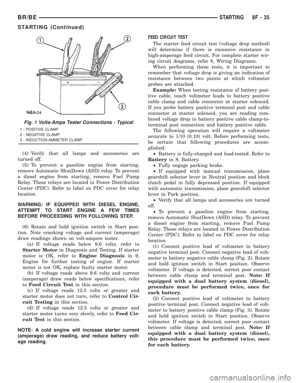
tion. Note cranking voltage and current (amperage)
draw readings shown on volt-ampere tester.
(a) If voltage reads below 9.6 volts, refer to
Starter Motorin Diagnosis and Testing. If starter
motor is OK, refer toEngine Diagnosisin 9,
Engine for further testing of engine. If starter
motor is not OK, replace faulty starter motor.
(b) If voltage reads above 9.6 volts and current
(amperage) draw reads below specifications, refer
toFeed Circuit Testin this section.
(c) If voltage reads 12.5 volts or greater and
starter motor does not turn, refer toControl Cir-
cuit Testingin this section.
(d) If voltage reads 12.5 volts or greater and
starter motor turns very slowly, refer toFeed Cir-
cuit Testin this section.
NOTE: A cold engine will increase starter current
(amperage) draw reading, and reduce battery volt-
age reading.FEED CIRCUIT TEST
The starter feed circuit test (voltage drop method)
will determine if there is excessive resistance in
high-amperage feed circuit. For complete starter wir-
ing circuit diagrams, refer 8, Wiring Diagrams.
When performing these tests, it is important to
remember that voltage drop is giving an indication of
resistance between two points at which voltmeter
probes are attached.
Example:When testing resistance of battery posi-
tive cable, touch voltmeter leads to battery positive
cable clamp and cable connector at starter solenoid.
If you probe battery positive terminal post and cable
connector at starter solenoid, you are reading com-
bined voltage drop in battery positive cable clamp-to-
terminal post connection and battery positive cable.
The following operation will require a voltmeter
accurate to 1/10 (0.10) volt. Before performing tests,
be certain that following procedures are accom-
plished:
²Battery is fully-charged and load-tested. Refer to
Batteryin 8, Battery.
²Fully engage parking brake.
²If equipped with manual transmission, place
gearshift selector lever in Neutral position and block
clutch pedal in fully depressed position. If equipped
with automatic transmission, place gearshift selector
lever in Park position.
²Verify that all lamps and accessories are turned
off.
²To prevent a gasoline engine from starting,
remove Automatic ShutDown (ASD) relay. To prevent
a diesel engine from starting, remove Fuel Pump
Relay. These relays are located in Power Distribution
Center (PDC). Refer to label on PDC cover for relay
location.
(1) Connect positive lead of voltmeter to battery
negative terminal post. Connect negative lead of volt-
meter to battery negative cable clamp (Fig. 2). Rotate
and hold ignition switch in Start position. Observe
voltmeter. If voltage is detected, correct poor contact
between cable clamp and terminal post.Note: If
equipped with a dual battery system (diesel),
procedure must be performed twice, once for
each battery.
(2) Connect positive lead of voltmeter to battery
positive terminal post. Connect negative lead of volt-
meter to battery positive cable clamp (Fig. 3). Rotate
and hold ignition switch in Start position. Observe
voltmeter. If voltage is detected, correct poor contact
between cable clamp and terminal post.Note: If
equipped with a dual battery system (diesel),
this procedure must be performed twice, once
for each battery.
Fig. 1 Volts-Amps Tester Connections - Typical
1 - POSITIVE CLAMP
2 - NEGATIVE CLAMP
3 - INDUCTION AMMETER CLAMP
BR/BESTARTING 8F - 35
STARTING (Continued)
Page 508 of 2889
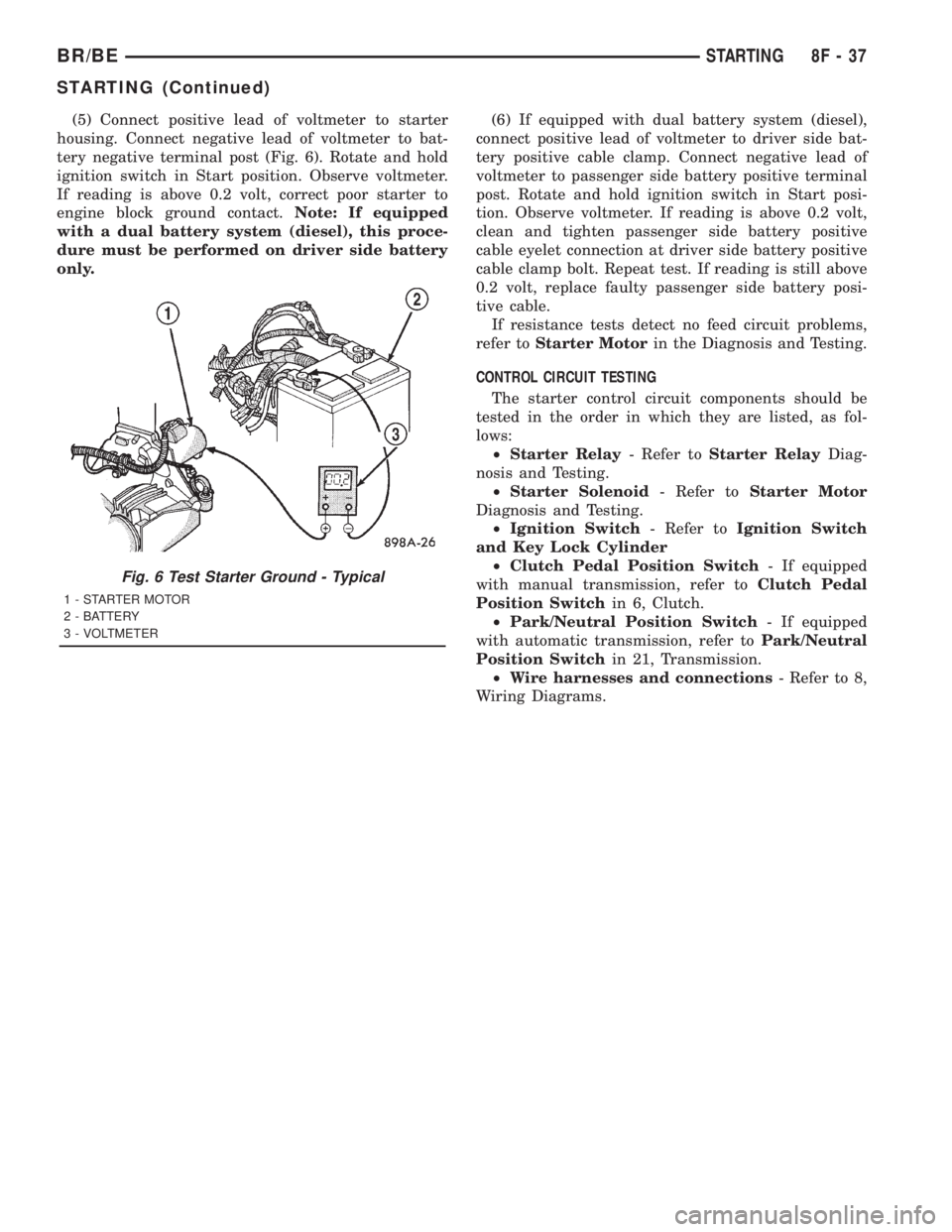
(5) Connect positive lead of voltmeter to starter
housing. Connect negative lead of voltmeter to bat-
tery negative terminal post (Fig. 6). Rotate and hold
ignition switch in Start position. Observe voltmeter.
If reading is above 0.2 volt, correct poor starter to
engine block ground contact.Note: If equipped
with a dual battery system (diesel), this proce-
dure must be performed on driver side battery
only.(6) If equipped with dual battery system (diesel),
connect positive lead of voltmeter to driver side bat-
tery positive cable clamp. Connect negative lead of
voltmeter to passenger side battery positive terminal
post. Rotate and hold ignition switch in Start posi-
tion. Observe voltmeter. If reading is above 0.2 volt,
clean and tighten passenger side battery positive
cable eyelet connection at driver side battery positive
cable clamp bolt. Repeat test. If reading is still above
0.2 volt, replace faulty passenger side battery posi-
tive cable.
If resistance tests detect no feed circuit problems,
refer toStarter Motorin the Diagnosis and Testing.
CONTROL CIRCUIT TESTING
The starter control circuit components should be
tested in the order in which they are listed, as fol-
lows:
²Starter Relay- Refer toStarter RelayDiag-
nosis and Testing.
²Starter Solenoid- Refer toStarter Motor
Diagnosis and Testing.
²Ignition Switch- Refer toIgnition Switch
and Key Lock Cylinder
²Clutch Pedal Position Switch- If equipped
with manual transmission, refer toClutch Pedal
Position Switchin 6, Clutch.
²Park/Neutral Position Switch- If equipped
with automatic transmission, refer toPark/Neutral
Position Switchin 21, Transmission.
²Wire harnesses and connections- Refer to 8,
Wiring Diagrams.
Fig. 6 Test Starter Ground - Typical
1 - STARTER MOTOR
2 - BATTERY
3 - VOLTMETER
BR/BESTARTING 8F - 37
STARTING (Continued)
Page 513 of 2889
5.9L DIESEL ENGINE
(1) If equipped, position aluminum spacer to rear
of starter.
(2) Position starter motor to engine.
(3) Support starter and loosely install three
mounting bolts.
(4) Tighten 3 bolts to 43.4 N´m (32 ft. lbs.).
(5) Position wiring eyelets to starter studs and
install nuts. Tighten small nut to 6.2 N´m (55 in.
lbs.). Tighten large nut to 13.6 N´m (120 in. lbs.).
(6) Install protective rubber boot over stud.
(7) Lower vehicle.
(8) Connect battery cables to both batteries.
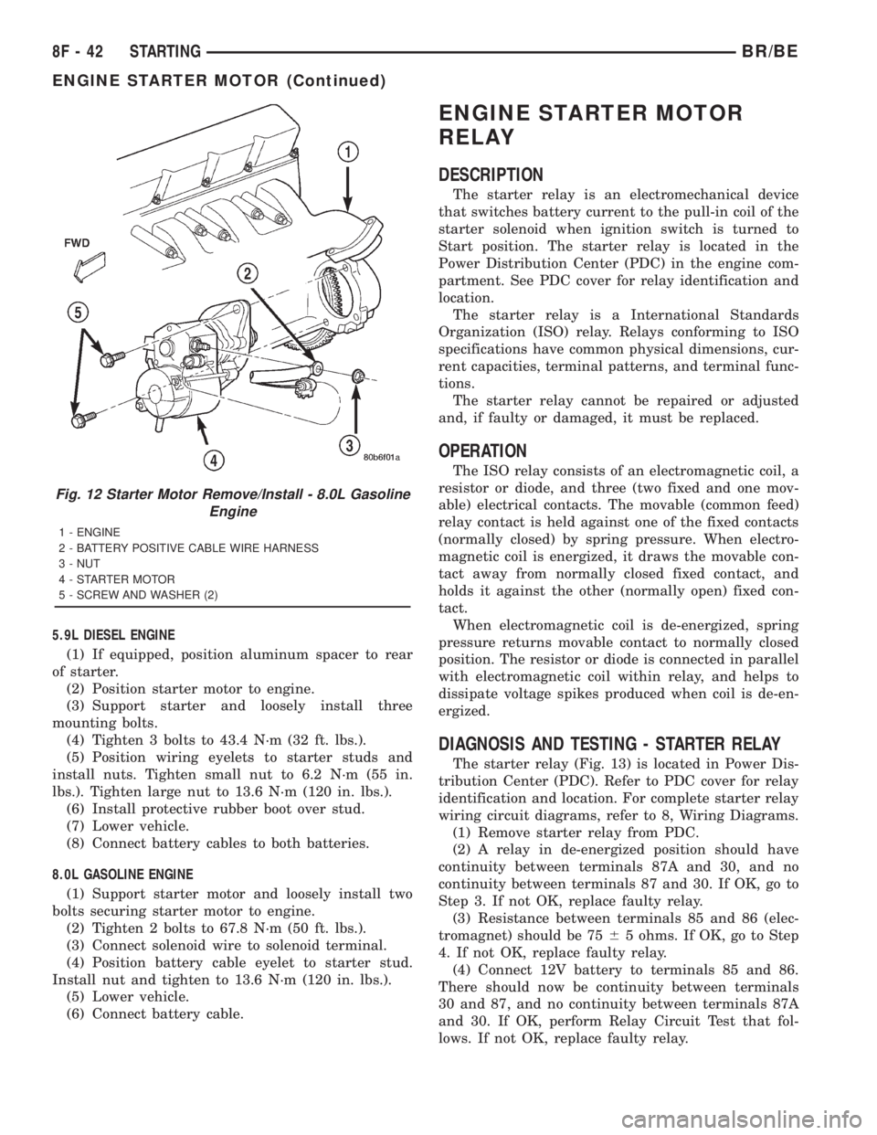
8.0L GASOLINE ENGINE
(1) Support starter motor and loosely install two
bolts securing starter motor to engine.
(2) Tighten 2 bolts to 67.8 N´m (50 ft. lbs.).
(3) Connect solenoid wire to solenoid terminal.
(4) Position battery cable eyelet to starter stud.
Install nut and tighten to 13.6 N´m (120 in. lbs.).
(5) Lower vehicle.
(6) Connect battery cable.
ENGINE STARTER MOTOR
RELAY
DESCRIPTION
The starter relay is an electromechanical device
that switches battery current to the pull-in coil of the
starter solenoid when ignition switch is turned to
Start position. The starter relay is located in the
Power Distribution Center (PDC) in the engine com-
partment. See PDC cover for relay identification and
location.
The starter relay is a International Standards
Organization (ISO) relay. Relays conforming to ISO
specifications have common physical dimensions, cur-
rent capacities, terminal patterns, and terminal func-
tions.
The starter relay cannot be repaired or adjusted
and, if faulty or damaged, it must be replaced.
OPERATION
The ISO relay consists of an electromagnetic coil, a
resistor or diode, and three (two fixed and one mov-
able) electrical contacts. The movable (common feed)
relay contact is held against one of the fixed contacts
(normally closed) by spring pressure. When electro-
magnetic coil is energized, it draws the movable con-
tact away from normally closed fixed contact, and
holds it against the other (normally open) fixed con-
tact.
When electromagnetic coil is de-energized, spring
pressure returns movable contact to normally closed
position. The resistor or diode is connected in parallel
with electromagnetic coil within relay, and helps to
dissipate voltage spikes produced when coil is de-en-
ergized.
DIAGNOSIS AND TESTING - STARTER RELAY
The starter relay (Fig. 13) is located in Power Dis-
tribution Center (PDC). Refer to PDC cover for relay
identification and location. For complete starter relay
wiring circuit diagrams, refer to 8, Wiring Diagrams.
(1) Remove starter relay from PDC.
(2) A relay in de-energized position should have
continuity between terminals 87A and 30, and no
continuity between terminals 87 and 30. If OK, go to
Step 3. If not OK, replace faulty relay.
(3) Resistance between terminals 85 and 86 (elec-
tromagnet) should be 7565 ohms. If OK, go to Step
4. If not OK, replace faulty relay.
(4) Connect 12V battery to terminals 85 and 86.
There should now be continuity between terminals
30 and 87, and no continuity between terminals 87A
and 30. If OK, perform Relay Circuit Test that fol-
lows. If not OK, replace faulty relay.
Fig. 12 Starter Motor Remove/Install - 8.0L Gasoline
Engine
1 - ENGINE
2 - BATTERY POSITIVE CABLE WIRE HARNESS
3 - NUT
4 - STARTER MOTOR
5 - SCREW AND WASHER (2)
8F - 42 STARTINGBR/BE
ENGINE STARTER MOTOR (Continued)
Page 518 of 2889
MIRROR SWITCH
DESCRIPTION
The heated mirror switch, the heated mirror sys-
tem indicator lamp, the heated mirror system solid
state electronic control logic and timer circuitry and
the heated mirror relay are all integral to the a/c
heater control, which is located between the instru-
ment cluster and the radio near the center of the
instrument cluster bezel on the instrument panel.
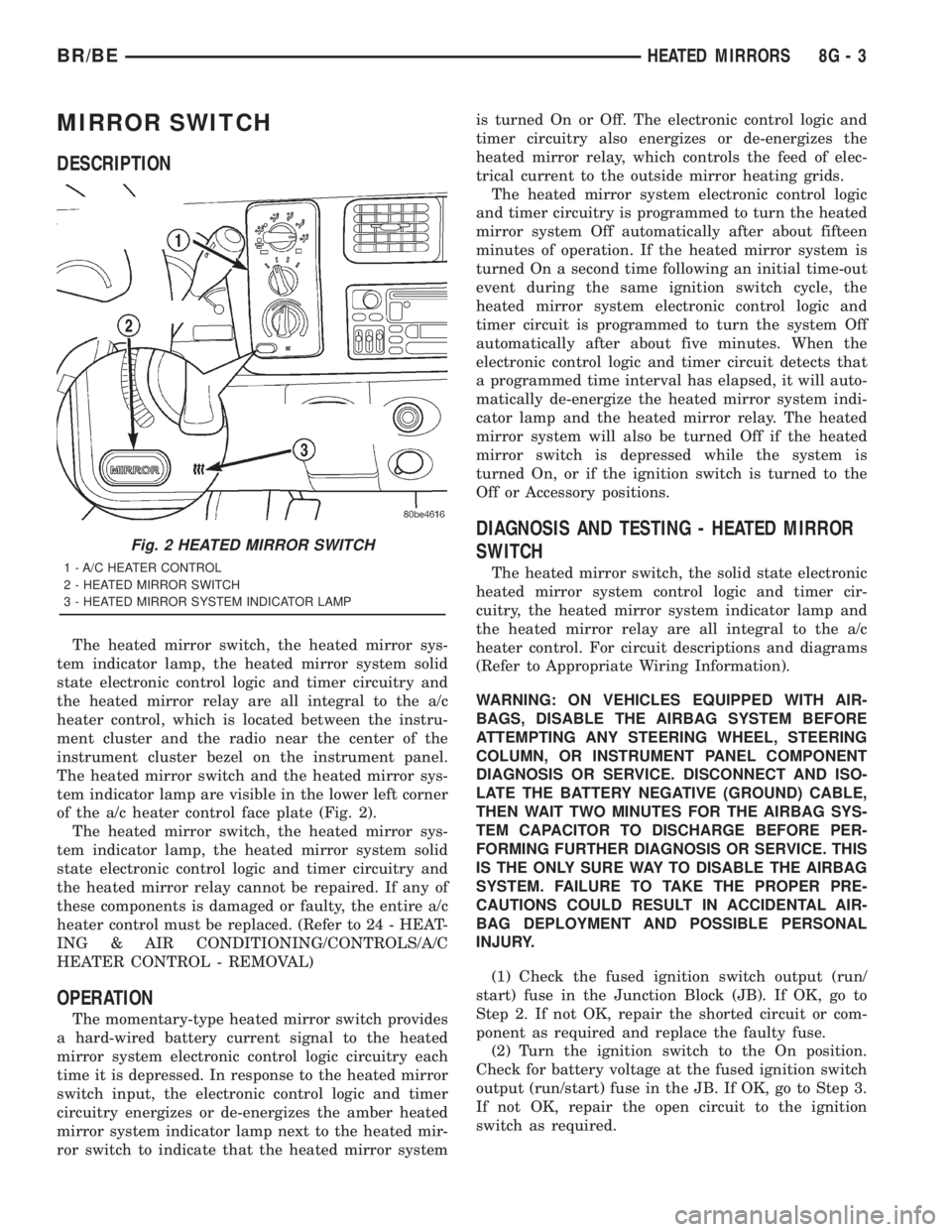
The heated mirror switch and the heated mirror sys-
tem indicator lamp are visible in the lower left corner
of the a/c heater control face plate (Fig. 2).
The heated mirror switch, the heated mirror sys-
tem indicator lamp, the heated mirror system solid
state electronic control logic and timer circuitry and
the heated mirror relay cannot be repaired. If any of
these components is damaged or faulty, the entire a/c
heater control must be replaced. (Refer to 24 - HEAT-
ING & AIR CONDITIONING/CONTROLS/A/C
HEATER CONTROL - REMOVAL)
OPERATION
The momentary-type heated mirror switch provides
a hard-wired battery current signal to the heated
mirror system electronic control logic circuitry each
time it is depressed. In response to the heated mirror
switch input, the electronic control logic and timer
circuitry energizes or de-energizes the amber heated
mirror system indicator lamp next to the heated mir-
ror switch to indicate that the heated mirror systemis turned On or Off. The electronic control logic and
timer circuitry also energizes or de-energizes the
heated mirror relay, which controls the feed of elec-
trical current to the outside mirror heating grids.
The heated mirror system electronic control logic
and timer circuitry is programmed to turn the heated
mirror system Off automatically after about fifteen
minutes of operation. If the heated mirror system is
turned On a second time following an initial time-out
event during the same ignition switch cycle, the
heated mirror system electronic control logic and
timer circuit is programmed to turn the system Off
automatically after about five minutes. When the
electronic control logic and timer circuit detects that
a programmed time interval has elapsed, it will auto-
matically de-energize the heated mirror system indi-
cator lamp and the heated mirror relay. The heated
mirror system will also be turned Off if the heated
mirror switch is depressed while the system is
turned On, or if the ignition switch is turned to the
Off or Accessory positions.
DIAGNOSIS AND TESTING - HEATED MIRROR
SWITCH
The heated mirror switch, the solid state electronic
heated mirror system control logic and timer cir-
cuitry, the heated mirror system indicator lamp and
the heated mirror relay are all integral to the a/c
heater control. For circuit descriptions and diagrams
(Refer to Appropriate Wiring Information).
WARNING: ON VEHICLES EQUIPPED WITH AIR-
BAGS, DISABLE THE AIRBAG SYSTEM BEFORE
ATTEMPTING ANY STEERING WHEEL, STEERING
COLUMN, OR INSTRUMENT PANEL COMPONENT
DIAGNOSIS OR SERVICE. DISCONNECT AND ISO-
LATE THE BATTERY NEGATIVE (GROUND) CABLE,
THEN WAIT TWO MINUTES FOR THE AIRBAG SYS-
TEM CAPACITOR TO DISCHARGE BEFORE PER-
FORMING FURTHER DIAGNOSIS OR SERVICE. THIS
IS THE ONLY SURE WAY TO DISABLE THE AIRBAG
SYSTEM. FAILURE TO TAKE THE PROPER PRE-
CAUTIONS COULD RESULT IN ACCIDENTAL AIR-
BAG DEPLOYMENT AND POSSIBLE PERSONAL
INJURY.
(1) Check the fused ignition switch output (run/
start) fuse in the Junction Block (JB). If OK, go to
Step 2. If not OK, repair the shorted circuit or com-
ponent as required and replace the faulty fuse.
(2) Turn the ignition switch to the On position.
Check for battery voltage at the fused ignition switch
output (run/start) fuse in the JB. If OK, go to Step 3.
If not OK, repair the open circuit to the ignition
switch as required.
Fig. 2 HEATED MIRROR SWITCH
1 - A/C HEATER CONTROL
2 - HEATED MIRROR SWITCH
3 - HEATED MIRROR SYSTEM INDICATOR LAMP
BR/BEHEATED MIRRORS 8G - 3
Page 519 of 2889
(3) Disconnect and isolate the battery negative
cable. Disconnect the 3-way instrument panel wire
harness connector for the heated mirror switch from
the heated mirror switch connector receptacle on the
back of the a/c heater control. Check for continuity
between the ground circuit cavity of the wire harness
connector and a good ground. There should be conti-
nuity. If OK, go to Step 4. If not OK, repair the open
ground circuit to ground as required.
(4) Reconnect the battery negative cable. Turn the
ignition switch to the On position. Check for battery
voltage at the fused ignition switch output (run/start)
circuit cavity of the 3-way instrument panel wire
harness connector for the heated mirror switch. If
OK, go to Step 5. If not OK, repair the open fused
ignition switch output (run/start) circuit to the fuse
in the JB as required.
(5) Turn the ignition switch to the Off position.
Disconnect and isolate the battery negative cable.
Reconnect the 3-way instrument panel wire harness
connector for the heated mirror switch to the heated
mirror switch connector receptacle on the back of the
a/c heater control. Reconnect the battery negative
cable. Turn the ignition switch to the On position.
Depress and release the heated mirror switch. The
amber heated mirror system indicator lamp next to
the heated mirror switch button should light. If OK,
go to Step 6. If not OK, replace the faulty a/c heater
control.
(6) Back probe the fused heated mirror relay out-
put circuit cavity of the 3-way instrument panel wire
harness connector for the heated mirror switch on
the back of the a/c heater control and check for volt-
age (battery voltage less the resistance in both out-
side mirror heating grids). If OK, (Refer to 8 -
ELECTRICAL/HEATED MIRRORS/HEATED MIR-
ROR GRID - DIAGNOSIS AND TESTING).
HEATED MIRROR GRID
DESCRIPTION
Vehicles equipped with the optional heated mirror
system have an electrically operated heating grid
located behind the mirror glass of each power oper-
ated outside rear view mirror. The outside mirror
heating grid consists of two thin laminations of plas-
tic that approximate the outer dimensions and shape
of the mirror glass. A single length of resistor wire
weaves in a back and forth pattern between, and is
held in place by the two thin laminations of plastic.
The two ends of the resistor wire terminate near the
inboard edge of the grid, where they are soldered to
the ground feed and battery current feed wires con-
tained in the power mirror wire harness. The heating
grid is then sandwiched between the back of themolded plastic mirror glass case and the mirror
glass, where it remains in direct contact with the
back of the mirror glass at all times.
The outside mirror heating grids cannot be
repaired and, if faulty or damaged, the entire outside
power mirror unit must be replaced. Refer to Power
Mirrors for the service procedures.
OPERATION
One end of the outside mirror heating grid resistor
wire is connected to a ground feed at all times
through a body ground screw located inside the left
rear corner of the truck cab. Battery current is
directed to the other end of the outside mirror heat-
ing grid resistor wire by the energized heated mirror
relay when the heated mirror switch is in the On
position. As electrical current passes through the
heating grid, the resistance of the wire in the heating
grid converts some of that electrical current into
heat. The heat produced by the heating grid is then
conducted through the back of the mirror glass to
help keep the glass clear of ice, snow or fog.
DIAGNOSIS AND TESTING - HEATED MIRROR
GRID
For circuit descriptions and diagrams (Refer to
Appropriate Wiring Information).
(1) Disconnect and isolate the battery negative
cable. Disconnect the door wire harness connector
from the power mirror wire harness connector at the
power mirror with the inoperative heating grid.
Check for continuity between the ground circuit cav-
ity in the door wire harness connector for the power
mirror and a good ground. If OK, go to Step 2. If not
OK, repair the open ground circuit to ground as
required.
(2) Reconnect the battery negative cable. Turn the
ignition switch to the On position. Turn on the
heated mirror system. Check for voltage (battery
voltage less the resistance in the outside mirror heat-
ing grid that is still connected) at the fused heated
mirror relay output circuit cavity in the door wire
harness connector for the power mirror. If OK, go to
Step 3. If not OK, repair the open fused heated mir-
ror relay output circuit to the heater and air condi-
tioner control unit as required.
(3) Check the outside mirror heating grid by test-
ing for continuity between the ground circuit and the
fused heated mirror relay output circuit cavities in
the power mirror wire harness connector. There
should be continuity. If not OK, replace the faulty
power mirror. If OK, check the resistance through
the outside mirror heating grid. The correct resis-
tance should be from 10 to 16 ohms when measured
at an ambient temperature of 21É C (70É F). If not
OK, replace the faulty power mirror.
8G - 4 HEATED MIRRORSBR/BE
MIRROR SWITCH (Continued)
Page 520 of 2889
HEATED SEAT SYSTEM
TABLE OF CONTENTS
page page
HEATED SEAT SYSTEM
DESCRIPTION............................5
OPERATION.............................6
DIAGNOSIS AND TESTING..................6
HEATED SEAT SYSTEM..................6
DRIVER SEAT HEATER SWITCH
DESCRIPTION............................7
OPERATION.............................7
DIAGNOSIS AND TESTING..................8
HEATED SEAT SWITCH...................8
REMOVAL...............................9
INSTALLATION............................9
HEATED SEAT ELEMENT
DESCRIPTION...........................10
OPERATION.............................10
DIAGNOSIS AND TESTING.................11HEATED SEAT ELEMENT & SENSOR.......11
HEATED SEAT RELAY
DESCRIPTION...........................11
OPERATION.............................12
DIAGNOSIS AND TESTING.................12
HEATED SEAT RELAY...................12
REMOVAL..............................13
INSTALLATION...........................13
PASSENGER SEAT HEATER SWITCH
DESCRIPTION...........................13
OPERATION.............................14
DIAGNOSIS AND TESTING.................14
HEATED SEAT SWITCH..................14
REMOVAL..............................15
INSTALLATION...........................16
HEATED SEAT SYSTEM
DESCRIPTION
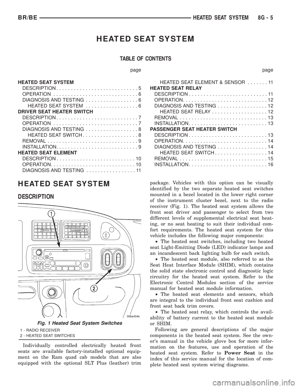
Individually controlled electrically heated front
seats are available factory-installed optional equip-
ment on the Ram quad cab models that are also
equipped with the optional SLT Plus (leather) trimpackage. Vehicles with this option can be visually
identified by the two separate heated seat switches
mounted in a bezel located in the lower right corner
of the instrument cluster bezel, next to the radio
receiver (Fig. 1). The heated seat system allows the
front seat driver and passenger to select from two
different levels of supplemental electrical seat heat-
ing, or no seat heating to suit their individual com-
fort requirements. The heated seat system for this
vehicle includes the following major components:
²The heated seat switches, including two heated
seat Light-Emitting Diode (LED) indicator lamps and
an incandescent back lighting bulb for each switch.
²The heated seat module, also referred to as the
Seat Heat Interface Module (SHIM), which contains
the solid state electronic control and diagnostic logic
circuitry for the heated seat system. Refer to the
Electronic Control Modules section of the service
manual for heated seat module information.
²The heated seat elements and sensors, which
are integral to the individual front seat cushion and
front seat back trim covers.
²The heated seat relay, which controls the avail-
ability of battery current to the heated seat module
or SHIM.
Following are general descriptions of the major
components in the heated seat system. See the own-
er's manual in the vehicle glove box for more infor-
mation on the features, use and operation of the
heated seat system. Refer toPower Seatin the
index of this service manual for the location of com-
plete heated seat system wiring diagrams.
Fig. 1 Heated Seat System Switches
1 - RADIO RECEIVER
2 - HEATED SEAT SWITCHES
BR/BEHEATED SEAT SYSTEM 8G - 5
Page 521 of 2889

OPERATION
The heated seat module receives fused battery cur-
rent through the energized heated seat relay in the
Junction Block (JB) only when the engine is running.
The heated seat switches receive battery current
through a fused ignition switch output (run) circuit
only when the ignition switch is in the On position.
The heated seat module shares a common ground cir-
cuit with each of the heated seat elements. The
heated seat elements will only operate when the sur-
face temperature of the seat cushion cover at the
heated seat sensors is below the designed tempera-
ture set points of the system.
The heated seat module will automatically turn off
the heated seat elements if it detects a short in the
heated seat element circuit or a heated seat sensor
value that is out of range. The heated seat system
will also be turned off automatically whenever the
ignition switch is turned to any position except On or
if the engine quits running. If the ignition switch is
turned to the Off position or if the engine quits run-
ning while a heated seat is turned ON, the heated
seat will remain Off after the engine is restarted
until a heated seat switch is depressed again.
The heated seat module monitors inputs from the
heated seat sensors and the heated seat switches. In
response to these inputs the heated seat module uses
its internal programming to control outputs to the
heated seat elements in both front seats and to con-
trol the heated seat LED indicator lamps located in
both of the heated seat switches. The heated seat
module is also programmed to provide a self-diagnos-
tic capability. When the module detects certain fail-
ures within the heated seat system, it will provide a
visual indication of the failure by flashing the indica-
tor lamps in the heated seat switches.
DIAGNOSIS & TESTING - HEATED SEAT
SYSTEM
SELF-DIAGNOSIS
The heated seat system is capable of performing
some self-diagnostics. The following table depicts the
various failure modes which will be reported to the
vehicle operator or technician by flashing the individ-
ual heated seat switch Light Emitting Diode (LED)
indicator lamps. See the Heated Seat System Self-Di-
agnosis table for the diagnostic routines. The driver
side heated seat switch indicator lamps will flash if a
failure occurs in the driver side heated seat, and the
passenger side heated seat switch indicator lamps
will flash for a passenger side heated seat failure. If
a monitored heated seat system failure occurs, the
switch indicator lamps will flash at a pulse rate of
about one-half second on, followed by about one-half
second off for a duration of about one minute afterthe switch for the faulty heated seat is depressed in
either the Low or High direction. This process will
repeat every time the faulty heated seat switch is
actuated until the problem has been corrected.
Heated Seat System Self-Diagnosis
Monitored FailureSwitch High
Indicator LampSwitch Low
Indicator Lamp
Heated Seat
Element ShortedFlashing Flashing
Heated Seat
Element OpenFlashing Off
Heated Seat
Sensor Value Out
of RangeOff Flashing
TESTING
Refer toPower Seatin the index of this service
manual for the location of complete heated seat sys-
tem wiring diagrams. Before testing the individual
components in the heated seat system, perform the
following preliminary checks:
WARNING: ON VEHICLES EQUIPPED WITH AIR-
BAGS, DISABLE THE AIRBAG SYSTEM BEFORE
ATTEMPTING ANY STEERING WHEEL, STEERING
COLUMN, OR INSTRUMENT PANEL COMPONENT
DIAGNOSIS OR SERVICE. DISCONNECT AND ISO-
LATE THE BATTERY NEGATIVE (GROUND) CABLE,
THEN WAIT TWO MINUTES FOR THE AIRBAG SYS-
TEM CAPACITOR TO DISCHARGE BEFORE PER-
FORMING FURTHER DIAGNOSIS OR SERVICE. THIS
IS THE ONLY SURE WAY TO DISABLE THE AIRBAG
SYSTEM. FAILURE TO TAKE THE PROPER PRE-
CAUTIONS COULD RESULT IN ACCIDENTAL AIR-
BAG DEPLOYMENT AND POSSIBLE PERSONAL
INJURY.
²If the heated seat switch back lighting and the
cluster illumination lamps do not illuminate with the
headlamps or park lamps turned On, refer toInstru-
ment Clusterin the index of this service manual for
the location of the proper cluster illumination lamps
diagnosis and testing procedures. If the heated seat
switch back lighting does not illuminate, but the
cluster illumination lamps do illuminate with the
headlamps or park lamps turned On, refer to
Heated Seat Switchin this section for the location
of the proper heated seat switch diagnosis and test-
ing procedure.
²If a single indicator lamp for one heated seat
switch does not operate and the heated seat elements
do heat, refer toHeated Seat Switchin this section
for the location of the proper heated seat switch diag-
nosis and testing procedure.
8G - 6 HEATED SEAT SYSTEMBR/BE
HEATED SEAT SYSTEM (Continued)
Page 523 of 2889
The indicator lamps in the heated seat switches
receive battery current through a fused ignition
switch output (run) circuit when the ignition switch
is in the On position. The ground side of each indi-
cator lamp is controlled by a separate (high or low/
driver or passenger) indicator lamp driver circuit by
the heated seat module. The heated seat module con-
trol of the switch indicator lamps also allows the
module to provide diagnostic feedback to the vehicle
operator to indicate monitored heated seat system
faults by flashing the indicator lamps on and off. One
side of the incandescent back lighting bulb in each
heated seat switch is connected to ground at all
times. The other side of the incandescent bulb is con-
nected to the fused panel lamps dimmer switch sig-
nal circuit. These bulbs are energized when the park
lamps or headlamps are turned on, and their illumi-
nation intensity is controlled by the panel lamps dim-
mer switch.
DIAGNOSIS & TESTING - HEATED SEAT
SWITCH
Refer toWiring Diagramsfor the location of com-
plete heated seat system wiring diagrams.
WARNING: ON VEHICLES EQUIPPED WITH AIR-
BAGS, DISABLE THE AIRBAG SYSTEM BEFORE
ATTEMPTING ANY STEERING WHEEL, STEERING
COLUMN, OR INSTRUMENT PANEL COMPONENT
DIAGNOSIS OR SERVICE. DISCONNECT AND ISO-
LATE THE BATTERY NEGATIVE (GROUND) CABLE,
THEN WAIT TWO MINUTES FOR THE AIRBAG SYS-
TEM CAPACITOR TO DISCHARGE BEFORE PER-
FORMING FURTHER DIAGNOSIS OR SERVICE. THIS
IS THE ONLY SURE WAY TO DISABLE THE AIRBAG
SYSTEM. FAILURE TO TAKE THE PROPER PRE-
CAUTIONS COULD RESULT IN ACCIDENTAL AIR-
BAG DEPLOYMENT AND POSSIBLE PERSONAL
INJURY.
(1) If the problem being diagnosed involves inoper-
ative heated seat switch back lighting and the cluster
illumination lamps operate, go to Step 2. If the prob-
lem being diagnosed involves inoperative heated seat
switch back lighting and the cluster illumination
lamps are also inoperative, refer toInstrument
Clusterin the index of this service manual for the
proper cluster illumination lamps diagnosis and test-
ing procedures. If the problem being diagnosed
involves inoperative heated seat switch indicator
lamps and the heated seat elements do not heat,
refer to Step 4. If the problem being diagnosed
involves inoperative heated seat switch indicator
lamps and the heated seat elements do heat, go to
Step 8. If the problem being diagnosed involves a
heated seat switch indicator lamp that remains illu-minated after the heated seat has been turned Off,
refer toHeated Seat Modulein Electronic Control
Modules for the location of the proper heated seat
module diagnosis and testing procedures. Also refer
to the Body Diagnostic Manual for additional diagno-
sis and testing procedures.
(2) Disconnect and isolate the battery negative
cable. Remove the heated seat switch and bezel unit
from the instrument panel. Disconnect the instru-
ment panel wire harness connector from the connec-
tor receptacle on the back of the heated seat switch
to be tested. Check for continuity between the ground
circuit cavity of the instrument panel wire harness
connector for the heated seat switch and a good
ground. There should be continuity. If OK, go to Step
3. If not OK, repair the open ground circuit to ground
as required.
(3) Reconnect the battery negative cable. Turn the
park lamps on with the headlamp switch. Rotate the
panel lamps dimmer thumbwheel on the headlamp
switch upward to just before the interior lamps
detent. Check for battery voltage at the fused panel
lamps dimmer switch signal circuit cavity of the
instrument panel wire harness connector for the
heated seat switch. If OK, replace the faulty heated
seat switch. If not OK, repair the open fused panel
lamps dimmer switch signal circuit to the fuse in the
Junction Block (JB) as required.
(4) Check the fused ignition switch output (run)
fuse in the Junction Block (JB). If OK, go to Step 5.
If not OK, repair the shorted circuit or component as
required and replace the faulty fuse.
(5) Turn the ignition switch to the On position.
Check for battery voltage at the fused ignition switch
output (run) fuse in the JB. If OK, go to Step 6. If
not OK, repair the open fused ignition switch output
(run) circuit to the ignition switch as required.
(6) Disconnect and isolate the battery negative
cable. Remove the heated seat switch and bezel unit
from the instrument panel. Disconnect the instru-
ment panel wire harness connector from the connec-
tor receptacle on the back of the heated seat switch
to be tested. Reconnect the battery negative cable.
Turn the ignition switch to the On position. Check
for battery voltage at the fused ignition switch out-
put (run) circuit cavity of the instrument panel wire
harness connector for the heated seat switch. If OK,
go to Step 7. If not OK, repair the open fused ignition
switch output (run) circuit to the JB fuse as required.
(7) Check the continuity and resistance values of
the heated seat switch in the Neutral, Low and High
positions as shown in the Heated Seat Switch Conti-
nuity chart (Fig. 3). If OK, refer toHeated Seat
Modulein Electronic Control Modules for the loca-
tion of the proper heated seat module diagnosis and
testing procedures. Also refer to the Body Diagnostic
8G - 8 HEATED SEAT SYSTEMBR/BE
DRIVER SEAT HEATER SWITCH (Continued)