2001 DODGE RAM lug pattern
[x] Cancel search: lug patternPage 1273 of 2889
(1) Perform the Fuel Pressure Release Procedure
(Refer to 14 - FUEL SYSTEM/FUEL DELIVERY -
STANDARD PROCEDURE).
(2) Disconnect the negative cable(s) from the bat-
tery.
(3) Inspect air cleaner, induction system, and
intake manifold to ensure system is dry and clear of
foreign material.
(4) Place a shop towel around the spark plugs to
catch any fluid that may possibly be under pressure
in the cylinder head. Remove the spark plugs.
(5) With all spark plugs removed, rotate the crank-
shaft using a breaker bar and socket.
(6) Identify the fluid in the cylinders (coolant, fuel,
oil, etc.).
(7) Be sure all fluid has been removed from the
cylinders.
(8) Repair engine or components as necessary to
prevent this problem from occurring again.
(9) Squirt a small amount of engine oil into the
cylinders to lubricate the walls. This will prevent
damage on restart.
(10) Install new spark plugs. Tighten the spark
plugs to 41 N´m (30 ft. lbs.) torque.
(11) Drain engine oil. Remove and discard the oil
filter.
(12) Install the drain plug. Tighten the plug to 34
N´m (25 ft. lbs.) torque.
(13) Install a new oil filter.
(14) Fill engine crankcase with the specified
amount and grade of oil. (Refer to LUBRICATION &
MAINTENANCE - SPECIFICATIONS).
(15) Connect the negative cable(s) to the battery.
(16) Start the engine and check for any leaks.
STANDARD PROCEDUREÐCYLINDER BORE
HONING
Before honing, stuff plenty of clean shop towels
under the bores and over the crankshaft to keep
abrasive materials from entering the crankshaft
area.
(1) Used carefully, the Cylinder Bore Sizing Hone
C-823, equipped with 220 grit stones, is the best tool
for this job. In addition to deglazing, it will reduce
taper and out-of-round, as well as removing light
scuffing, scoring and scratches. Usually, a few strokes
will clean up a bore and maintain the required lim-
its.
CAUTION: DO NOT use rigid type hones to remove
cylinder wall glaze.
(2) Deglazing of the cylinder walls may be done if
the cylinder bore is straight and round. Use a cylin-
der surfacing hone, Honing Tool C-3501, equipped
with 280 grit stones (C-3501-3810). about 20-60strokes, depending on the bore condition, will be suf-
ficient to provide a satisfactory surface. Using honing
oil C-3501-3880, or a light honing oil, available from
major oil distributors.
CAUTION: DO NOT use engine or transmission oil,
mineral spirits, or kerosene.
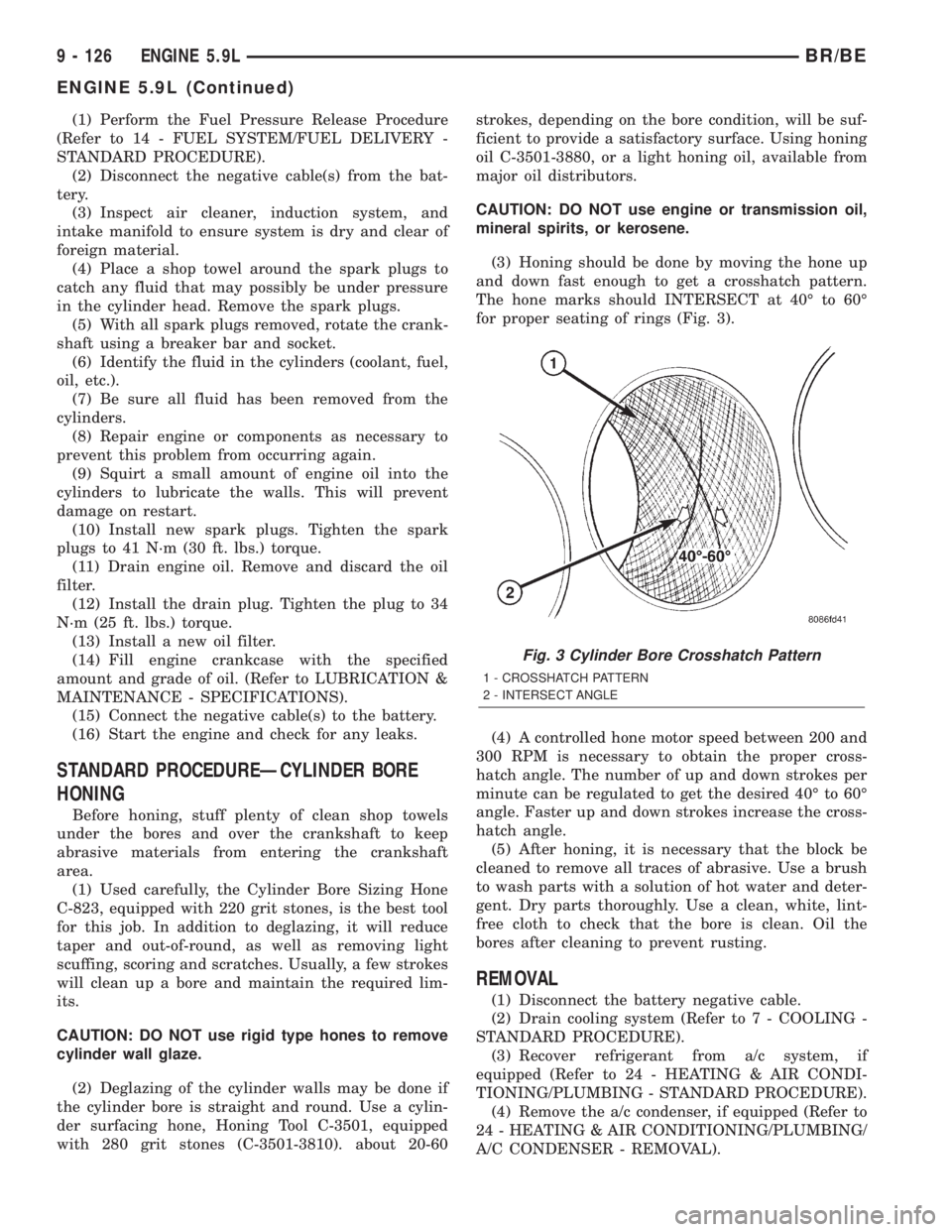
(3) Honing should be done by moving the hone up
and down fast enough to get a crosshatch pattern.
The hone marks should INTERSECT at 40É to 60É
for proper seating of rings (Fig. 3).
(4) A controlled hone motor speed between 200 and
300 RPM is necessary to obtain the proper cross-
hatch angle. The number of up and down strokes per
minute can be regulated to get the desired 40É to 60É
angle. Faster up and down strokes increase the cross-
hatch angle.
(5) After honing, it is necessary that the block be
cleaned to remove all traces of abrasive. Use a brush
to wash parts with a solution of hot water and deter-
gent. Dry parts thoroughly. Use a clean, white, lint-
free cloth to check that the bore is clean. Oil the
bores after cleaning to prevent rusting.
REMOVAL
(1) Disconnect the battery negative cable.
(2) Drain cooling system (Refer to 7 - COOLING -
STANDARD PROCEDURE).
(3) Recover refrigerant from a/c system, if
equipped (Refer to 24 - HEATING & AIR CONDI-
TIONING/PLUMBING - STANDARD PROCEDURE).
(4) Remove the a/c condenser, if equipped (Refer to
24 - HEATING & AIR CONDITIONING/PLUMBING/
A/C CONDENSER - REMOVAL).
Fig. 3 Cylinder Bore Crosshatch Pattern
1 - CROSSHATCH PATTERN
2 - INTERSECT ANGLE
9 - 126 ENGINE 5.9LBR/BE
ENGINE 5.9L (Continued)
Page 1426 of 2889
(3) Remove the oil pan drain plug and drain the
engine oil. Re-install plug and torque to 60 N´m (44
ft. lbs.) torque.
(4) Remove transmission and transfer case (if
equipped) from vehicle.
(5) Remove flywheel or torque converter drive
plate.
(6) Disconnect starter cables from starter motor.
(7) Remove starter motor (Refer to 8 - ELECTRI-
CAL/STARTING/STARTER MOTOR - REMOVAL)
and transmission adapter plate assembly.
(8) Disconnect cables from starter motor.
(9) Remove the eight flywheel housing to block
bolts and remove housing and starter motor as an
assembly.
(10) Remove oil pan bolts, break the pan to block
seal, and lower pan slightly and remove oil suction
tube fasteners.
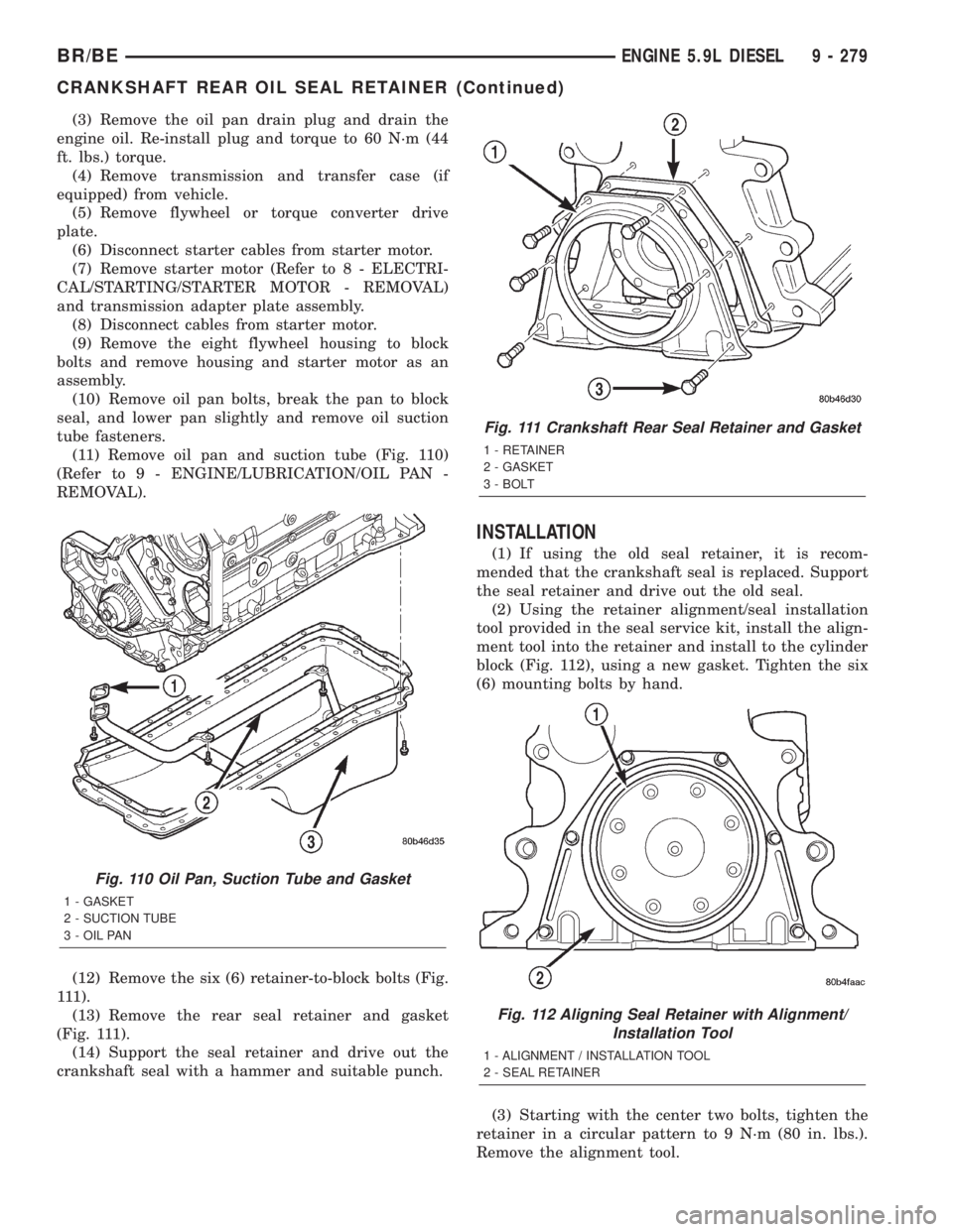
(11) Remove oil pan and suction tube (Fig. 110)
(Refer to 9 - ENGINE/LUBRICATION/OIL PAN -
REMOVAL).
(12) Remove the six (6) retainer-to-block bolts (Fig.
111).
(13) Remove the rear seal retainer and gasket
(Fig. 111).
(14) Support the seal retainer and drive out the
crankshaft seal with a hammer and suitable punch.
INSTALLATION
(1) If using the old seal retainer, it is recom-
mended that the crankshaft seal is replaced. Support
the seal retainer and drive out the old seal.
(2) Using the retainer alignment/seal installation
tool provided in the seal service kit, install the align-
ment tool into the retainer and install to the cylinder
block (Fig. 112), using a new gasket. Tighten the six
(6) mounting bolts by hand.
(3) Starting with the center two bolts, tighten the
retainer in a circular pattern to 9 N´m (80 in. lbs.).
Remove the alignment tool.
Fig. 110 Oil Pan, Suction Tube and Gasket
1 - GASKET
2 - SUCTION TUBE
3 - OIL PAN
Fig. 111 Crankshaft Rear Seal Retainer and Gasket
1 - RETAINER
2 - GASKET
3 - BOLT
Fig. 112 Aligning Seal Retainer with Alignment/
Installation Tool
1 - ALIGNMENT / INSTALLATION TOOL
2 - SEAL RETAINER
BR/BEENGINE 5.9L DIESEL 9 - 279
CRANKSHAFT REAR OIL SEAL RETAINER (Continued)
Page 1583 of 2889
(3) Once injector has been found to be malfunc-
tioning, remove it from engine and test it. Refer to
Fuel Injector Removal/Installation.
WARNING: FUEL INJECTOR TESTERS CAN
DEVELOP EXTREMELY HIGH PRESSURES. FUEL
UNDER THIS AMOUNT OF PRESSURE CAN PENE-
TRATE SKIN AND CAUSE PERSONAL INJURY.
WEAR SAFETY GOGGLES AND ADEQUATE PRO-TECTIVE CLOTHING. AVOID CONTACT WITH FUEL
SPRAY WHEN OPERATING INJECTOR TESTOR.
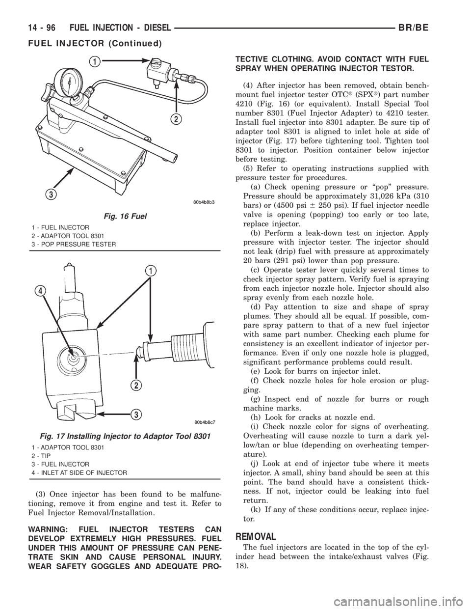
(4) After injector has been removed, obtain bench-
mount fuel injector tester OTCt(SPXt) part number
4210 (Fig. 16) (or equivalent). Install Special Tool
number 8301 (Fuel Injector Adapter) to 4210 tester.
Install fuel injector into 8301 adapter. Be sure tip of
adapter tool 8301 is aligned to inlet hole at side of
injector (Fig. 17) before tightening tool. Tighten tool
8301 to injector. Position container below injector
before testing.
(5) Refer to operating instructions supplied with
pressure tester for procedures.
(a) Check opening pressure or ªpopº pressure.
Pressure should be approximately 31,026 kPa (310
bars) or (4500 psi6250 psi). If fuel injector needle
valve is opening (popping) too early or too late,
replace injector.
(b) Perform a leak-down test on injector. Apply
pressure with injector tester. The injector should
not leak (drip) fuel with pressure at approximately
20 bars (291 psi) lower than pop pressure.
(c) Operate tester lever quickly several times to
check injector spray pattern. Verify fuel is spraying
from each injector nozzle hole. Injector should also
spray evenly from each nozzle hole.
(d) Pay attention to size and shape of spray
plumes. They should all be equal. If possible, com-
pare spray pattern to that of a new fuel injector
with same part number. Checking each plume for
consistency is an excellent indicator of injector per-
formance. Even if only one nozzle hole is plugged,
significant performance problems could result.
(e) Look for burrs on injector inlet.
(f) Check nozzle holes for hole erosion or plug-
ging.
(g) Inspect end of nozzle for burrs or rough
machine marks.
(h) Look for cracks at nozzle end.
(i) Check nozzle color for signs of overheating.
Overheating will cause nozzle to turn a dark yel-
low/tan or blue (depending on overheating temper-
ature).
(j) Look at end of injector tube where it meets
injector. A small, shiny band should be seen at this
point. The band should have a consistent thick-
ness. If not, injector could be leaking into fuel
return.
(k) If any of these conditions occur, replace injec-
tor.
REMOVAL
The fuel injectors are located in the top of the cyl-
inder head between the intake/exhaust valves (Fig.
18).
Fig. 16 Fuel
1 - FUEL INJECTOR
2 - ADAPTOR TOOL 8301
3 - POP PRESSURE TESTER
Fig. 17 Installing Injector to Adaptor Tool 8301
1 - ADAPTOR TOOL 8301
2 - TIP
3 - FUEL INJECTOR
4 - INLET AT SIDE OF INJECTOR
14 - 96 FUEL INJECTION - DIESELBR/BE
FUEL INJECTOR (Continued)
Page 1869 of 2889
(d) Push overdrive piston into position in
retainer.
(e) Verify that the locating lugs entered the lug
bores in the retainer.
(6) Install intermediate shaft spacer on intermedi-
ate shaft.
(7) Install overdrive piston thrust plate on over-
drive piston.
(8) Install overdrive piston thrust bearing on over-
drive piston.
(9) Install transmission speed sensor and O-ring
seal in overdrive case (Fig. 119).
INSTALLATION
(1) Be sure overdrive unit Alignment Tool 6227-2
is fully seated before moving unit. If tool is not
seated and gear splines rotate out of alignment, over-
drive unit will have to be disassembled in order to
realign splines.
(2) If overdrive piston retainer was not removed
during service and original case gasket is no longer
reusable, prepare new gasket by trimming it.
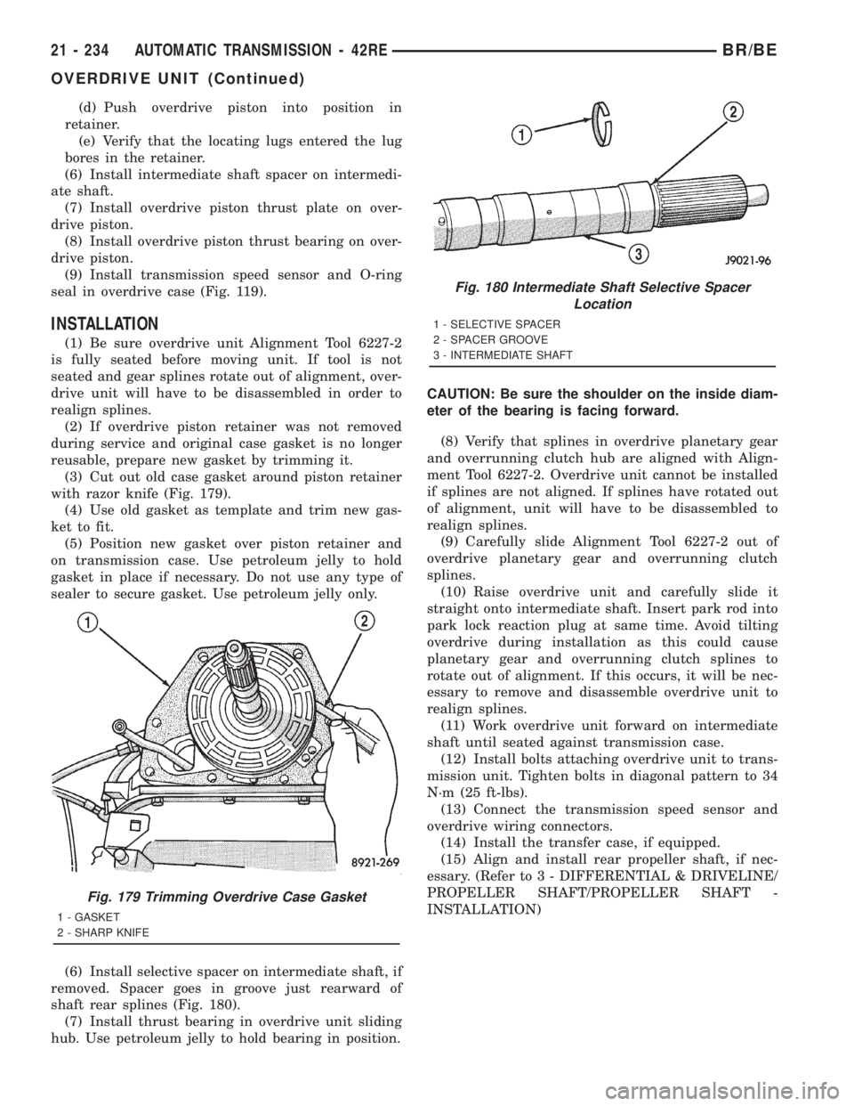
(3) Cut out old case gasket around piston retainer
with razor knife (Fig. 179).
(4) Use old gasket as template and trim new gas-
ket to fit.
(5) Position new gasket over piston retainer and
on transmission case. Use petroleum jelly to hold
gasket in place if necessary. Do not use any type of
sealer to secure gasket. Use petroleum jelly only.
(6) Install selective spacer on intermediate shaft, if
removed. Spacer goes in groove just rearward of
shaft rear splines (Fig. 180).
(7) Install thrust bearing in overdrive unit sliding
hub. Use petroleum jelly to hold bearing in position.CAUTION: Be sure the shoulder on the inside diam-
eter of the bearing is facing forward.
(8) Verify that splines in overdrive planetary gear
and overrunning clutch hub are aligned with Align-
ment Tool 6227-2. Overdrive unit cannot be installed
if splines are not aligned. If splines have rotated out
of alignment, unit will have to be disassembled to
realign splines.
(9) Carefully slide Alignment Tool 6227-2 out of
overdrive planetary gear and overrunning clutch
splines.
(10) Raise overdrive unit and carefully slide it
straight onto intermediate shaft. Insert park rod into
park lock reaction plug at same time. Avoid tilting
overdrive during installation as this could cause
planetary gear and overrunning clutch splines to
rotate out of alignment. If this occurs, it will be nec-
essary to remove and disassemble overdrive unit to
realign splines.
(11) Work overdrive unit forward on intermediate
shaft until seated against transmission case.
(12) Install bolts attaching overdrive unit to trans-
mission unit. Tighten bolts in diagonal pattern to 34
N´m (25 ft-lbs).
(13) Connect the transmission speed sensor and
overdrive wiring connectors.
(14) Install the transfer case, if equipped.
(15) Align and install rear propeller shaft, if nec-
essary. (Refer to 3 - DIFFERENTIAL & DRIVELINE/
PROPELLER SHAFT/PROPELLER SHAFT -
INSTALLATION)
Fig. 179 Trimming Overdrive Case Gasket
1 - GASKET
2 - SHARP KNIFE
Fig. 180 Intermediate Shaft Selective Spacer
Location
1 - SELECTIVE SPACER
2 - SPACER GROOVE
3 - INTERMEDIATE SHAFT
21 - 234 AUTOMATIC TRANSMISSION - 42REBR/BE
OVERDRIVE UNIT (Continued)
Page 2040 of 2889
(7) Install thrust bearing in overdrive unit sliding
hub. Use petroleum jelly to hold bearing in position.
CAUTION: Be sure the shoulder on the inside diam-
eter of the bearing is facing forward.
(8) Verify that splines in overdrive planetary gear
and overrunning clutch hub are aligned with Align-
ment Tool 6227-2. Overdrive unit cannot be installed
if splines are not aligned. If splines have rotated out
of alignment, unit will have to be disassembled to
realign splines.
(9) Carefully slide Alignment Tool 6227-2 out of
overdrive planetary gear and overrunning clutch
splines.
(10) Raise overdrive unit and carefully slide it
straight onto intermediate shaft. Insert park rod into
park lock reaction plug at same time. Avoid tilting
overdrive during installation as this could cause
planetary gear and overrunning clutch splines to
rotate out of alignment. If this occurs, it will be nec-
essary to remove and disassemble overdrive unit to
realign splines.
(11) Work overdrive unit forward on intermediate
shaft until seated against transmission case.
(12) Install bolts attaching overdrive unit to trans-
mission unit. Tighten bolts in diagonal pattern to 34
N´m (25 ft-lbs).
(13) Connect the transmission speed sensor and
overdrive wiring connectors.
(14) Install the transfer case, if equipped.
(15) Align and install rear propeller shaft, if nec-
essary. (Refer to 3 - DIFFERENTIAL & DRIVELINE/
PROPELLER SHAFT/PROPELLER SHAFT -
INSTALLATION)
OVERRUNNING CLUTCH
CAM/OVERDRIVE PISTON
RETAINER
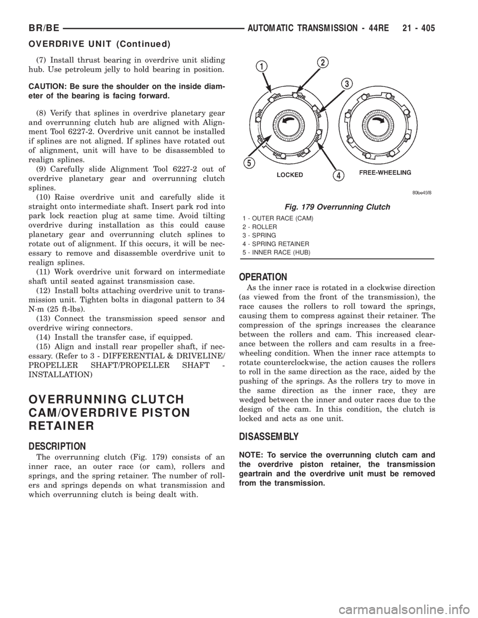
DESCRIPTION
The overrunning clutch (Fig. 179) consists of an
inner race, an outer race (or cam), rollers and
springs, and the spring retainer. The number of roll-
ers and springs depends on what transmission and
which overrunning clutch is being dealt with.
OPERATION
As the inner race is rotated in a clockwise direction
(as viewed from the front of the transmission), the
race causes the rollers to roll toward the springs,
causing them to compress against their retainer. The
compression of the springs increases the clearance
between the rollers and cam. This increased clear-
ance between the rollers and cam results in a free-
wheeling condition. When the inner race attempts to
rotate counterclockwise, the action causes the rollers
to roll in the same direction as the race, aided by the
pushing of the springs. As the rollers try to move in
the same direction as the inner race, they are
wedged between the inner and outer races due to the
design of the cam. In this condition, the clutch is
locked and acts as one unit.
DISASSEMBLY
NOTE: To service the overrunning clutch cam and
the overdrive piston retainer, the transmission
geartrain and the overdrive unit must be removed
from the transmission.
Fig. 179 Overrunning Clutch
1 - OUTER RACE (CAM)
2 - ROLLER
3 - SPRING
4 - SPRING RETAINER
5 - INNER RACE (HUB)
BR/BEAUTOMATIC TRANSMISSION - 44RE 21 - 405
OVERDRIVE UNIT (Continued)
Page 2107 of 2889
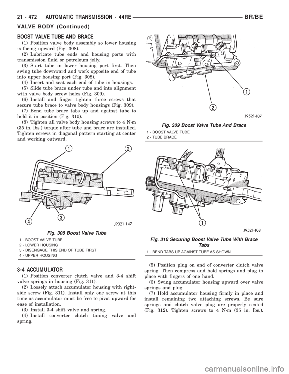
BOOST VALVE TUBE AND BRACE
(1) Position valve body assembly so lower housing
is facing upward (Fig. 308).
(2) Lubricate tube ends and housing ports with
transmission fluid or petroleum jelly.
(3) Start tube in lower housing port first. Then
swing tube downward and work opposite end of tube
into upper housing port (Fig. 308).
(4) Insert and seat each end of tube in housings.
(5) Slide tube brace under tube and into alignment
with valve body screw holes (Fig. 309).
(6) Install and finger tighten three screws that
secure tube brace to valve body housings (Fig. 309).
(7) Bend tube brace tabs up and against tube to
hold it in position (Fig. 310).
(8) Tighten all valve body housing screws to 4 N´m
(35 in. lbs.) torque after tube and brace are installed.
Tighten screws in diagonal pattern starting at center
and working outward.
3-4 ACCUMULATOR
(1) Position converter clutch valve and 3-4 shift
valve springs in housing (Fig. 311).
(2) Loosely attach accumulator housing with right-
side screw (Fig. 311). Install only one screw at this
time as accumulator must be free to pivot upward for
ease of installation.
(3) Install 3-4 shift valve and spring.
(4) Install converter clutch timing valve and
spring.(5) Position plug on end of converter clutch valve
spring. Then compress and hold springs and plug in
place with fingers of one hand.
(6) Swing accumulator housing upward over valve
springs and plug.
(7) Hold accumulator housing firmly in place and
install remaining two attaching screws. Be sure
springs and clutch valve plug are properly seated
(Fig. 312). Tighten screws to 4 N´m (35 in. lbs.).
Fig. 308 Boost Valve Tube
1 - BOOST VALVE TUBE
2 - LOWER HOUSING
3 - DISENGAGE THIS END OF TUBE FIRST
4 - UPPER HOUSING
Fig. 309 Boost Valve Tube And Brace
1 - BOOST VALVE TUBE
2 - TUBE BRACE
Fig. 310 Securing Boost Valve Tube With Brace
Tabs
1 - BEND TABS UP AGAINST TUBE AS SHOWN
21 - 472 AUTOMATIC TRANSMISSION - 44REBR/BE
VALVE BODY (Continued)
Page 2213 of 2889
seated and gear splines rotate out of alignment, over-
drive unit will have to be disassembled in order to
realign splines.
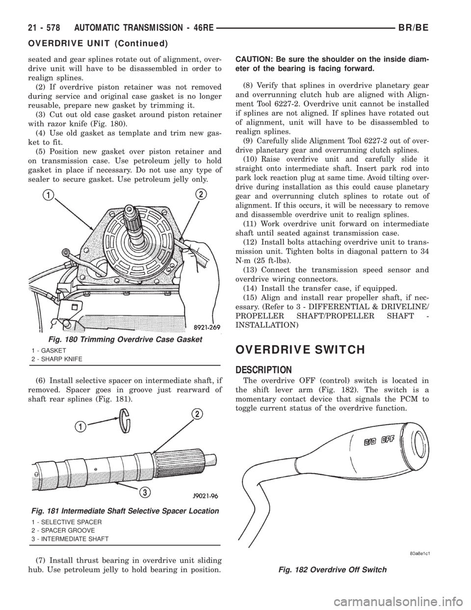
(2) If overdrive piston retainer was not removed
during service and original case gasket is no longer
reusable, prepare new gasket by trimming it.
(3) Cut out old case gasket around piston retainer
with razor knife (Fig. 180).
(4) Use old gasket as template and trim new gas-
ket to fit.
(5) Position new gasket over piston retainer and
on transmission case. Use petroleum jelly to hold
gasket in place if necessary. Do not use any type of
sealer to secure gasket. Use petroleum jelly only.
(6) Install selective spacer on intermediate shaft, if
removed. Spacer goes in groove just rearward of
shaft rear splines (Fig. 181).
(7) Install thrust bearing in overdrive unit sliding
hub. Use petroleum jelly to hold bearing in position.CAUTION: Be sure the shoulder on the inside diam-
eter of the bearing is facing forward.
(8) Verify that splines in overdrive planetary gear
and overrunning clutch hub are aligned with Align-
ment Tool 6227-2. Overdrive unit cannot be installed
if splines are not aligned. If splines have rotated out
of alignment, unit will have to be disassembled to
realign splines.
(9)
Carefully slide Alignment Tool 6227-2 out of over-
drive planetary gear and overrunning clutch splines.
(10)Raise overdrive unit and carefully slide it
straight onto intermediate shaft. Insert park rod into
park lock reaction plug at same time. Avoid tilting over-
drive during installation as this could cause planetary
gear and overrunning clutch splines to rotate out of
alignment. If this occurs, it will be necessary to remove
and disassemble overdrive unit to realign splines.
(11) Work overdrive unit forward on intermediate
shaft until seated against transmission case.
(12) Install bolts attaching overdrive unit to trans-
mission unit. Tighten bolts in diagonal pattern to 34
N´m (25 ft-lbs).
(13) Connect the transmission speed sensor and
overdrive wiring connectors.
(14) Install the transfer case, if equipped.
(15) Align and install rear propeller shaft, if nec-
essary. (Refer to 3 - DIFFERENTIAL & DRIVELINE/
PROPELLER SHAFT/PROPELLER SHAFT -
INSTALLATION)
OVERDRIVE SWITCH
DESCRIPTION
The overdrive OFF (control) switch is located in
the shift lever arm (Fig. 182). The switch is a
momentary contact device that signals the PCM to
toggle current status of the overdrive function.
Fig. 180 Trimming Overdrive Case Gasket
1 - GASKET
2 - SHARP KNIFE
Fig. 181 Intermediate Shaft Selective Spacer Location
1 - SELECTIVE SPACER
2 - SPACER GROOVE
3 - INTERMEDIATE SHAFT
Fig. 182 Overdrive Off Switch
21 - 578 AUTOMATIC TRANSMISSION - 46REBR/BE
OVERDRIVE UNIT (Continued)
Page 2386 of 2889
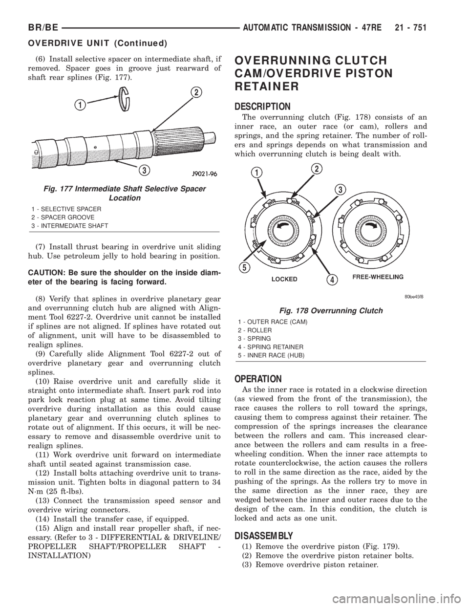
(6) Install selective spacer on intermediate shaft, if
removed. Spacer goes in groove just rearward of
shaft rear splines (Fig. 177).
(7) Install thrust bearing in overdrive unit sliding
hub. Use petroleum jelly to hold bearing in position.
CAUTION: Be sure the shoulder on the inside diam-
eter of the bearing is facing forward.
(8) Verify that splines in overdrive planetary gear
and overrunning clutch hub are aligned with Align-
ment Tool 6227-2. Overdrive unit cannot be installed
if splines are not aligned. If splines have rotated out
of alignment, unit will have to be disassembled to
realign splines.
(9) Carefully slide Alignment Tool 6227-2 out of
overdrive planetary gear and overrunning clutch
splines.
(10) Raise overdrive unit and carefully slide it
straight onto intermediate shaft. Insert park rod into
park lock reaction plug at same time. Avoid tilting
overdrive during installation as this could cause
planetary gear and overrunning clutch splines to
rotate out of alignment. If this occurs, it will be nec-
essary to remove and disassemble overdrive unit to
realign splines.
(11) Work overdrive unit forward on intermediate
shaft until seated against transmission case.
(12) Install bolts attaching overdrive unit to trans-
mission unit. Tighten bolts in diagonal pattern to 34
N´m (25 ft-lbs).
(13) Connect the transmission speed sensor and
overdrive wiring connectors.
(14) Install the transfer case, if equipped.
(15) Align and install rear propeller shaft, if nec-
essary. (Refer to 3 - DIFFERENTIAL & DRIVELINE/
PROPELLER SHAFT/PROPELLER SHAFT -
INSTALLATION)OVERRUNNING CLUTCH
CAM/OVERDRIVE PISTON
RETAINER
DESCRIPTION
The overrunning clutch (Fig. 178) consists of an
inner race, an outer race (or cam), rollers and
springs, and the spring retainer. The number of roll-
ers and springs depends on what transmission and
which overrunning clutch is being dealt with.
OPERATION
As the inner race is rotated in a clockwise direction
(as viewed from the front of the transmission), the
race causes the rollers to roll toward the springs,
causing them to compress against their retainer. The
compression of the springs increases the clearance
between the rollers and cam. This increased clear-
ance between the rollers and cam results in a free-
wheeling condition. When the inner race attempts to
rotate counterclockwise, the action causes the rollers
to roll in the same direction as the race, aided by the
pushing of the springs. As the rollers try to move in
the same direction as the inner race, they are
wedged between the inner and outer races due to the
design of the cam. In this condition, the clutch is
locked and acts as one unit.
DISASSEMBLY
(1) Remove the overdrive piston (Fig. 179).
(2) Remove the overdrive piston retainer bolts.
(3) Remove overdrive piston retainer.
Fig. 177 Intermediate Shaft Selective Spacer
Location
1 - SELECTIVE SPACER
2 - SPACER GROOVE
3 - INTERMEDIATE SHAFT
Fig. 178 Overrunning Clutch
1 - OUTER RACE (CAM)
2 - ROLLER
3 - SPRING
4 - SPRING RETAINER
5 - INNER RACE (HUB)
BR/BEAUTOMATIC TRANSMISSION - 47RE 21 - 751
OVERDRIVE UNIT (Continued)