2001 DODGE RAM front brakes
[x] Cancel search: front brakesPage 59 of 2889

SPECIAL TOOLS
LINK/COIL SUSPENSION
HUB / BEARING
REMOVAL - 2500/3500
(1) Raise and support the vehicle.
(2) Remove the wheel and tire assembly.
(3) Remove the hub extension mounting nuts and
remove the extension from the rotor if equipped (Fig.
2).(4) Remove the brake caliper, (Refer to 5 -
BRAKES/HYDRAULIC/MECHANICAL/DISC
BRAKE CALIPERS - REMOVAL).
(5) Remove the cotter pin and the hub nut from
the axle shaft (Fig. 3).
(6) Disconnect the ABS wheel speed sensor wire
from under the hood. Remove the sensor wire from
the frame and steering knuckle if equipped.
(7) Back off the hub/bearing mounting bolts 1/4
inch each (Fig. 4). Then tap the bolts with a hammer
to loosen the hub/bearing from the steering knuckle.
(8) Remove the hub/bearing mounting bolts and
remove the hub/bearing.
(9) Remove the rotor assembly (Fig. 5), brake
shield and spacer from the steering knuckle.
(10) Press out the wheel studs/hub extension studs
and separate the rotor from the hub (Fig. 6).
Puller C-3894±A
Remover, Wheel Stud C-4150A
Fig. 2 Hub Extension
1 - HUB EXTENSION
2 - HUB
Fig. 3 Hub Nut Cotter Pin
1 - HUB NUT
2 - COTTER PIN
Fig. 4 Hub/Bearing Mounting Bolts
1 - SOCKET AND EXTENSION
2 - ROTOR AND HUB
3 - STEERING KNUCKLE
2 - 16 FRONT - 4WDBR/BE
FRONT - 4WD (Continued)
Page 60 of 2889

(11) Remove the wheel speed sensor (Fig. 7) from
the hub bearing if equipped.
REMOVAL - 1500
(1) Raise and support the vehicle.
(2) Remove the wheel and tire assembly.
(3) Remove the cotter pin and axle hub nut.
(4) Remove the brake caliper with adapter and
rotor, (Refer to 5 - BRAKES/HYDRAULIC/MECHAN-
ICAL/DISC BRAKE CALIPERS - REMOVAL).
(5) Remove the ABS sensor if equipped, (Refer to 5
- BRAKES/ELECTRICAL/FRONT WHEEL SPEED
SENSOR - REMOVAL).(6) Back off the hub/bearing mounting bolts 1/4
inch each (Fig. 8). Then tap the bolts with a hammer
to loosen the hub/bearing from the steering knuckle.
(7) Remove the hub/bearing mounting bolts and
remove the hub/bearing.
(8) Remove the brake shield from the steering
knuckle.
Fig. 5 Rotor Hub/Bearing Assembly
1 - ROTOR AND HUB
2 - UNIT BEARING ASSEMBLY
3 - SEAL
Fig. 6 Rotor And Hub/Bearing
1 - HUB BEARING
2 - ROTOR
Fig. 7 Wheel Speed Sensor
1 - HUB BEARING
2 - WHEEL SPEED SENSOR
Fig. 8 Hub/Bearing Mounting Bolts
1 - BRAKE SHIELD
2 - AXLE YOKE
3 - KNUCKLE
BR/BEFRONT - 4WD 2 - 17
HUB / BEARING (Continued)
Page 62 of 2889

(11) Install a new cotter pin in the hub nut.
Tighten the nut as needed to align the cotter pin hole
in the shaft with the opening in nut.
(12) Install the brake caliper, (Refer to 5 -
BRAKES/HYDRAULIC/MECHANICAL/DISC
BRAKE CALIPERS - INSTALLATION).
(13) Install the sensor wire to the steering knuckle
and frame and if equipped. Connect the wheel speed
sensor wire under the hood.
(14) Install the wheel and tire assemblies, (Refer
to 22 - TIRES/WHEELS/WHEELS - STANDARD
PROCEDURE).
(15) Remove the support and lower the vehicle.
(16) Apply the brakes several times to seat the
brake shoes and caliper piston. Do not move the vehi-
cle until a firm brake pedal is obtained.
INSTALLATION - 1500
(1) Apply a liberal quantity of anti-seize compound
to splines of the front drive shaft.
(2) Insert the bolts (Fig. 13) through back side of
the steering knuckle.
(3) Position the brake shield (Fig. 14) on bolts just
installed in the knuckle.
(4) Align the hub with the drive shaft and start
the shaft into the hub splines.
(5) Align the bolt holes in the hub bearing flange
with bolts installed in the knuckle. Then thread bolts
into the bearing flange.
(6) Tighten the hub bearing bolts to 166 N´m (122
ft. lbs.).
(7) Install the washer and axle hub nut and
tighten to 245 N´m (180 ft. lbs.).
Fig. 12 Brake Shield With Wheel Speed Sensor
1 - WHEEL SPEED SENSOR
2 - HUB BEARING
3 - SHIELD
Fig. 13 Hub Bearing Mounting Bolts
1 - KNUCKLE
2 - AXLE SPLINE
3 - HUB BEARING BOLTS
Fig. 14 Brake Shield
1 - KNUCKLE
2 - BRAKE SHIELD
3 - HUB BEARING BOLTS
BR/BEFRONT - 4WD 2 - 19
HUB / BEARING (Continued)
Page 63 of 2889

(8) Install a new cotter pin in hub nut. Tighten the
nut as needed to align cotter pin hole in shaft with
the opening in the nut.
(9) Install the rotor, brake caliper with adapter,
(Refer to 5 - BRAKES/HYDRAULIC/MECHANICAL/
DISC BRAKE CALIPERS - INSTALLATION).
(10) Install the ABS wheel speed sensor if
equipped, (Refer to 5 - BRAKES/ELECTRICAL/
FRONT WHEEL SPEED SENSOR - INSTALLA-
TION).
(11) Install the wheel and tire assemblies, (Refer
to 22 - TIRES/WHEELS/WHEELS - STANDARD
PROCEDURE).
(12) Remove the support and lower the vehicle.
(13) Apply the brakes several times to seat the
brake shoes and the caliper piston. Do not move the
vehicle until a firm brake pedal is obtained.
KNUCKLE
DESCRIPTION
The knuckles are a single casting with legs
machined for the upper and lower ball joints. The
knuckles also has machined mounting locations for
the front brake calipers adapters and hub bearing
assembly.
OPERATION
The steering knuckles pivots between the upper
and lower ball joints. The steering linkage is
attached to the knuckles controls vehicle steering.
REMOVAL
(1) Remove hub bearing and axle shaft.
(2) Remove tie-rod or drag link end from the steer-
ing knuckle arm.
(3) Remove the ABS sensor wire and bracket from
knuckle.
(4) Remove the cotter pin from the upper ball stud
nut. Remove the upper and lower ball stud nuts.
(5) Strike the steering knuckle with a brass ham-
mer to loosen. Remove knuckle from axle tube yokes.
REMOVAL
(1) Remove hub bearing and axle shaft.
(2) Remove tie-rod or drag link end from the steer-
ing knuckle arm.
(3) Remove the ABS sensor wire and bracket from
knuckle. Refer to Brakes, for proper procedures.
(4) Remove the cotter pin from the upper ball stud
nut. Remove the upper and lower ball stud nuts.
(5) Strike the steering knuckle with a brass ham-
mer to loosen.
(6) Remove knuckle from axle tube yokes.
INSTALLATION
(1) Position the steering knuckle on the ball studs.
(2) Install and tighten lower ball stud nut to 108
N´m (80 ft. lbs.) torque. Advance nut to next slot to
line up hole and install new cotter pin.
(3) Install and tighten upper ball stud nut to 101
N´m (75 ft. lbs.) torque. Advance nut to next slot to
line up hole and install new cotter pin.
(4) Install the hub bearing and axle shaft.
(5) Install tie-rod or drag link end onto the steer-
ing knuckle arm.
(6) Install the ABS sensor wire and bracket to the
knuckle. Refer to Brakes, for proper procedures.
INSTALLATION
(1) Position the steering knuckle on the ball studs.
(2) Install and tighten lower ball stud nut to 47
N´m (35 ft. lbs.) torque. Do not install cotter pin at
this time.
(3) Install and tighten upper ball stud nut to 94
N´m (70 ft. lbs.) torque. Advance nut to next slot to
line up hole and install new cotter pin.
(4) Retorque lower ball stud nut to 190±217 N´m
(140±160 ft. lbs.) torque. Advance nut to next slot to
line up hole and install new cotter pin.
(5) Install the hub bearing and axle shaft.
(6) Install tie-rod or drag link end onto the steer-
ing knuckle arm.
(7) Install the ABS sensor wire and bracket to the
knuckle. Refer to Brakes, for proper procedure.
LOWER CONTROL ARM
REMOVAL
(1) Raise and support the vehicle.
(2) Paint or scribe alignment marks on the cam
adjusters and suspension arm for installation refer-
ence (Fig. 15).
(3) Remove the lower suspension arm nut, cam
and cam bolt from the axle.
(4) Remove the nut and bolt from the frame rail
bracket and remove the lower suspension arm (Fig.
22).
INSTALLATION
(1) Position the lower suspension arm at the axle
bracket and frame rail bracket.
(2) Install the rear bolt and finger tighten the nut.
(3) Install the cam bolt, cam and nut in the axle
and align the reference marks.
(4) Remove support and lower the vehicle.
(5) Tighten cam nut at the axle bracket to 190
N´m (140 ft. lbs.). Tighten rear nut at the frame
bracket to 190 N´m (140 ft. lbs.).
2 - 20 FRONT - 4WDBR/BE
HUB / BEARING (Continued)
Page 89 of 2889

Condition Possible Causes Correction
Loss Of Lubricant 1. Lubricant level too high. 1. Drain lubricant to the correct level.
2. Worn axle shaft seals. 2. Replace seals.
3. Cracked differential housing. 3. Repair as necessary.
4. Worn pinion seal. 4. Replace seal.
5. Worn/scored yoke. 5. Replace yoke and seal.
6. Axle cover not properly sealed. 6. Remove, clean, and re-seal cover.
Axle Overheating 1. Lubricant level low. 1. Fill differential to correct level.
2. Improper grade of lubricant. 2. Fill differential with the correct fluid
type and quantity.
3. Bearing pre-loads too high. 3. Re-adjust bearing pre-loads.
4. Insufficient ring gear backlash. 4. Re-adjust ring gear backlash.
Gear Teeth Broke 1. Overloading. 1. Replace gears. Examine other gears
and bearings for possible damage.
2. Erratic clutch operation. 2. Replace gears and examine the
remaining parts for damage. Avoid
erratic clutch operation.
3. Ice-spotted pavement. 3. Replace gears and examine
remaining parts for damage.
4. Improper adjustments. 4. Replace gears and examine
remaining parts for damage. Ensure ring
gear backlash is correct.
Axle Noise 1. Insufficient lubricant. 1. Fill differential with the correct fluid
type and quantity.
2. Improper ring gear and pinion
adjustment.2. Check ring gear and pinion contact
pattern.
3. Unmatched ring gear and pinion. 3. Replace gears with a matched ring
gear and pinion.
4. Worn teeth on ring gear and/or
pinion.4. Replace ring gear and pinion.
5. Loose pinion bearings. 5. Adjust pinion bearing pre-load.
6. Loose differential bearings. 6. Adjust differential bearing pre-load.
7. Mis-aligned or sprung ring gear. 7. Measure ring gear run-out. Replace
components as necessary.
8. Loose differential bearing cap bolts. 8. Inspect differential components and
replace as necessary. Ensure that the
bearing caps are torqued tot he proper
specification.
9. Housing not machined properly. 9. Replace housing.
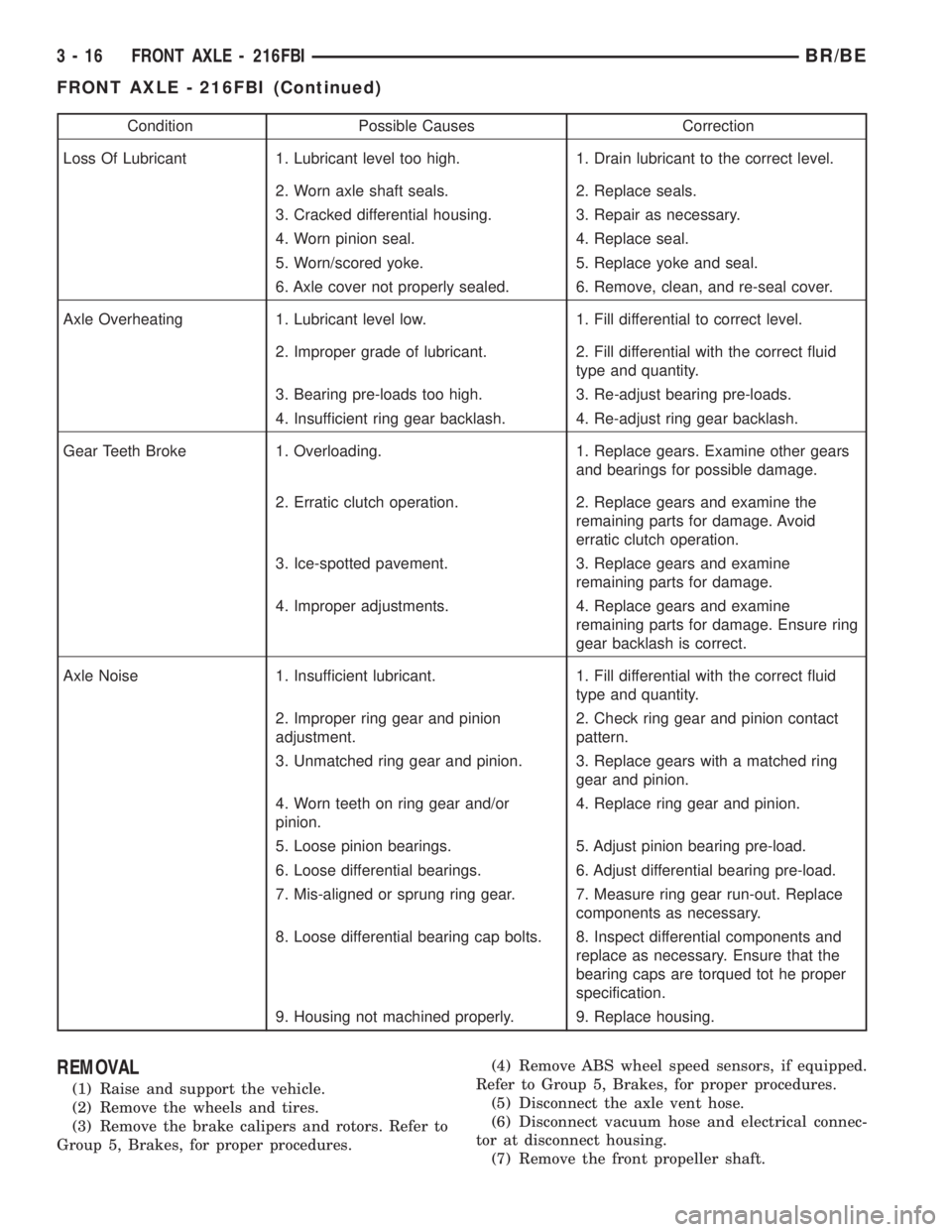
REMOVAL
(1) Raise and support the vehicle.
(2) Remove the wheels and tires.
(3) Remove the brake calipers and rotors. Refer to
Group 5, Brakes, for proper procedures.(4) Remove ABS wheel speed sensors, if equipped.
Refer to Group 5, Brakes, for proper procedures.
(5) Disconnect the axle vent hose.
(6) Disconnect vacuum hose and electrical connec-
tor at disconnect housing.
(7) Remove the front propeller shaft.
3 - 16 FRONT AXLE - 216FBIBR/BE
FRONT AXLE - 216FBI (Continued)
Page 90 of 2889

(8) Disconnect the stabilizer bar links at the axle
brackets.
(9) Disconnect the shock absorbers from axle
brackets.
(10) Disconnect the track bar from the axle
bracket.
(11) Disconnect the tie rod and drag link from the
steering knuckles.
(12) Position the axle with a suitable lifting device
under the axle assembly.
(13) Secure axle to lifting device.
(14) Mark suspension alignment cams for installa-
tion reference.
(15) Disconnect the upper and lower suspension
arms from the axle bracket.
(16) Lower the axle. The coil springs will drop
with the axle.
(17) Remove the coil springs from the axle bracket.
INSTALLATION
CAUTION: Suspension components with rubber
bushings should be tightened with the weight of the
vehicle on the suspension, at normal height. If
springs are not at their normal ride position, vehicle
ride comfort could be affected and premature bush-
ing wear may occur. Rubber bushings must never
be lubricated.
(1) Support the axle on a suitable lifting device.
(2) Secure axle to lifting device.
(3) Position the axle under the vehicle.
(4) Install the springs, retainer clip and bolts.
(5) Raise the axle and align it with the spring
pads.
(6) Position the upper and lower suspension arms
in the axle brackets. Install bolts, nuts and align the
suspension alignment cams to the reference marks.
Do not tighten at this time.
(7) Connect the track bar to the axle bracket and
install the bolt. Do not tighten at this time.
(8) Install the shock absorber and tighten bolts to
121 N´m (89 ft. lbs.) torque.
(9) Install the stabilizer bar link to the axle
bracket. Tighten the nut to 37 N´m (27 ft. lbs.)
torque.
(10) Install the drag link and tie rod to the steer-
ing knuckles and tighten the nuts to 88 N´m (65 ft.
lbs.) torque.
(11) Install the ABS wheel speed sensors, if
equipped. Refer to group 5, Brakes, for proper proce-
dures.
(12) Install the brake calipers and rotors. Refer to
Group 5, Brakes, for proper procedures.
(13) Connect the vent hose to the tube fitting.
(14) Connect vacuum hose and electrical connector
to disconnect housing.(15) Install front propeller shaft.
(16) Check and add differential lubricant, if neces-
sary. Refer to Lubricant Specifications in this section
for lubricant requirements.
(17) Install the wheel and tire assemblies.
(18) Remove the supports and lower the vehicle.
(19) Tighten the upper suspension arm nuts at
axle to 121 N´m (89 ft. lbs.) torque. Tighten the
upper suspension arm nuts at frame to 84 N´m (62 ft.
lbs.) torque.
(20) Tighten the lower suspension arm nuts at
axle to 84 N´m (62 ft. lbs.) torque. Tighten the lower
suspension arm nuts at frame to 119 N´m (88 ft. lbs.)
torque.
(21) Tighten the track bar bolt at the axle bracket
to 176 N´m (130 ft. lbs.) torque.
(22) Check the front wheel alignment.
ADJUSTMENTS
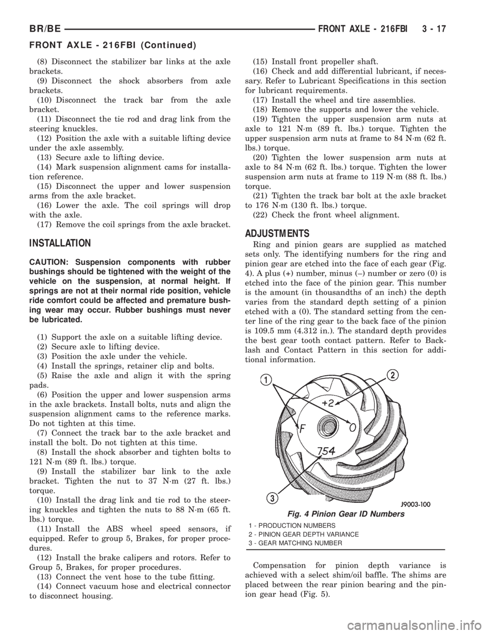
Ring and pinion gears are supplied as matched
sets only. The identifying numbers for the ring and
pinion gear are etched into the face of each gear (Fig.
4). A plus (+) number, minus (±) number or zero (0) is
etched into the face of the pinion gear. This number
is the amount (in thousandths of an inch) the depth
varies from the standard depth setting of a pinion
etched with a (0). The standard setting from the cen-
ter line of the ring gear to the back face of the pinion
is 109.5 mm (4.312 in.). The standard depth provides
the best gear tooth contact pattern. Refer to Back-
lash and Contact Pattern in this section for addi-
tional information.
Compensation for pinion depth variance is
achieved with a select shim/oil baffle. The shims are
placed between the rear pinion bearing and the pin-
ion gear head (Fig. 5).
Fig. 4 Pinion Gear ID Numbers
1 - PRODUCTION NUMBERS
2 - PINION GEAR DEPTH VARIANCE
3 - GEAR MATCHING NUMBER
BR/BEFRONT AXLE - 216FBI 3 - 17
FRONT AXLE - 216FBI (Continued)
Page 101 of 2889

AXLE SHAFTS
REMOVAL
(1) Raise and support the vehicle.
(2) Remove wheel and tire assembly.
(3) Remove brake caliper and rotor. Refer to
Brakes for procedures.
(4) Remove ABS wheel speed sensor if equipped.
Refer to Brakes for procedures.
(5) Remove the cotter pin and axle hub nut.
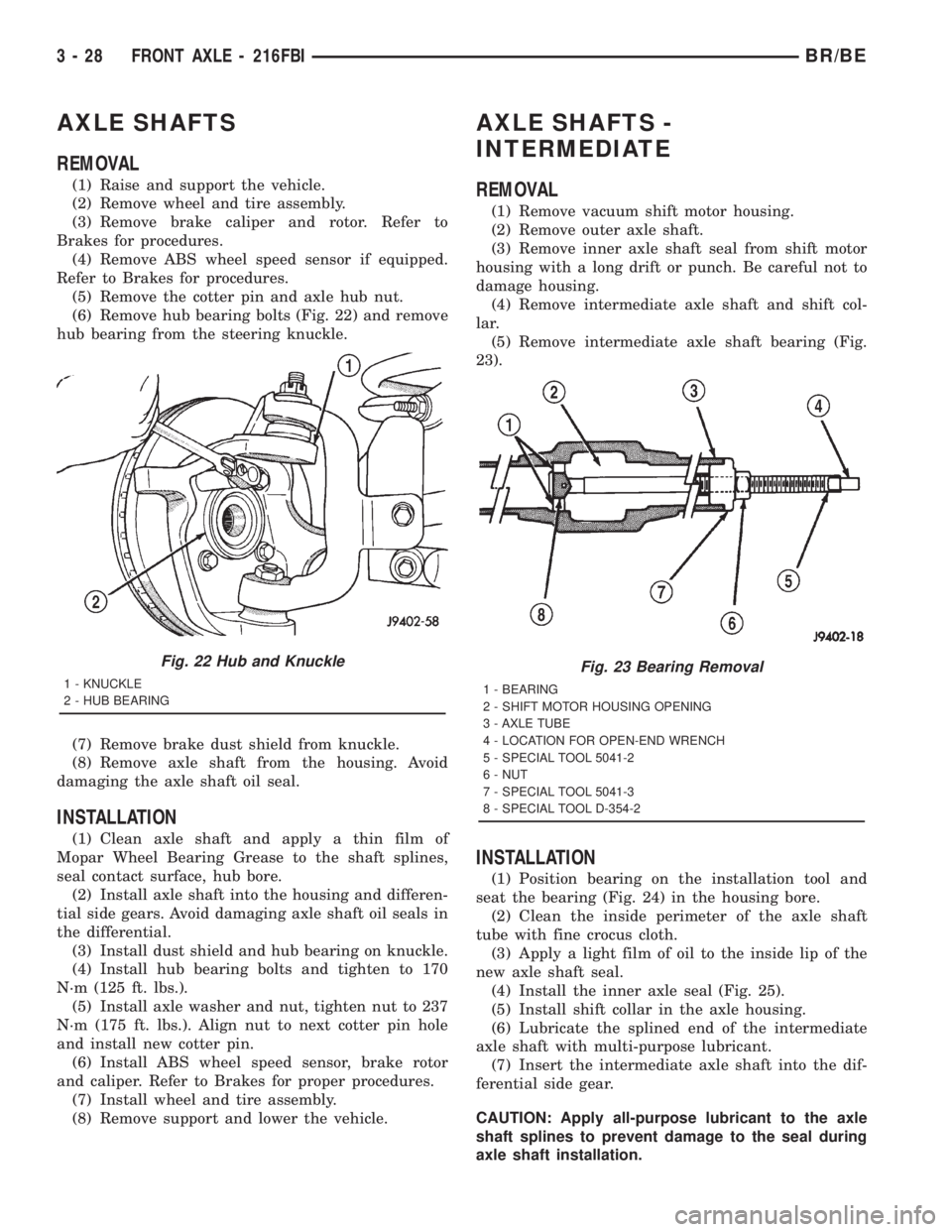
(6) Remove hub bearing bolts (Fig. 22) and remove
hub bearing from the steering knuckle.
(7) Remove brake dust shield from knuckle.
(8) Remove axle shaft from the housing. Avoid
damaging the axle shaft oil seal.
INSTALLATION
(1) Clean axle shaft and apply a thin film of
Mopar Wheel Bearing Grease to the shaft splines,
seal contact surface, hub bore.
(2) Install axle shaft into the housing and differen-
tial side gears. Avoid damaging axle shaft oil seals in
the differential.
(3) Install dust shield and hub bearing on knuckle.
(4) Install hub bearing bolts and tighten to 170
N´m (125 ft. lbs.).
(5) Install axle washer and nut, tighten nut to 237
N´m (175 ft. lbs.). Align nut to next cotter pin hole
and install new cotter pin.
(6) Install ABS wheel speed sensor, brake rotor
and caliper. Refer to Brakes for proper procedures.
(7) Install wheel and tire assembly.
(8) Remove support and lower the vehicle.
AXLE SHAFTS -
INTERMEDIATE
REMOVAL
(1) Remove vacuum shift motor housing.
(2) Remove outer axle shaft.
(3) Remove inner axle shaft seal from shift motor
housing with a long drift or punch. Be careful not to
damage housing.
(4) Remove intermediate axle shaft and shift col-
lar.
(5) Remove intermediate axle shaft bearing (Fig.
23).
INSTALLATION
(1) Position bearing on the installation tool and
seat the bearing (Fig. 24) in the housing bore.
(2) Clean the inside perimeter of the axle shaft
tube with fine crocus cloth.
(3) Apply a light film of oil to the inside lip of the
new axle shaft seal.
(4) Install the inner axle seal (Fig. 25).
(5) Install shift collar in the axle housing.
(6) Lubricate the splined end of the intermediate
axle shaft with multi-purpose lubricant.
(7) Insert the intermediate axle shaft into the dif-
ferential side gear.
CAUTION: Apply all-purpose lubricant to the axle
shaft splines to prevent damage to the seal during
axle shaft installation.
Fig. 22 Hub and Knuckle
1 - KNUCKLE
2 - HUB BEARING
Fig. 23 Bearing Removal
1 - BEARING
2 - SHIFT MOTOR HOUSING OPENING
3 - AXLE TUBE
4 - LOCATION FOR OPEN-END WRENCH
5 - SPECIAL TOOL 5041-2
6 - NUT
7 - SPECIAL TOOL 5041-3
8 - SPECIAL TOOL D-354-2
3 - 28 FRONT AXLE - 216FBIBR/BE
Page 107 of 2889

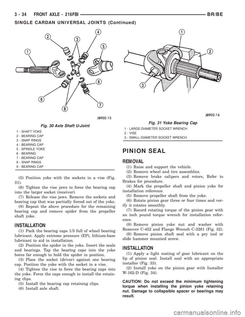
(5) Position yoke with the sockets in a vise (Fig.
31).
(6) Tighten the vise jaws to force the bearing cap
into the larger socket (receiver).
(7) Release the vise jaws. Remove the sockets and
bearing cap that was partially forced out of the yoke.
(8) Repeat the above procedure for the remaining
bearing cap and remove spider from the propeller
shaft yoke.
INSTALLATION
(1) Pack the bearing caps 1/3 full of wheel bearing
lubricant. Apply extreme pressure (EP), lithium-base
lubricant to aid in installation.
(2) Position the spider in the yoke. Insert the seals
and bearings. Tap the bearing caps into the yoke
bores far enough to hold the spider in position.
(3) Place the socket (driver) against one bearing
cap. Position the yoke with the socket in a vise.
(4) Tighten the vise to force the bearing caps into
the yoke. Force the caps enough to install the retain-
ing clips.
(5) Install the bearing cap retaining clips.
(6) Install axle shaft.
PINION SEAL
REMOVAL
(1) Raise and support the vehicle.
(2) Remove wheel and tire assemblies.
(3) Remove brake calipers and rotors, Refer to
Brakes for procedure.
(4) Mark the propeller shaft and pinion yoke for
installation reference.
(5) Remove propeller shaft from the yoke.
(6) Rotate pinion gear three or four times and ver-
ify it rotates smoothly.
(7) Record rotating torque of the pinion gear with
an inch pound torque wrench for installation refer-
ence.
(8) Remove pinion yoke nut and washer with
Remover C-452 and Flange Wrench C-3281 (Fig. 32).
(9) Remove pinion shaft seal with a pry tool or
slide hammer mounted screw.
INSTALLATION
(1) Apply a light coating of gear lubricant on the
lip of pinion seal. Install seal with an appropriate
installer (Fig. 33).
(2) Install yoke on the pinion gear with Installer
W-162-D (Fig. 34).
CAUTION: Do not exceed the minimum tightening
torque when installing the pinion yoke retaining
nut. Damage to collapsible spacer or bearings may
result.
Fig. 30 Axle Shaft U-Joint
1 - SHAFT YOKE
2 - BEARING CAP
3 - SNAP RINGS
4 - BEARING CAP
5 - SPINDLE YOKE
6 - BEARING
7 - BEARING CAP
8 - SNAP RINGS
9 - BEARING CAP
Fig. 31 Yoke Bearing Cap
1 - LARGE-DIAMETER SOCKET WRENCH
2 - VISE
3 - SMALL-DIAMETER SOCKET WRENCH
3 - 34 FRONT AXLE - 216FBIBR/BE
SINGLE CARDAN UNIVERSAL JOINTS (Continued)