2001 DODGE RAM coolant reservoir
[x] Cancel search: coolant reservoirPage 395 of 2889
CAUTION: A number or letter is stamped into the
tongue of constant tension clamps. If replacement
is necessary, use only an original equipment clamp
with a matching number or letter.
(3) Remove hose clamps and hoses from radiator.
(4) Remove coolant reserve/overflow tank hose
from radiator filler neck nipple.
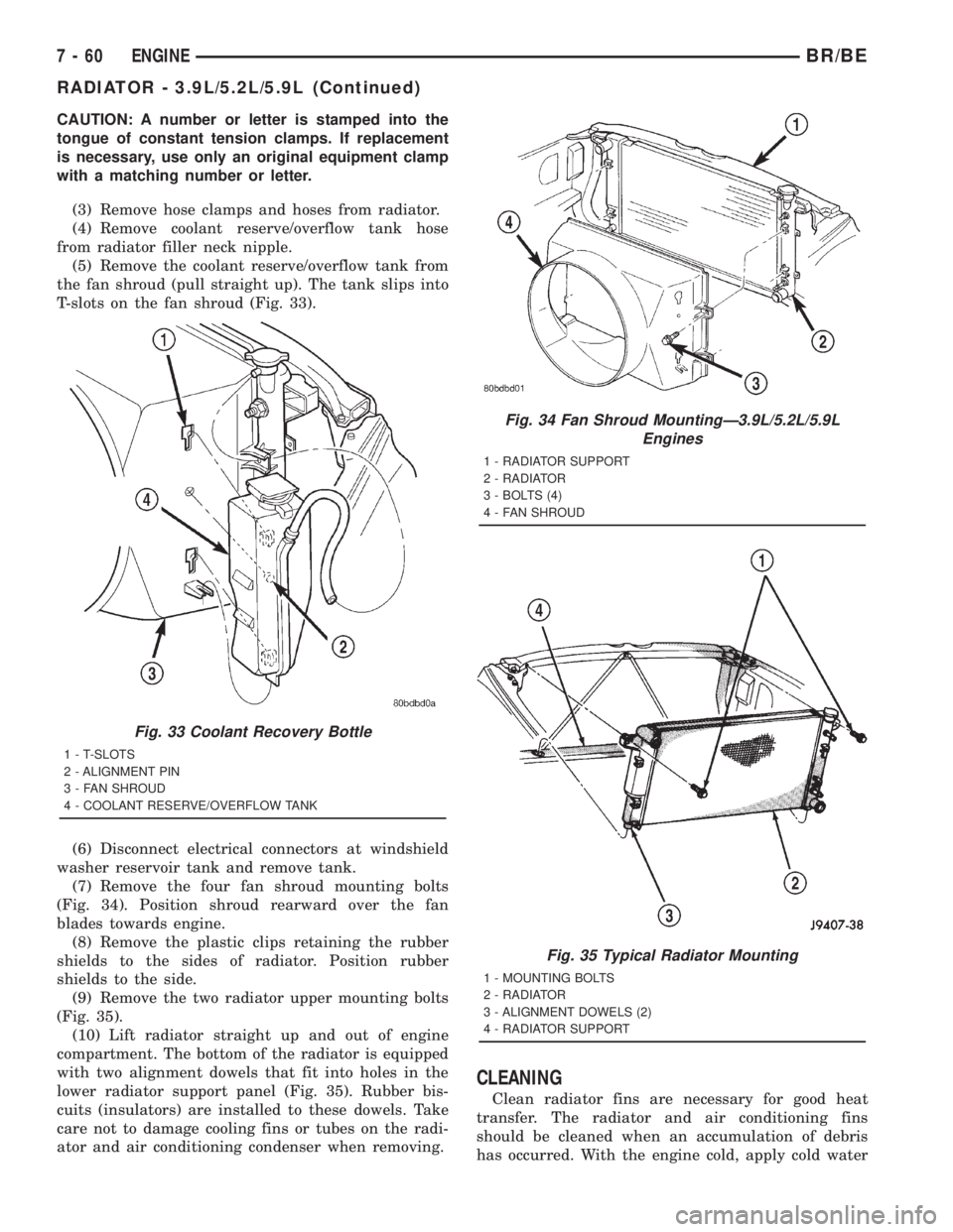
(5) Remove the coolant reserve/overflow tank from
the fan shroud (pull straight up). The tank slips into
T-slots on the fan shroud (Fig. 33).
(6) Disconnect electrical connectors at windshield
washer reservoir tank and remove tank.
(7) Remove the four fan shroud mounting bolts
(Fig. 34). Position shroud rearward over the fan
blades towards engine.
(8) Remove the plastic clips retaining the rubber
shields to the sides of radiator. Position rubber
shields to the side.
(9) Remove the two radiator upper mounting bolts
(Fig. 35).
(10) Lift radiator straight up and out of engine
compartment. The bottom of the radiator is equipped
with two alignment dowels that fit into holes in the
lower radiator support panel (Fig. 35). Rubber bis-
cuits (insulators) are installed to these dowels. Take
care not to damage cooling fins or tubes on the radi-
ator and air conditioning condenser when removing.
CLEANING
Clean radiator fins are necessary for good heat
transfer. The radiator and air conditioning fins
should be cleaned when an accumulation of debris
has occurred. With the engine cold, apply cold water
Fig. 33 Coolant Recovery Bottle
1 - T-SLOTS
2 - ALIGNMENT PIN
3 - FAN SHROUD
4 - COOLANT RESERVE/OVERFLOW TANK
Fig. 34 Fan Shroud MountingÐ3.9L/5.2L/5.9L
Engines
1 - RADIATOR SUPPORT
2 - RADIATOR
3 - BOLTS (4)
4 - FAN SHROUD
Fig. 35 Typical Radiator Mounting
1 - MOUNTING BOLTS
2 - RADIATOR
3 - ALIGNMENT DOWELS (2)
4 - RADIATOR SUPPORT
7 - 60 ENGINEBR/BE
RADIATOR - 3.9L/5.2L/5.9L (Continued)
Page 396 of 2889
and compressed air to the back (engine side) of the
radiator to flush the radiator and/or A/C condenser of
debris.
INSPECTION
Inspect the radiator side tanks for cracks, broken
or missing fittings also inspect the joint where the
tanks seam up to the radiator core for signs of leak-
age and/or deteriorating seals.
Inspect radiator core for corroded, bent or missing
cooling fins. Inspect the core for bent or damaged
cooling tubes.
INSTALLATION
(1) Position fan shroud over the fan blades rear-
ward towards engine.
(2) Install rubber insulators to alignment dowels
at lower part of radiator.
(3) Lower the radiator into position while guiding
the two alignment dowels into lower radiator sup-
port. Different alignment holes are provided in the
lower radiator support for each engine application.
(4) Install two upper radiator mounting bolts.
Tighten bolts to 11 N´m (95 in. lbs.) torque.
(5) Position the rubber shields to the sides of radi-
ator. Install the plastic clips retaining the rubber
shields to the sides of radiator.
(6) Connect both radiator hoses and install hose
clamps.
(7) Install windshield washer reservoir tank.
(8) Position fan shroud to flanges on sides of radi-
ator. Install fan shroud mounting bolts (Fig. 34).
Tighten bolts to 6 N´m (50 in. lbs.) torque.
(9) Install coolant reserve/overflow tank hose to
radiator filler neck nipple.
(10) Install coolant reserve/overflow tank to fan
shroud (fits into T-slots on shroud).
(11) Install battery negative cables.
(12) Position heater controls tofull heatposition.
(13) Fill cooling system with coolant (Refer to 7 -
COOLING - STANDARD PROCEDURE).
(14) Operate engine until it reaches normal tem-
perature. Check cooling system fluid levels.
RADIATOR - 8.0L
DESCRIPTION
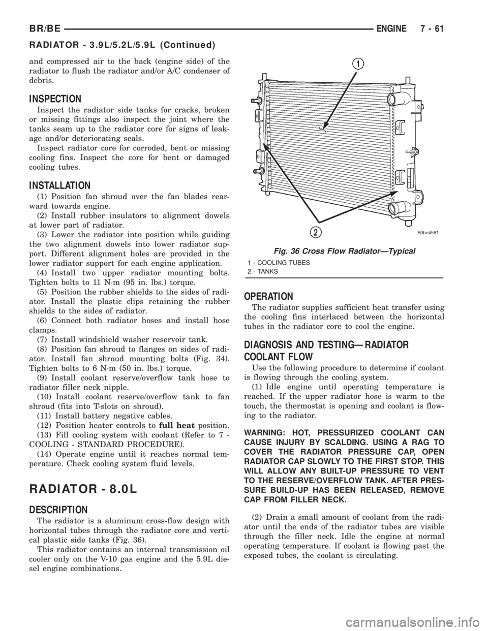
The radiator is a aluminum cross-flow design with
horizontal tubes through the radiator core and verti-
cal plastic side tanks (Fig. 36).
This radiator contains an internal transmission oil
cooler only on the V-10 gas engine and the 5.9L die-
sel engine combinations.
OPERATION
The radiator supplies sufficient heat transfer using
the cooling fins interlaced between the horizontal
tubes in the radiator core to cool the engine.
DIAGNOSIS AND TESTINGÐRADIATOR
COOLANT FLOW
Use the following procedure to determine if coolant
is flowing through the cooling system.
(1) Idle engine until operating temperature is
reached. If the upper radiator hose is warm to the
touch, the thermostat is opening and coolant is flow-
ing to the radiator.
WARNING: HOT, PRESSURIZED COOLANT CAN
CAUSE INJURY BY SCALDING. USING A RAG TO
COVER THE RADIATOR PRESSURE CAP, OPEN
RADIATOR CAP SLOWLY TO THE FIRST STOP. THIS
WILL ALLOW ANY BUILT-UP PRESSURE TO VENT
TO THE RESERVE/OVERFLOW TANK. AFTER PRES-
SURE BUILD-UP HAS BEEN RELEASED, REMOVE
CAP FROM FILLER NECK.
(2) Drain a small amount of coolant from the radi-
ator until the ends of the radiator tubes are visible
through the filler neck. Idle the engine at normal
operating temperature. If coolant is flowing past the
exposed tubes, the coolant is circulating.
Fig. 36 Cross Flow RadiatorÐTypical
1 - COOLING TUBES
2 - TANKS
BR/BEENGINE 7 - 61
RADIATOR - 3.9L/5.2L/5.9L (Continued)
Page 397 of 2889
REMOVAL
(1) Disconnect battery negative cables.
WARNING: DO NOT REMOVE THE CYLINDER
BLOCK DRAIN PLUGS OR LOOSEN THE RADIATOR
DRAINCOCK WITH THE SYSTEM HOT AND UNDER
PRESSURE. SERIOUS BURNS FROM COOLANT
CAN OCCUR.
(2) Drain the cooling system (Refer to 7 - COOL-
ING - STANDARD PROCEDURE).
WARNING: CONSTANT TENSION HOSE CLAMPS
ARE USED ON MOST COOLING SYSTEM HOSES.
WHEN REMOVING OR INSTALLING, USE ONLY
TOOLS DESIGNED FOR SERVICING THIS TYPE OF
CLAMP, SUCH AS SPECIAL CLAMP TOOL (NUMBER
6094). SNAP-ON CLAMP TOOL (NUMBER HPC-20)
MAY BE USED FOR LARGER CLAMPS. ALWAYS
WEAR SAFETY GLASSES WHEN SERVICING CON-
STANT TENSION CLAMPS.
CAUTION: A number or letter is stamped into the
tongue of constant tension clamps. If replacement
is necessary, use only an original equipment clamp
with a matching number or letter.
(3) Remove hose clamps and hoses from radiator.
(4) Remove coolant reserve/overflow tank hose
from radiator filler neck nipple.
(5) The coolant recovery/reservoir does not require
removal. Disconnect the overflow hose from the radi-
ator.
(6) Disconnect electrical connectors at windshield
washer reservoir tank and remove tank.
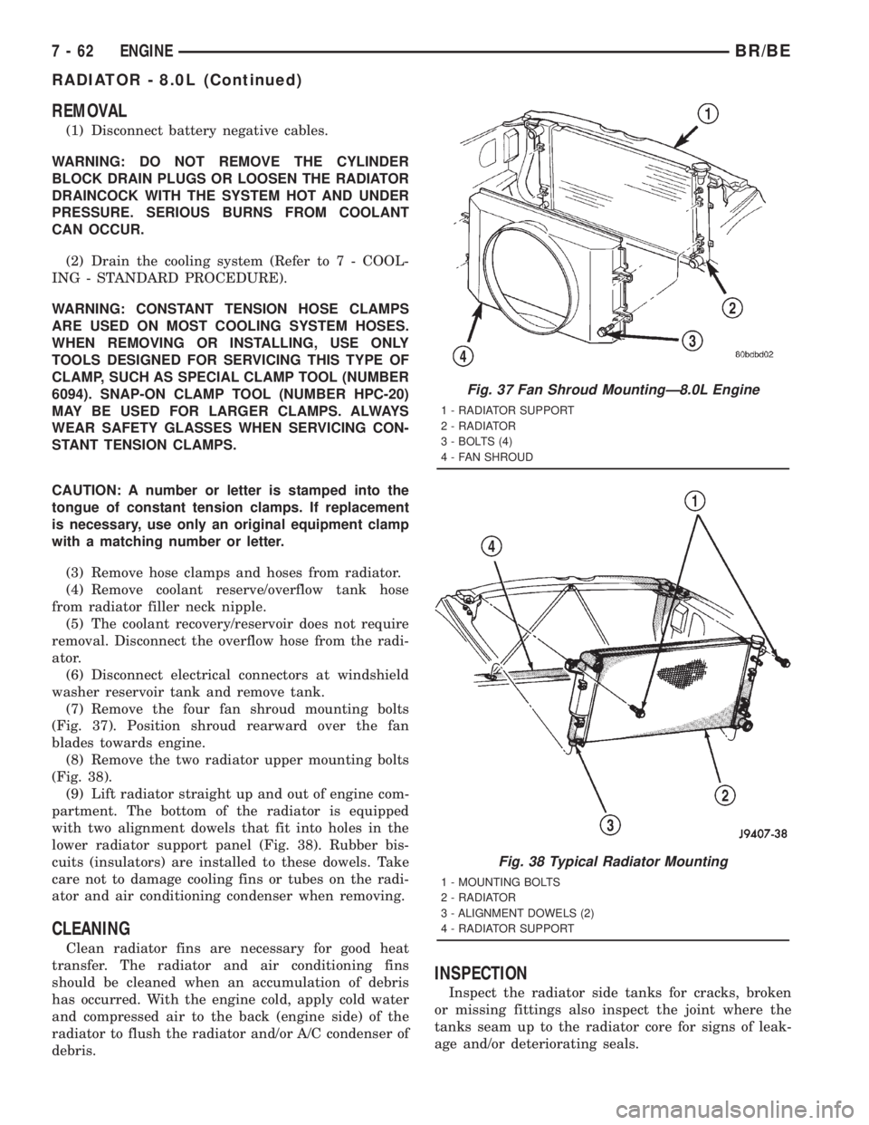
(7) Remove the four fan shroud mounting bolts
(Fig. 37). Position shroud rearward over the fan
blades towards engine.
(8) Remove the two radiator upper mounting bolts
(Fig. 38).
(9) Lift radiator straight up and out of engine com-
partment. The bottom of the radiator is equipped
with two alignment dowels that fit into holes in the
lower radiator support panel (Fig. 38). Rubber bis-
cuits (insulators) are installed to these dowels. Take
care not to damage cooling fins or tubes on the radi-
ator and air conditioning condenser when removing.
CLEANING
Clean radiator fins are necessary for good heat
transfer. The radiator and air conditioning fins
should be cleaned when an accumulation of debris
has occurred. With the engine cold, apply cold water
and compressed air to the back (engine side) of the
radiator to flush the radiator and/or A/C condenser of
debris.
INSPECTION
Inspect the radiator side tanks for cracks, broken
or missing fittings also inspect the joint where the
tanks seam up to the radiator core for signs of leak-
age and/or deteriorating seals.
Fig. 37 Fan Shroud MountingÐ8.0L Engine
1 - RADIATOR SUPPORT
2 - RADIATOR
3 - BOLTS (4)
4 - FAN SHROUD
Fig. 38 Typical Radiator Mounting
1 - MOUNTING BOLTS
2 - RADIATOR
3 - ALIGNMENT DOWELS (2)
4 - RADIATOR SUPPORT
7 - 62 ENGINEBR/BE
RADIATOR - 8.0L (Continued)
Page 398 of 2889
Inspect radiator core for corroded, bent or missing
cooling fins. Inspect the core for bent or damaged
cooling tubes.
INSTALLATION
(1) Position fan shroud over the fan blades rear-
ward towards engine.
(2) Install rubber insulators to alignment dowels
at lower part of radiator.
(3) Lower the radiator into position while guiding
the two alignment dowels into lower radiator sup-
port. Different alignment holes are provided in the
lower radiator support for each engine application.
(4) Install two upper radiator mounting bolts.
Tighten bolts to 11 N´m (95 in. lbs.) torque.
(5) Connect both radiator hoses and install hose
clamps.
(6) Install windshield washer reservoir tank.
(7) Position fan shroud to flanges on sides of radi-
ator. Install fan shroud mounting bolts (Fig. 37).
Tighten bolts to 6 N´m (50 in. lbs.) torque.
(8) Install coolant reserve/overflow tank hose to
radiator filler neck nipple.
(9) Connect the overflow hose to the radiator.
(10) Install battery negative cables.
(11) Position heater controls tofull heatposition.
(12) Fill cooling system with coolant (Refer to 7 -
COOLING - STANDARD PROCEDURE).
(13) Operate engine until it reaches normal tem-
perature. Check cooling system fluid levels.
RADIATOR - 5.9L DIESEL
DESCRIPTION
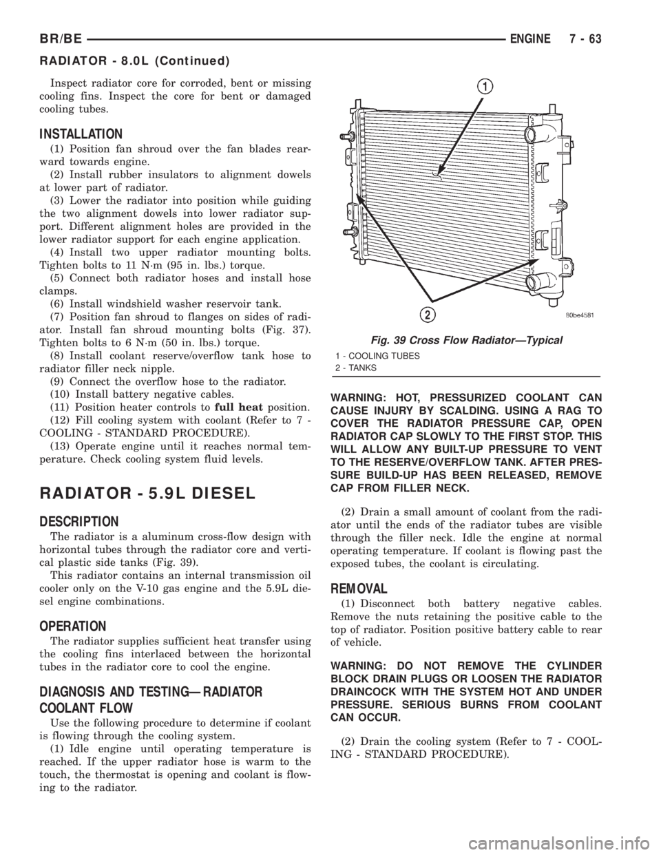
The radiator is a aluminum cross-flow design with
horizontal tubes through the radiator core and verti-
cal plastic side tanks (Fig. 39).
This radiator contains an internal transmission oil
cooler only on the V-10 gas engine and the 5.9L die-
sel engine combinations.
OPERATION
The radiator supplies sufficient heat transfer using
the cooling fins interlaced between the horizontal
tubes in the radiator core to cool the engine.
DIAGNOSIS AND TESTINGÐRADIATOR
COOLANT FLOW
Use the following procedure to determine if coolant
is flowing through the cooling system.
(1) Idle engine until operating temperature is
reached. If the upper radiator hose is warm to the
touch, the thermostat is opening and coolant is flow-
ing to the radiator.WARNING: HOT, PRESSURIZED COOLANT CAN
CAUSE INJURY BY SCALDING. USING A RAG TO
COVER THE RADIATOR PRESSURE CAP, OPEN
RADIATOR CAP SLOWLY TO THE FIRST STOP. THIS
WILL ALLOW ANY BUILT-UP PRESSURE TO VENT
TO THE RESERVE/OVERFLOW TANK. AFTER PRES-
SURE BUILD-UP HAS BEEN RELEASED, REMOVE
CAP FROM FILLER NECK.
(2) Drain a small amount of coolant from the radi-
ator until the ends of the radiator tubes are visible
through the filler neck. Idle the engine at normal
operating temperature. If coolant is flowing past the
exposed tubes, the coolant is circulating.
REMOVAL
(1) Disconnect both battery negative cables.
Remove the nuts retaining the positive cable to the
top of radiator. Position positive battery cable to rear
of vehicle.
WARNING: DO NOT REMOVE THE CYLINDER
BLOCK DRAIN PLUGS OR LOOSEN THE RADIATOR
DRAINCOCK WITH THE SYSTEM HOT AND UNDER
PRESSURE. SERIOUS BURNS FROM COOLANT
CAN OCCUR.
(2) Drain the cooling system (Refer to 7 - COOL-
ING - STANDARD PROCEDURE).
Fig. 39 Cross Flow RadiatorÐTypical
1 - COOLING TUBES
2 - TANKS
BR/BEENGINE 7 - 63
RADIATOR - 8.0L (Continued)
Page 399 of 2889
WARNING: CONSTANT TENSION HOSE CLAMPS
ARE USED ON MOST COOLING SYSTEM HOSES.
WHEN REMOVING OR INSTALLING, USE ONLY
TOOLS DESIGNED FOR SERVICING THIS TYPE OF
CLAMP, SUCH AS SPECIAL CLAMP TOOL (NUMBER
6094). SNAP-ON CLAMP TOOL (NUMBER HPC-20)
MAY BE USED FOR LARGER CLAMPS. ALWAYS
WEAR SAFETY GLASSES WHEN SERVICING CON-
STANT TENSION CLAMPS.
CAUTION: A number or letter is stamped into the
tongue of constant tension clamps. If replacement
is necessary, use only an original equipment clamp
with a matching number or letter.
(3) Remove hose clamps and hoses from radiator.
(4) Remove coolant reserve/overflow tank hose
from radiator filler neck nipple.
(5) Remove the coolant reserve/overflow tank from
the fan shroud (pull straight up). The tank slips into
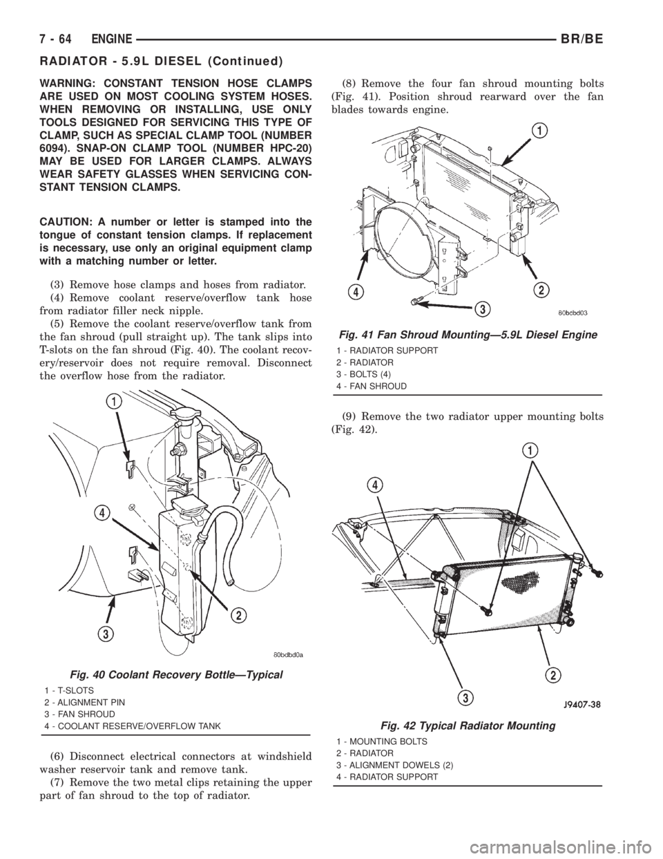
T-slots on the fan shroud (Fig. 40). The coolant recov-
ery/reservoir does not require removal. Disconnect
the overflow hose from the radiator.
(6) Disconnect electrical connectors at windshield
washer reservoir tank and remove tank.
(7) Remove the two metal clips retaining the upper
part of fan shroud to the top of radiator.(8) Remove the four fan shroud mounting bolts
(Fig. 41). Position shroud rearward over the fan
blades towards engine.
(9) Remove the two radiator upper mounting bolts
(Fig. 42).
Fig. 40 Coolant Recovery BottleÐTypical
1 - T-SLOTS
2 - ALIGNMENT PIN
3 - FAN SHROUD
4 - COOLANT RESERVE/OVERFLOW TANK
Fig. 41 Fan Shroud MountingÐ5.9L Diesel Engine
1 - RADIATOR SUPPORT
2 - RADIATOR
3 - BOLTS (4)
4 - FAN SHROUD
Fig. 42 Typical Radiator Mounting
1 - MOUNTING BOLTS
2 - RADIATOR
3 - ALIGNMENT DOWELS (2)
4 - RADIATOR SUPPORT
7 - 64 ENGINEBR/BE
RADIATOR - 5.9L DIESEL (Continued)
Page 400 of 2889
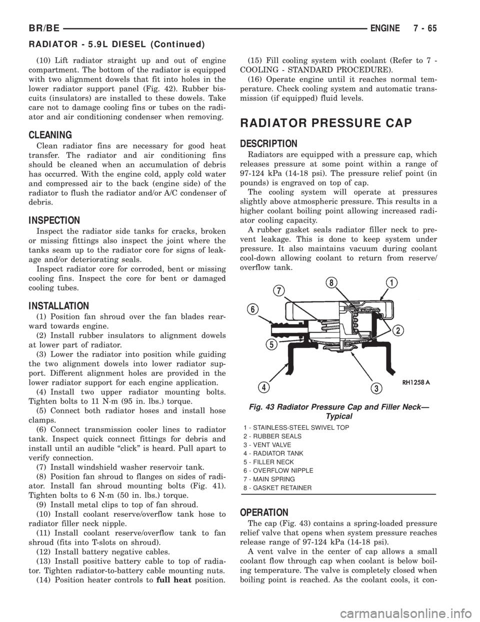
(10) Lift radiator straight up and out of engine
compartment. The bottom of the radiator is equipped
with two alignment dowels that fit into holes in the
lower radiator support panel (Fig. 42). Rubber bis-
cuits (insulators) are installed to these dowels. Take
care not to damage cooling fins or tubes on the radi-
ator and air conditioning condenser when removing.
CLEANING
Clean radiator fins are necessary for good heat
transfer. The radiator and air conditioning fins
should be cleaned when an accumulation of debris
has occurred. With the engine cold, apply cold water
and compressed air to the back (engine side) of the
radiator to flush the radiator and/or A/C condenser of
debris.
INSPECTION
Inspect the radiator side tanks for cracks, broken
or missing fittings also inspect the joint where the
tanks seam up to the radiator core for signs of leak-
age and/or deteriorating seals.
Inspect radiator core for corroded, bent or missing
cooling fins. Inspect the core for bent or damaged
cooling tubes.
INSTALLATION
(1) Position fan shroud over the fan blades rear-
ward towards engine.
(2) Install rubber insulators to alignment dowels
at lower part of radiator.
(3) Lower the radiator into position while guiding
the two alignment dowels into lower radiator sup-
port. Different alignment holes are provided in the
lower radiator support for each engine application.
(4) Install two upper radiator mounting bolts.
Tighten bolts to 11 N´m (95 in. lbs.) torque.
(5) Connect both radiator hoses and install hose
clamps.
(6) Connect transmission cooler lines to radiator
tank. Inspect quick connect fittings for debris and
install until an audible ªclickº is heard. Pull apart to
verify connection.
(7) Install windshield washer reservoir tank.
(8) Position fan shroud to flanges on sides of radi-
ator. Install fan shroud mounting bolts (Fig. 41).
Tighten bolts to 6 N´m (50 in. lbs.) torque.
(9) Install metal clips to top of fan shroud.
(10) Install coolant reserve/overflow tank hose to
radiator filler neck nipple.
(11) Install coolant reserve/overflow tank to fan
shroud (fits into T-slots on shroud).
(12) Install battery negative cables.
(13) Install positive battery cable to top of radia-
tor. Tighten radiator-to-battery cable mounting nuts.
(14) Position heater controls tofull heatposition.(15) Fill cooling system with coolant (Refer to 7 -
COOLING - STANDARD PROCEDURE).
(16) Operate engine until it reaches normal tem-
perature. Check cooling system and automatic trans-
mission (if equipped) fluid levels.
RADIATOR PRESSURE CAP
DESCRIPTION
Radiators are equipped with a pressure cap, which
releases pressure at some point within a range of
97-124 kPa (14-18 psi). The pressure relief point (in
pounds) is engraved on top of cap.
The cooling system will operate at pressures
slightly above atmospheric pressure. This results in a
higher coolant boiling point allowing increased radi-
ator cooling capacity.
A rubber gasket seals radiator filler neck to pre-
vent leakage. This is done to keep system under
pressure. It also maintains vacuum during coolant
cool-down allowing coolant to return from reserve/
overflow tank.
OPERATION
The cap (Fig. 43) contains a spring-loaded pressure
relief valve that opens when system pressure reaches
release range of 97-124 kPa (14-18 psi).
A vent valve in the center of cap allows a small
coolant flow through cap when coolant is below boil-
ing temperature. The valve is completely closed when
boiling point is reached. As the coolant cools, it con-
Fig. 43 Radiator Pressure Cap and Filler NeckÐ
Typical
1 - STAINLESS-STEEL SWIVEL TOP
2 - RUBBER SEALS
3 - VENT VALVE
4 - RADIATOR TANK
5 - FILLER NECK
6 - OVERFLOW NIPPLE
7 - MAIN SPRING
8 - GASKET RETAINER
BR/BEENGINE 7 - 65
RADIATOR - 5.9L DIESEL (Continued)
Page 402 of 2889
ket has swollen and prevents vent valve from open-
ing, replace cap.
Hold cap at eye level, upside down. If any light can
be seen between vent valve and rubber gasket,
replace cap.Do not use a replacement cap that
has a spring to hold vent shut.A replacement cap
must be the type designed for a coolant reserve/over-
flow system with a completely sealed diaphragm
spring and a rubber gasket. This gasket is used to
seal to radiator filler neck top surface. Use of proper
cap will allow coolant return to radiator.
WATER PUMP - 3.9L/5.2L/5.9L
DESCRIPTION
The water pump is located on the engine front
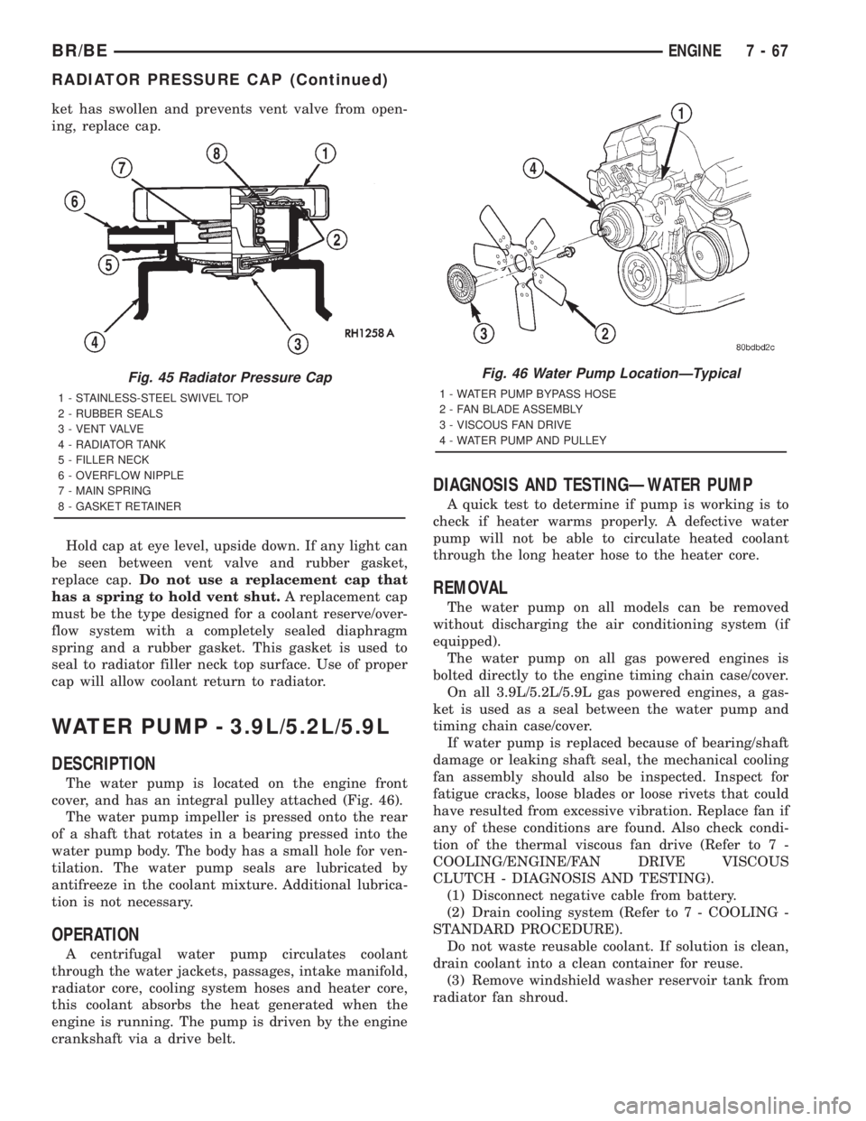
cover, and has an integral pulley attached (Fig. 46).
The water pump impeller is pressed onto the rear
of a shaft that rotates in a bearing pressed into the
water pump body. The body has a small hole for ven-
tilation. The water pump seals are lubricated by
antifreeze in the coolant mixture. Additional lubrica-
tion is not necessary.
OPERATION
A centrifugal water pump circulates coolant
through the water jackets, passages, intake manifold,
radiator core, cooling system hoses and heater core,
this coolant absorbs the heat generated when the
engine is running. The pump is driven by the engine
crankshaft via a drive belt.
DIAGNOSIS AND TESTINGÐWATER PUMP
A quick test to determine if pump is working is to
check if heater warms properly. A defective water
pump will not be able to circulate heated coolant
through the long heater hose to the heater core.
REMOVAL
The water pump on all models can be removed
without discharging the air conditioning system (if
equipped).
The water pump on all gas powered engines is
bolted directly to the engine timing chain case/cover.
On all 3.9L/5.2L/5.9L gas powered engines, a gas-
ket is used as a seal between the water pump and
timing chain case/cover.
If water pump is replaced because of bearing/shaft
damage or leaking shaft seal, the mechanical cooling
fan assembly should also be inspected. Inspect for
fatigue cracks, loose blades or loose rivets that could
have resulted from excessive vibration. Replace fan if
any of these conditions are found. Also check condi-
tion of the thermal viscous fan drive (Refer to 7 -
COOLING/ENGINE/FAN DRIVE VISCOUS
CLUTCH - DIAGNOSIS AND TESTING).
(1) Disconnect negative cable from battery.
(2) Drain cooling system (Refer to 7 - COOLING -
STANDARD PROCEDURE).
Do not waste reusable coolant. If solution is clean,
drain coolant into a clean container for reuse.
(3) Remove windshield washer reservoir tank from
radiator fan shroud.
Fig. 45 Radiator Pressure Cap
1 - STAINLESS-STEEL SWIVEL TOP
2 - RUBBER SEALS
3 - VENT VALVE
4 - RADIATOR TANK
5 - FILLER NECK
6 - OVERFLOW NIPPLE
7 - MAIN SPRING
8 - GASKET RETAINER
Fig. 46 Water Pump LocationÐTypical
1 - WATER PUMP BYPASS HOSE
2 - FAN BLADE ASSEMBLY
3 - VISCOUS FAN DRIVE
4 - WATER PUMP AND PULLEY
BR/BEENGINE 7 - 67
RADIATOR PRESSURE CAP (Continued)
Page 405 of 2889
INSTALLATION
(1) Clean gasket mating surfaces.
(2) Using a new gasket, install water pump to
engine as follows: Guide water pump nipple into
bypass hose as pump is being installed. Install water
pump bolts (Fig. 52). Tighten water pump mounting
bolts to 40 N´m (30 ft. lbs.) torque.
(3) Position bypass hose clamp to bypass hose.
(4) Spin water pump to be sure that pump impel-
ler does not rub against timing chain case/cover.
(5) Install a new o-ring to the heater hose coolant
return tube (Fig. 51). Coat the new o-ring with anti-
freeze before installation.
(6) Install coolant return tube and its mounting
bolt to engine (Fig. 51). Be sure the slot in tube
bracket is bottomed to mounting bolt. This will prop-
erly position return tube.
(7) Connect radiator lower hose to water pump.
(8) Connect heater hose and hose clamp to coolant
return tube.
(9) Install drive belt (Refer to 7 - COOLING/AC-
CESSORY DRIVE/DRIVE BELTS - INSTALLATION)
(Fig. 50).
(10) Position fan shroud and fan blade/viscous fan
drive assembly to vehicle as a complete unit.
(11) Install fan shroud.
(12) Install fan blade/viscous fan drive assembly to
water pump shaft.
(13) Fill cooling system (Refer to 7 - COOLING -
STANDARD PROCEDURE).
(14) Connect negative battery cable.
(15) Start and warm the engine. Check for leaks.
WATER PUMP - 8.0L
DIAGNOSIS AND TESTINGÐWATER PUMP
A quick test to determine if pump is working is to
check if heater warms properly. A defective water
pump will not be able to circulate heated coolant
through the long heater hose to the heater core.
REMOVAL
NOTE: The water pump on all models can be
removed without discharging the air conditioning
system (if equipped).
The water pump on all gas powered engines is
bolted directly to the engine timing chain case/
cover.
On the 8.0L V-10 engine, a rubber o-ring (instead of
a gasket) is used as a seal between the water pump
and timing chain case/cover.If water pump is replaced because of bearing/shaft
damage or leaking shaft seal, the mechanical cooling
fan assembly should also be inspected. Inspect for
fatigue cracks, loose blades or loose rivets that could
have resulted from excessive vibration. Replace fan if
any of these conditions are found. Also check condi-
tion of the thermal viscous fan drive (Refer to 7 -
COOLING/ENGINE/FAN DRIVE VISCOUS
CLUTCH - DIAGNOSIS AND TESTING).
(1) Disconnect negative battery cable from battery.
(2) Drain cooling system (Refer to 7 - COOLING -
STANDARD PROCEDURE).
Do not waste reusable coolant. If solution is clean,
drain coolant into a clean container for reuse.
(3) Remove windshield washer reservoir tank from
radiator fan shroud.
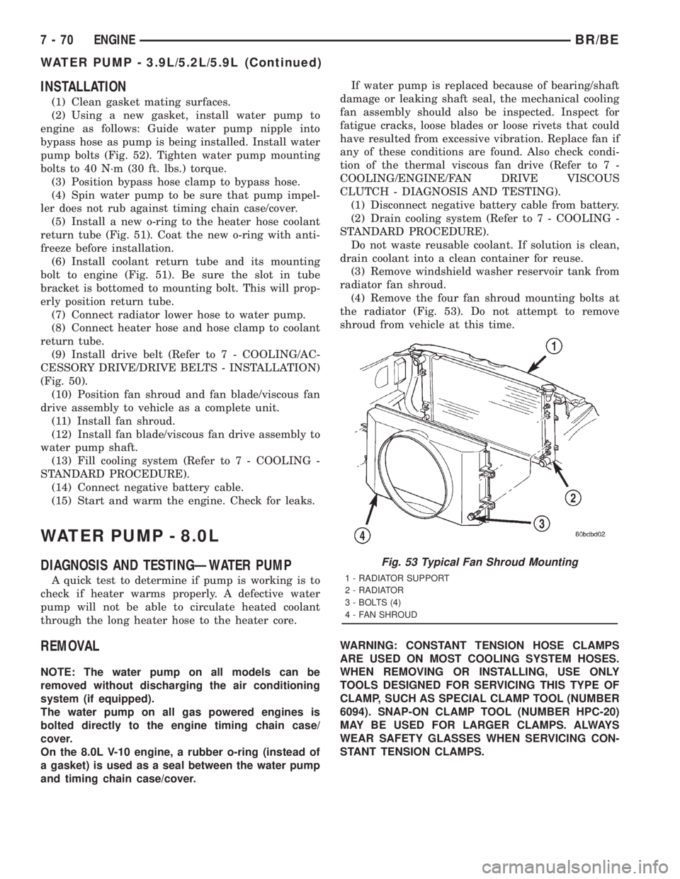
(4) Remove the four fan shroud mounting bolts at
the radiator (Fig. 53). Do not attempt to remove
shroud from vehicle at this time.
WARNING: CONSTANT TENSION HOSE CLAMPS
ARE USED ON MOST COOLING SYSTEM HOSES.
WHEN REMOVING OR INSTALLING, USE ONLY
TOOLS DESIGNED FOR SERVICING THIS TYPE OF
CLAMP, SUCH AS SPECIAL CLAMP TOOL (NUMBER
6094). SNAP-ON CLAMP TOOL (NUMBER HPC-20)
MAY BE USED FOR LARGER CLAMPS. ALWAYS
WEAR SAFETY GLASSES WHEN SERVICING CON-
STANT TENSION CLAMPS.
Fig. 53 Typical Fan Shroud Mounting
1 - RADIATOR SUPPORT
2 - RADIATOR
3 - BOLTS (4)
4 - FAN SHROUD
7 - 70 ENGINEBR/BE
WATER PUMP - 3.9L/5.2L/5.9L (Continued)