2001 DODGE RAM radiator
[x] Cancel search: radiatorPage 1451 of 2889
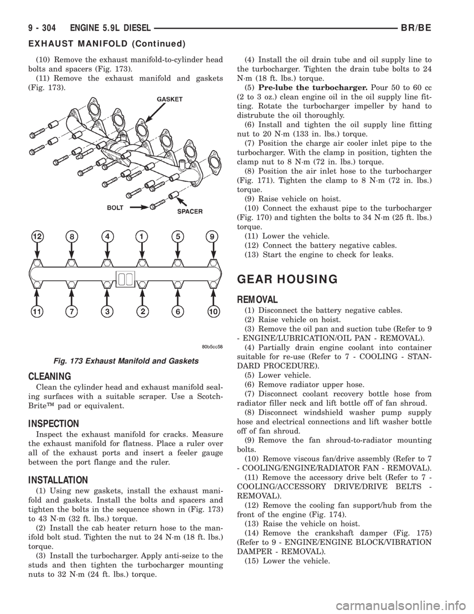
(10) Remove the exhaust manifold-to-cylinder head
bolts and spacers (Fig. 173).
(11) Remove the exhaust manifold and gaskets
(Fig. 173).
CLEANING
Clean the cylinder head and exhaust manifold seal-
ing surfaces with a suitable scraper. Use a Scotch-
BriteŸ pad or equivalent.
INSPECTION
Inspect the exhaust manifold for cracks. Measure
the exhaust manifold for flatness. Place a ruler over
all of the exhaust ports and insert a feeler gauge
between the port flange and the ruler.
INSTALLATION
(1) Using new gaskets, install the exhaust mani-
fold and gaskets. Install the bolts and spacers and
tighten the bolts in the sequence shown in (Fig. 173)
to 43 N´m (32 ft. lbs.) torque.
(2) Install the cab heater return hose to the man-
ifold bolt stud. Tighten the nut to 24 N´m (18 ft. lbs.)
torque.
(3) Install the turbocharger. Apply anti-seize to the
studs and then tighten the turbocharger mounting
nuts to 32 N´m (24 ft. lbs.) torque.(4) Install the oil drain tube and oil supply line to
the turbocharger. Tighten the drain tube bolts to 24
N´m (18 ft. lbs.) torque.
(5)Pre-lube the turbocharger.Pour 50 to 60 cc
(2 to 3 oz.) clean engine oil in the oil supply line fit-
ting. Rotate the turbocharger impeller by hand to
distrubute the oil thoroughly.
(6) Install and tighten the oil supply line fitting
nut to 20 N´m (133 in. lbs.) torque.
(7) Position the charge air cooler inlet pipe to the
turbocharger. With the clamp in position, tighten the
clamp nut to 8 N´m (72 in. lbs.) torque.
(8) Position the air inlet hose to the turbocharger
(Fig. 171). Tighten the clamp to 8 N´m (72 in. lbs.)
torque.
(9) Raise vehicle on hoist.
(10) Connect the exhaust pipe to the turbocharger
(Fig. 170) and tighten the bolts to 34 N´m (25 ft. lbs.)
torque.
(11) Lower the vehicle.
(12) Connect the battery negative cables.
(13) Start the engine to check for leaks.
GEAR HOUSING
REMOVAL
(1) Disconnect the battery negative cables.
(2) Raise vehicle on hoist.
(3) Remove the oil pan and suction tube (Refer to 9
- ENGINE/LUBRICATION/OIL PAN - REMOVAL).
(4) Partially drain engine coolant into container
suitable for re-use (Refer to 7 - COOLING - STAN-
DARD PROCEDURE).
(5) Lower vehicle.
(6) Remove radiator upper hose.
(7) Disconnect coolant recovery bottle hose from
radiator filler neck and lift bottle off of fan shroud.
(8) Disconnect windshield washer pump supply
hose and electrical connections and lift washer bottle
off of fan shroud.
(9) Remove the fan shroud-to-radiator mounting
bolts.
(10) Remove viscous fan/drive assembly (Refer to 7
- COOLING/ENGINE/RADIATOR FAN - REMOVAL).
(11) Remove the accessory drive belt (Refer to 7 -
COOLING/ACCESSORY DRIVE/DRIVE BELTS -
REMOVAL).
(12) Remove the cooling fan support/hub from the
front of the engine (Fig. 174).
(13) Raise the vehicle on hoist.
(14) Remove the crankshaft damper (Fig. 175)
(Refer to 9 - ENGINE/ENGINE BLOCK/VIBRATION
DAMPER - REMOVAL).
(15) Lower the vehicle.
Fig. 173 Exhaust Manifold and Gaskets
9 - 304 ENGINE 5.9L DIESELBR/BE
EXHAUST MANIFOLD (Continued)
Page 1453 of 2889
(3) Install the injection pump (Refer to 14 - FUEL
SYSTEM/FUEL DELIVERY/FUEL INJECTION
PUMP - INSTALLATION).
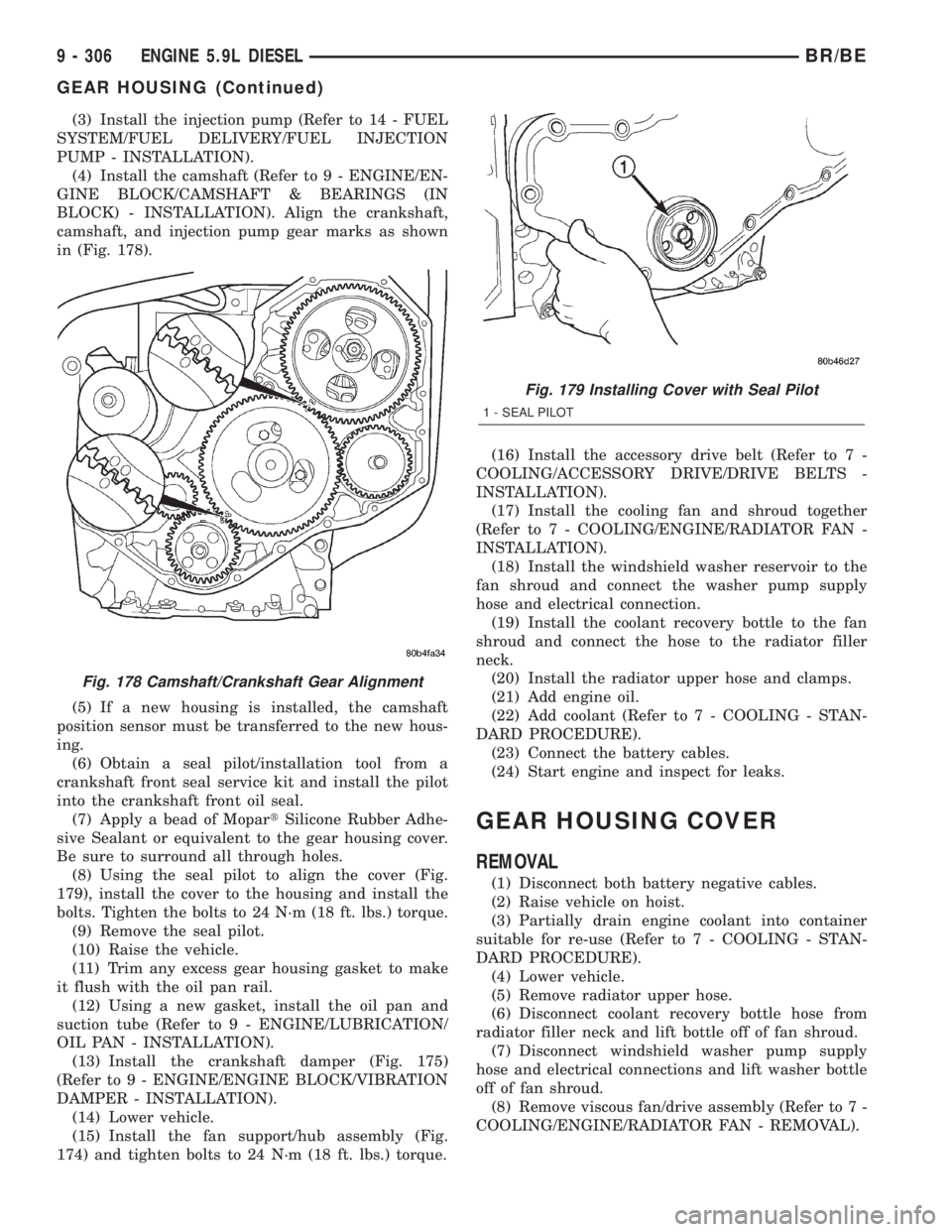
(4) Install the camshaft (Refer to 9 - ENGINE/EN-
GINE BLOCK/CAMSHAFT & BEARINGS (IN
BLOCK) - INSTALLATION). Align the crankshaft,
camshaft, and injection pump gear marks as shown
in (Fig. 178).
(5) If a new housing is installed, the camshaft
position sensor must be transferred to the new hous-
ing.
(6) Obtain a seal pilot/installation tool from a
crankshaft front seal service kit and install the pilot
into the crankshaft front oil seal.
(7) Apply a bead of MopartSilicone Rubber Adhe-
sive Sealant or equivalent to the gear housing cover.
Be sure to surround all through holes.
(8) Using the seal pilot to align the cover (Fig.
179), install the cover to the housing and install the
bolts. Tighten the bolts to 24 N´m (18 ft. lbs.) torque.
(9) Remove the seal pilot.
(10) Raise the vehicle.
(11) Trim any excess gear housing gasket to make
it flush with the oil pan rail.
(12) Using a new gasket, install the oil pan and
suction tube (Refer to 9 - ENGINE/LUBRICATION/
OIL PAN - INSTALLATION).
(13) Install the crankshaft damper (Fig. 175)
(Refer to 9 - ENGINE/ENGINE BLOCK/VIBRATION
DAMPER - INSTALLATION).
(14) Lower vehicle.
(15) Install the fan support/hub assembly (Fig.
174) and tighten bolts to 24 N´m (18 ft. lbs.) torque.(16) Install the accessory drive belt (Refer to 7 -
COOLING/ACCESSORY DRIVE/DRIVE BELTS -
INSTALLATION).
(17) Install the cooling fan and shroud together
(Refer to 7 - COOLING/ENGINE/RADIATOR FAN -
INSTALLATION).
(18) Install the windshield washer reservoir to the
fan shroud and connect the washer pump supply
hose and electrical connection.
(19) Install the coolant recovery bottle to the fan
shroud and connect the hose to the radiator filler
neck.
(20) Install the radiator upper hose and clamps.
(21) Add engine oil.
(22) Add coolant (Refer to 7 - COOLING - STAN-
DARD PROCEDURE).
(23) Connect the battery cables.
(24) Start engine and inspect for leaks.
GEAR HOUSING COVER
REMOVAL
(1) Disconnect both battery negative cables.
(2) Raise vehicle on hoist.
(3) Partially drain engine coolant into container
suitable for re-use (Refer to 7 - COOLING - STAN-
DARD PROCEDURE).
(4) Lower vehicle.
(5) Remove radiator upper hose.
(6) Disconnect coolant recovery bottle hose from
radiator filler neck and lift bottle off of fan shroud.
(7) Disconnect windshield washer pump supply
hose and electrical connections and lift washer bottle
off of fan shroud.
(8) Remove viscous fan/drive assembly (Refer to 7 -
COOLING/ENGINE/RADIATOR FAN - REMOVAL).
Fig. 178 Camshaft/Crankshaft Gear Alignment
Fig. 179 Installing Cover with Seal Pilot
1 - SEAL PILOT
9 - 306 ENGINE 5.9L DIESELBR/BE
GEAR HOUSING (Continued)
Page 1455 of 2889
(8) Install the fan support/hub assy. (Fig. 180) and
tighten bolts to 24 N´m (18 ft. lbs.) torque.
(9) Install the accessory drive belt (Refer to 7 -
COOLING/ACCESSORY DRIVE/DRIVE BELTS -
INSTALLATION).
(10) Install the cooling fan and shroud together
(Refer to 7 - COOLING/ENGINE/RADIATOR FAN -
INSTALLATION).
(11) Install the windshield washer reservoir to the
fan shroud and connect the washer pump supply
hose and electrical connection.(12) Install the coolant recovery bottle to the fan
shroud and connect the hose to the radiator filler
neck.
(13) Install the radiator upper hose and clamps.
(14) Add coolant (Refer to 7 - COOLING - STAN-
DARD PROCEDURE).
(15) Connect the battery cables.
(16) Start engine and inspect for leaks.
9 - 308 ENGINE 5.9L DIESELBR/BE
GEAR HOUSING COVER (Continued)
Page 1472 of 2889
(3)Pre-lube the turbocharger.Pour 50 to 60 cc
(2 to 3 oz.) clean engine oil in the oil supply line fit-
ting. Carefully rotate the turbocharger impeller by
hand to distribute the oil thoroughly.
(4) Install and tighten the oil supply line fitting
nut to 20 N´m (133 in. lbs.) torque.
(5) Position the charge air cooler inlet pipe to the
turbocharger. With the clamp in position, tighten the
clamp nut to 11 N´m (95 in. lbs.) torque.
(6) Position the air inlet hose to the turbocharger
(Fig. 23). Tighten the clamp to 11 N´m (95 in. lbs.)
torque.
(7) Raise vehicle on hoist.
(8) Connect the exhaust pipe to the turbocharger
(Fig. 22) and tighten the bolts to 34 N´m (25 ft. lbs.)
torque.
(9) Lower the vehicle.
(10) Connect the battery negative cables.
(11) Start the engine to check for leaks.
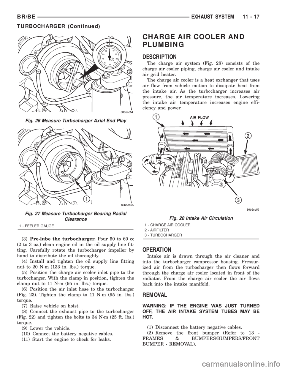
CHARGE AIR COOLER AND
PLUMBING
DESCRIPTION
The charge air system (Fig. 28) consists of the
charge air cooler piping, charge air cooler and intake
air grid heater.
The charge air cooler is a heat exchanger that uses
air flow from vehicle motion to dissipate heat from
the intake air. As the turbocharger increases air
pressure, the air temperature increases. Lowering
the intake air temperature increases engine effi-
ciency and power.
OPERATION
Intake air is drawn through the air cleaner and
into the turbocharger compressor housing. Pressur-
ized air from the turbocharger then flows forward
through the charge air cooler located in front of the
radiator. From the charge air cooler the air flows
back into the intake manifold.
REMOVAL
WARNING: IF THE ENGINE WAS JUST TURNED
OFF, THE AIR INTAKE SYSTEM TUBES MAY BE
HOT.
(1) Disconnect the battery negative cables.
(2) Remove the front bumper (Refer to 13 -
FRAMES & BUMPERS/BUMPERS/FRONT
BUMPER - REMOVAL).
Fig. 26 Measure Turbocharger Axial End Play
Fig. 27 Measure Turbocharger Bearing Radial
Clearance
1 - FEELER GAUGE
Fig. 28 Intake Air Circulation
1 - CHARGE AIR COOLER
2 - AIRFILTER
3 - TURBOCHARGER
BR/BEEXHAUST SYSTEM 11 - 17
TURBOCHARGER (Continued)
Page 1517 of 2889
(11) Inspect accelerator cable, transmission throt-
tle cable (if equipped) and cruise control cable con-
nections (if equipped). Check their connections to the
throttle arm of throttle body for any binding or
restrictions.
(12) If equipped with vacuum brake booster, verify
that vacuum booster hose is firmly connected to fit-
ting on intake manifold. Also check connection to
brake vacuum booster.
(13) Inspect the air cleaner inlet and air cleaner
element for dirt or restrictions.
(14) Inspect radiator grille area, radiator fins and
air conditioning condenser for restrictions.
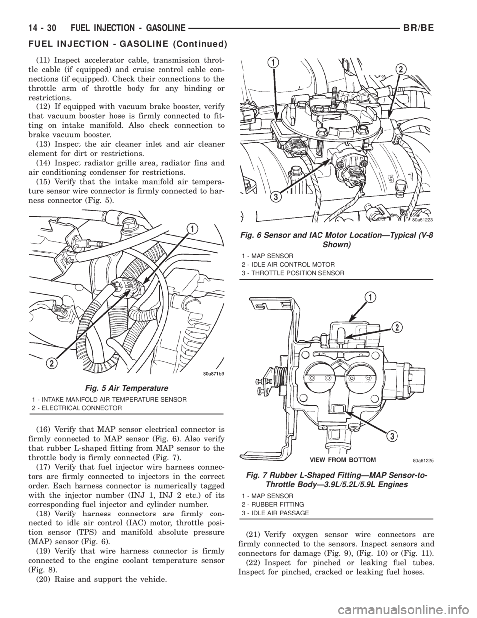
(15) Verify that the intake manifold air tempera-
ture sensor wire connector is firmly connected to har-
ness connector (Fig. 5).
(16) Verify that MAP sensor electrical connector is
firmly connected to MAP sensor (Fig. 6). Also verify
that rubber L-shaped fitting from MAP sensor to the
throttle body is firmly connected (Fig. 7).
(17) Verify that fuel injector wire harness connec-
tors are firmly connected to injectors in the correct
order. Each harness connector is numerically tagged
with the injector number (INJ 1, INJ 2 etc.) of its
corresponding fuel injector and cylinder number.
(18) Verify harness connectors are firmly con-
nected to idle air control (IAC) motor, throttle posi-
tion sensor (TPS) and manifold absolute pressure
(MAP) sensor (Fig. 6).
(19) Verify that wire harness connector is firmly
connected to the engine coolant temperature sensor
(Fig. 8).
(20) Raise and support the vehicle.(21) Verify oxygen sensor wire connectors are
firmly connected to the sensors. Inspect sensors and
connectors for damage (Fig. 9), (Fig. 10) or (Fig. 11).
(22) Inspect for pinched or leaking fuel tubes.
Inspect for pinched, cracked or leaking fuel hoses.
Fig. 5 Air Temperature
1 - INTAKE MANIFOLD AIR TEMPERATURE SENSOR
2 - ELECTRICAL CONNECTOR
Fig. 6 Sensor and IAC Motor LocationÐTypical (V-8
Shown)
1 - MAP SENSOR
2 - IDLE AIR CONTROL MOTOR
3 - THROTTLE POSITION SENSOR
Fig. 7 Rubber L-Shaped FittingÐMAP Sensor-to-
Throttle BodyÐ3.9L/5.2L/5.9L Engines
1 - MAP SENSOR
2 - RUBBER FITTING
3 - IDLE AIR PASSAGE
14 - 30 FUEL INJECTION - GASOLINEBR/BE
FUEL INJECTION - GASOLINE (Continued)
Page 1520 of 2889
(12) If equipped with vacuum brake booster, verify
that vacuum booster hose is firmly connected to fit-
ting on intake manifold. Also check connection to
brake vacuum booster.
(13) Inspect the air cleaner inlet and air cleaner
element for dirt or restrictions.
(14) Inspect radiator grille area, radiator fins and
air conditioning condenser for restrictions.
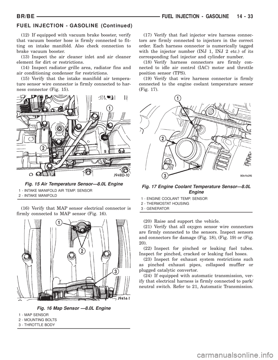
(15) Verify that the intake manifold air tempera-
ture sensor wire connector is firmly connected to har-
ness connector (Fig. 15).
(16) Verify that MAP sensor electrical connector is
firmly connected to MAP sensor (Fig. 16).(17) Verify that fuel injector wire harness connec-
tors are firmly connected to injectors in the correct
order. Each harness connector is numerically tagged
with the injector number (INJ 1, INJ 2 etc.) of its
corresponding fuel injector and cylinder number.
(18) Verify harness connectors are firmly con-
nected to idle air control (IAC) motor and throttle
position sensor (TPS).
(19) Verify that wire harness connector is firmly
connected to the engine coolant temperature sensor
(Fig. 17).
(20) Raise and support the vehicle.
(21) Verify that all oxygen sensor wire connectors
are firmly connected to the sensors. Inspect sensors
and connectors for damage (Fig. 18), (Fig. 19) or (Fig.
20).
(22) Inspect for pinched or leaking fuel tubes.
Inspect for pinched, cracked or leaking fuel hoses.
(23) Inspect for exhaust system restrictions such
as pinched exhaust pipes, collapsed muffler or
plugged catalytic convertor.
(24) If equipped with automatic transmission, ver-
ify that electrical harness is firmly connected to park/
neutral switch. Refer to 21, Automatic Transmission.
Fig. 15 Air Temperature SensorÐ8.0L Engine
1 - INTAKE MANIFOLD AIR TEMP. SENSOR
2 - INTAKE MANIFOLD
Fig. 16 Map Sensor Ð8.0L Engine
1 - MAP SENSOR
2 - MOUNTING BOLTS
3 - THROTTLE BODY
Fig. 17 Engine Coolant Temperature SensorÐ8.0L
Engine
1 - ENGINE COOLANT TEMP. SENSOR
2 - THERMOSTAT HOUSING
3 - GENERATOR
BR/BEFUEL INJECTION - GASOLINE 14 - 33
FUEL INJECTION - GASOLINE (Continued)
Page 1537 of 2889
(5) Install control cables.
(6) Install electrical connectors.
(7) Install air cleaner housing to throttle body.
(8) Install 4 air cleaner housing mounting nuts.
Tighten nuts to 11 N´m (96 in. lbs.) torque.
(9) Install air cleaner housing cover.
THROTTLE CONTROL CABLE
REMOVAL
CAUTION: Be careful not to damage or kink the
cable core wire (within the cable sheathing) while
servicing accelerator pedal or cables.
(1) From inside the vehicle, hold up the accelerator
pedal. Remove the plastic cable retainer and throttle
cable core wire from upper end of pedal arm (Fig.
21). The plastic cable retainer snaps into pedal the
arm.
(2) Remove the cable core wire at the pedal arm.
(3) Remove the air cleaner housing.
(4) From inside the vehicle, pinch both sides of the
plastic cable housing retainer tabs at the dash panel
(Fig. 21).
(5) Remove cable housing from dash panel and
pull the cable into the engine compartment.
(6)3.9L/5.2L/5.9L Engines:Disconnect the cable
from the routing/holddown clip at the radiator fan
shroud.
(7)8.0L V-10 Engine:Remove the throttle cable
socket at throttle lever ball. (Fig. 45) (snaps off).
(8)3.9L/5.2L/5.9L Engines:Slip the cable end
rearward from pin on throttle body (Fig. 44).
(9) Remove cable housing at throttle body mount-
ing bracket by pressing on release tab with a small
screwdriver (Fig. 46) or (Fig. 45).To prevent cable
housing breakage, press on the tab only enough
to release the cable from the bracket.Lift the
cable housing straight up from bracket while press-
ing on release tab. Remove throttle cable from vehi-
cle.
INSTALLATION
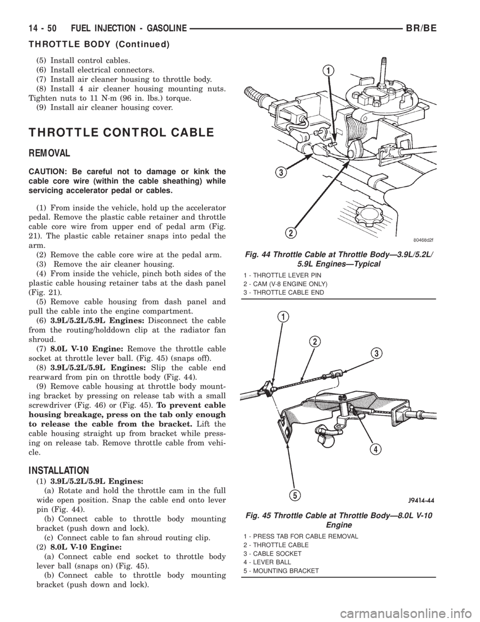
(1)3.9L/5.2L/5.9L Engines:
(a) Rotate and hold the throttle cam in the full
wide open position. Snap the cable end onto lever
pin (Fig. 44).
(b) Connect cable to throttle body mounting
bracket (push down and lock).
(c) Connect cable to fan shroud routing clip.
(2)8.0L V-10 Engine:
(a) Connect cable end socket to throttle body
lever ball (snaps on) (Fig. 45).
(b) Connect cable to throttle body mounting
bracket (push down and lock).
Fig. 44 Throttle Cable at Throttle BodyÐ3.9L/5.2L/
5.9L EnginesÐTypical
1 - THROTTLE LEVER PIN
2 - CAM (V-8 ENGINE ONLY)
3 - THROTTLE CABLE END
Fig. 45 Throttle Cable at Throttle BodyÐ8.0L V-10
Engine
1 - PRESS TAB FOR CABLE REMOVAL
2 - THROTTLE CABLE
3 - CABLE SOCKET
4 - LEVER BALL
5 - MOUNTING BRACKET
14 - 50 FUEL INJECTION - GASOLINEBR/BE
THROTTLE BODY (Continued)
Page 1834 of 2889
FLUID AND FILTER
DIAGNOSIS AND TESTING - EFFECTS OF
INCORRECT FLUID LEVEL
A low fluid level allows the pump to take in air
along with the fluid. Air in the fluid will cause fluid
pressures to be low and develop slower than normal.
If the transmission is overfilled, the gears churn the
fluid into foam. This aerates the fluid and causing
the same conditions occurring with a low level. In
either case, air bubbles cause fluid overheating, oxi-
dation and varnish buildup which interferes with
valve and clutch operation. Foaming also causes fluid
expansion which can result in fluid overflow from the
transmission vent or fill tube. Fluid overflow can eas-
ily be mistaken for a leak if inspection is not careful.
DIAGNOSIS AND TESTING - CAUSES OF
BURNT FLUID
Burnt, discolored fluid is a result of overheating
which has two primary causes.
(1) A result of restricted fluid flow through the
main and/or auxiliary cooler. This condition is usu-
ally the result of a faulty or improperly installed
drainback valve, a damaged main cooler, or severe
restrictions in the coolers and lines caused by debris
or kinked lines.
(2) Heavy duty operation with a vehicle not prop-
erly equipped for this type of operation. Trailer tow-
ing or similar high load operation will overheat the
transmission fluid if the vehicle is improperly
equipped. Such vehicles should have an auxiliary
transmission fluid cooler, a heavy duty cooling sys-
tem, and the engine/axle ratio combination needed to
handle heavy loads.
DIAGNOSIS AND TESTING - FLUID
CONTAMINATION
Transmission fluid contamination is generally a
result of:
²adding incorrect fluid
²failure to clean dipstick and fill tube when
checking level
²engine coolant entering the fluid
²internal failure that generates debris
²
overheat that generates sludge (fluid breakdown)
²failure to reverse flush cooler and lines after repair
²failure to replace contaminated converter after
repair
The use of non-recommended fluids can result in
transmission failure. The usual results are erratic
shifts, slippage, abnormal wear and eventual failure
due to fluid breakdown and sludge formation. Avoid
this condition by using recommended fluids only.
The dipstick cap and fill tube should be wiped clean
before checking fluid level. Dirt, grease and other for-
eign material on the cap and tube could fall into the
tube if not removed beforehand. Take the time to wipe
the cap and tube clean before withdrawing the dipstick.
Engine coolant in the transmission fluid is gener-
ally caused by a cooler malfunction. The only remedy
is to replace the radiator as the cooler in the radiator
is not a serviceable part. If coolant has circulated
through the transmission, an overhaul is necessary.
The transmission cooler and lines should be
reverse flushed whenever a malfunction generates
sludge and/or debris. The torque converter should
also be replaced at the same time.
Failure to flush the cooler and lines will result in
recontamination. Flushing applies to auxiliary coolers
as well. The torque converter should also be replaced
whenever a failure generates sludge and debris. This is
necessary because normal converter flushing procedures
will not remove all contaminants.
STANDARD PROCEDURE - FLUID LEVEL
CHECK
Low fluid level can cause a variety of conditions
because it allows the pump to take in air along with
the fluid. As in any hydraulic system, air bubbles
make the fluid spongy, therefore, pressures will be
low and build up slowly.
Improper filling can also raise the fluid level too
high. When the transmssion has too much fluid, the
geartrain churns up foam and cause the same condi-
tions which occur with a low fluid level.
In either case, air bubbles can cause overheating
and/or fluid oxidation, and varnishing. This can inter-
fere with normal valve, clutch, and accumulator opera-
tion. Foaming can also result in fluid escaping from the
transmission vent where it may be mistaken for a leak.
Along with fluid level, it is important to check the
condition of the fluid. When the fluid smells burned,
and is contaminated with metal or friction material
particles, a complete transmission recondition is
needed. Be sure to examine the fluid on the dipstick
closely. If there is any doubt about its condition,
drain out a sample for a double check.
After the fluid has been checked, seat the dipstick
fully to seal out water and dirt.
The transmission has a dipstick to check oil level.
It is located on the right side of the engine. Be sure
to wipe all dirt from dipstick handle before removing.
Fluid level is checked with the engine running at curb
idle speed, the transmission in NEUTRAL and the trans-
mission fluid at normal operating temperature.The
engine should be running at idle speed for at least
one minute, with the vehicle on level ground.
The transmission fluid level can be checked two
ways.
BR/BEAUTOMATIC TRANSMISSION - 42RE 21 - 199