2001 DODGE RAM radiator
[x] Cancel search: radiatorPage 2667 of 2889
(15) Install air cleaner (DIESEL ONLY).
(16) Install front bumper (Refer to 13 - FRAMES
& BUMPERS/BUMPERS/FRONT BUMPER -
INSTALLATION).
RIGHT FRONT FENDER
REMOVAL
(1) Remove front bumper (Refer to 13 - FRAMES
& BUMPERS/BUMPERS/FRONT BUMPER -
REMOVAL).
(2) Disconnect and isolate battery negative cable.
(3) Remove auxiliary battery and tray on right
side, if equipped.
(4) Disengage wire harness tie-downs from wheel-
house.
(5) Disconnect wiring harness to headlamp connec-
tor.
(6) Disconnect wiring harness to airbag sensor and
remove airbag sensor from wheelhouse.
(7) Remove front wheelhouse liner (Fig. 13) (Refer
to 23 - BODY/EXTERIOR/FRONT END SPLASH
SHIELDS - REMOVAL).
(8) Disengage air conditioning tubing from inner
fender clips.
(9) Remove bolts attaching front fender to cowl
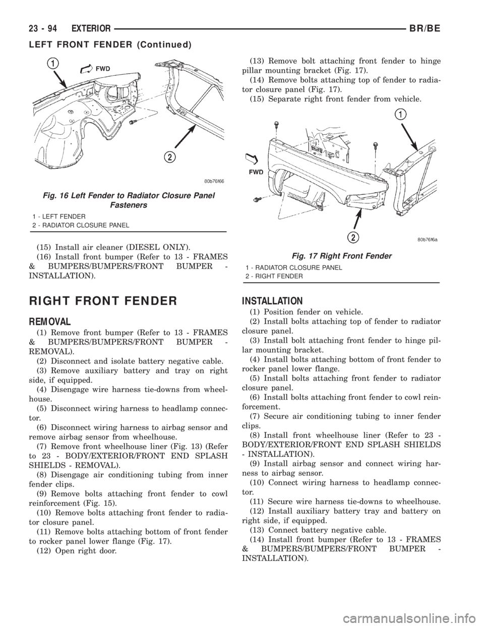
reinforcement (Fig. 15).
(10) Remove bolts attaching front fender to radia-
tor closure panel.
(11) Remove bolts attaching bottom of front fender
to rocker panel lower flange (Fig. 17).
(12) Open right door.(13) Remove bolt attaching front fender to hinge
pillar mounting bracket (Fig. 17).
(14) Remove bolts attaching top of fender to radia-
tor closure panel (Fig. 17).
(15) Separate right front fender from vehicle.
INSTALLATION
(1) Position fender on vehicle.
(2) Install bolts attaching top of fender to radiator
closure panel.
(3) Install bolt attaching front fender to hinge pil-
lar mounting bracket.
(4) Install bolts attaching bottom of front fender to
rocker panel lower flange.
(5) Install bolts attaching front fender to radiator
closure panel.
(6) Install bolts attaching front fender to cowl rein-
forcement.
(7) Secure air conditioning tubing to inner fender
clips.
(8) Install front wheelhouse liner (Refer to 23 -
BODY/EXTERIOR/FRONT END SPLASH SHIELDS
- INSTALLATION).
(9) Install airbag sensor and connect wiring har-
ness to airbag sensor.
(10) Connect wiring harness to headlamp connec-
tor.
(11) Secure wire harness tie-downs to wheelhouse.
(12) Install auxiliary battery tray and battery on
right side, if equipped.
(13) Connect battery negative cable.
(14) Install front bumper (Refer to 13 - FRAMES
& BUMPERS/BUMPERS/FRONT BUMPER -
INSTALLATION).
Fig. 16 Left Fender to Radiator Closure Panel
Fasteners
1 - LEFT FENDER
2 - RADIATOR CLOSURE PANEL
Fig. 17 Right Front Fender
1 - RADIATOR CLOSURE PANEL
2 - RIGHT FENDER
23 - 94 EXTERIORBR/BE
LEFT FRONT FENDER (Continued)
Page 2673 of 2889
HOOD
REMOVAL
(1) Disconnect the under hood lamp wire connec-
tor.
(2) Disconnect the air temperature sensor wire
connector, if equipped.
(3) Mark all bolt and hinge attachment locations
with a grease pencil or equivalent to provide refer-
ence marks for installation.
(4) Remove top nuts attaching hood to hinge and
loosen bottom nuts until they can be removed by
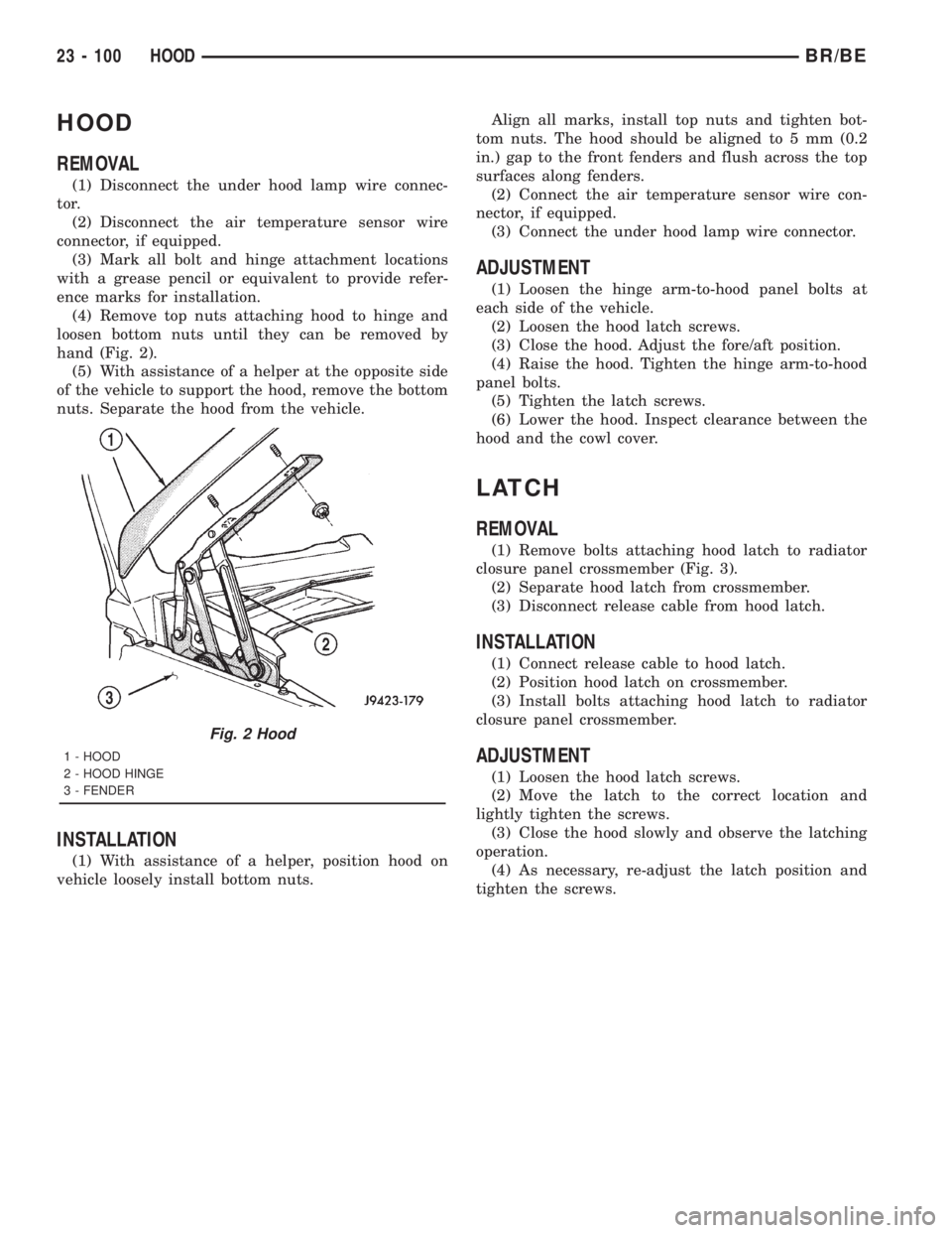
hand (Fig. 2).
(5) With assistance of a helper at the opposite side
of the vehicle to support the hood, remove the bottom
nuts. Separate the hood from the vehicle.
INSTALLATION
(1) With assistance of a helper, position hood on
vehicle loosely install bottom nuts.Align all marks, install top nuts and tighten bot-
tom nuts. The hood should be aligned to 5 mm (0.2
in.) gap to the front fenders and flush across the top
surfaces along fenders.
(2) Connect the air temperature sensor wire con-
nector, if equipped.
(3) Connect the under hood lamp wire connector.
ADJUSTMENT
(1) Loosen the hinge arm-to-hood panel bolts at
each side of the vehicle.
(2) Loosen the hood latch screws.
(3) Close the hood. Adjust the fore/aft position.
(4) Raise the hood. Tighten the hinge arm-to-hood
panel bolts.
(5) Tighten the latch screws.
(6) Lower the hood. Inspect clearance between the
hood and the cowl cover.
LATCH
REMOVAL
(1) Remove bolts attaching hood latch to radiator
closure panel crossmember (Fig. 3).
(2) Separate hood latch from crossmember.
(3) Disconnect release cable from hood latch.
INSTALLATION
(1) Connect release cable to hood latch.
(2) Position hood latch on crossmember.
(3) Install bolts attaching hood latch to radiator
closure panel crossmember.
ADJUSTMENT
(1) Loosen the hood latch screws.
(2) Move the latch to the correct location and
lightly tighten the screws.
(3) Close the hood slowly and observe the latching
operation.
(4) As necessary, re-adjust the latch position and
tighten the screws.
Fig. 2 Hood
1 - HOOD
2 - HOOD HINGE
3 - FENDER
23 - 100 HOODBR/BE
Page 2702 of 2889
PAINT
TABLE OF CONTENTS
page page
PAINT
SPECIFICATIONS........................129
BASE COAT/CLEAR COAT FINISH
DESCRIPTION..........................129
OPERATION............................129
PAINT CODE
DESCRIPTION..........................129PAINT TOUCH-UP
DESCRIPTION..........................129
WET SANDING/BUFFING & POLISHING
DESCRIPTION..........................130
PAINT
SPECIFICATIONS
2001 BR PAINT COLOR CODES
EXTERIOR COLORS
DC
CODEEXTERIOR
COLORDC
CODEEXTERIOR
COLOR
DX8Black Clear
CoatGW7Bright White
Clear Coat
PR4Flame Red
Clear CoatVB3Intense Blue
Pearl Coat
WBT/
WB7Patriot Blue
Pearl CoatSG8Forest Green
Pearl Coat
XV3/XVLAmber Fire
Pearl CoatWSB/
WS2Bright Silver
Metallic
Clear Coat
XTLSierra
BronzeXRVDark Garnet
Red
INTERIOR COLORS
DC
CODEINTERIOR
COLORDC
CODEINTERIOR
COLOR
A Agate M Mist Gray
C Camel
BASE COAT/CLEAR COAT
FINISH
DESCRIPTION
The original equipment finish is a multi-step pro-
cess that involves cleaning, electrodeposition (e-coat),
base coat, and clear coat steps. Additionally, selectedareas of the vehicle may be coated with an anti-chip
finish.
OPERATION
On most vehicles a two-part paint application (base
coat/clear coat) is used. Color paint that is applied to
primer is called base coat. The clear coat protects the
base coat from ultraviolet light and provides a dura-
ble high-gloss finish.
CAUTION: Do not use abrasive chemicals or com-
pounds on painted surfaces. Damage to finish can
result.
Do not use harsh alkaline based cleaning solvents
on painted surfaces. Damage to finish or color can
result.
PAINT CODE
DESCRIPTION
Exterior vehicle body colors are identified on the
Body Code plate. The plate is located on the floor pan
under the passenger seat or attached to the front
face of the radiator closure panel. Refer to the Intro-
duction section at the front of this manual for body
code plate description. The paint code is also identi-
fied on the Vehicle Safety Certification Label which
is located on the drivers door shut face. The color
names provided in the Paint and Trim Code Descrip-
tion chart are the color names used on most repair
product containers.
PAINT TOUCH-UP
DESCRIPTION
When a painted metal surface has been scratched
or chipped, it should be touched-up as soon as possi-
ble to avoid corrosion. For best results, use Moparž
BR/BEPAINT 23 - 129
Page 2730 of 2889
HEATING & AIR CONDITIONING
TABLE OF CONTENTS
page page
HEATING & AIR CONDITIONING
DESCRIPTION............................1
OPERATION.............................1
DIAGNOSIS AND TESTING..................2
A/C PERFORMANCE.....................2
HEATER PERFORMANCE.................6STANDARD PROCEDURE...................7
DIODE REPLACEMENT...................7
SPECIFICATIONS.........................8
CONTROLS..............................9
DISTRIBUTION..........................31
PLUMBING.............................40
HEATING & AIR
CONDITIONING
DESCRIPTION - HEATER AND AIR
CONDITIONER
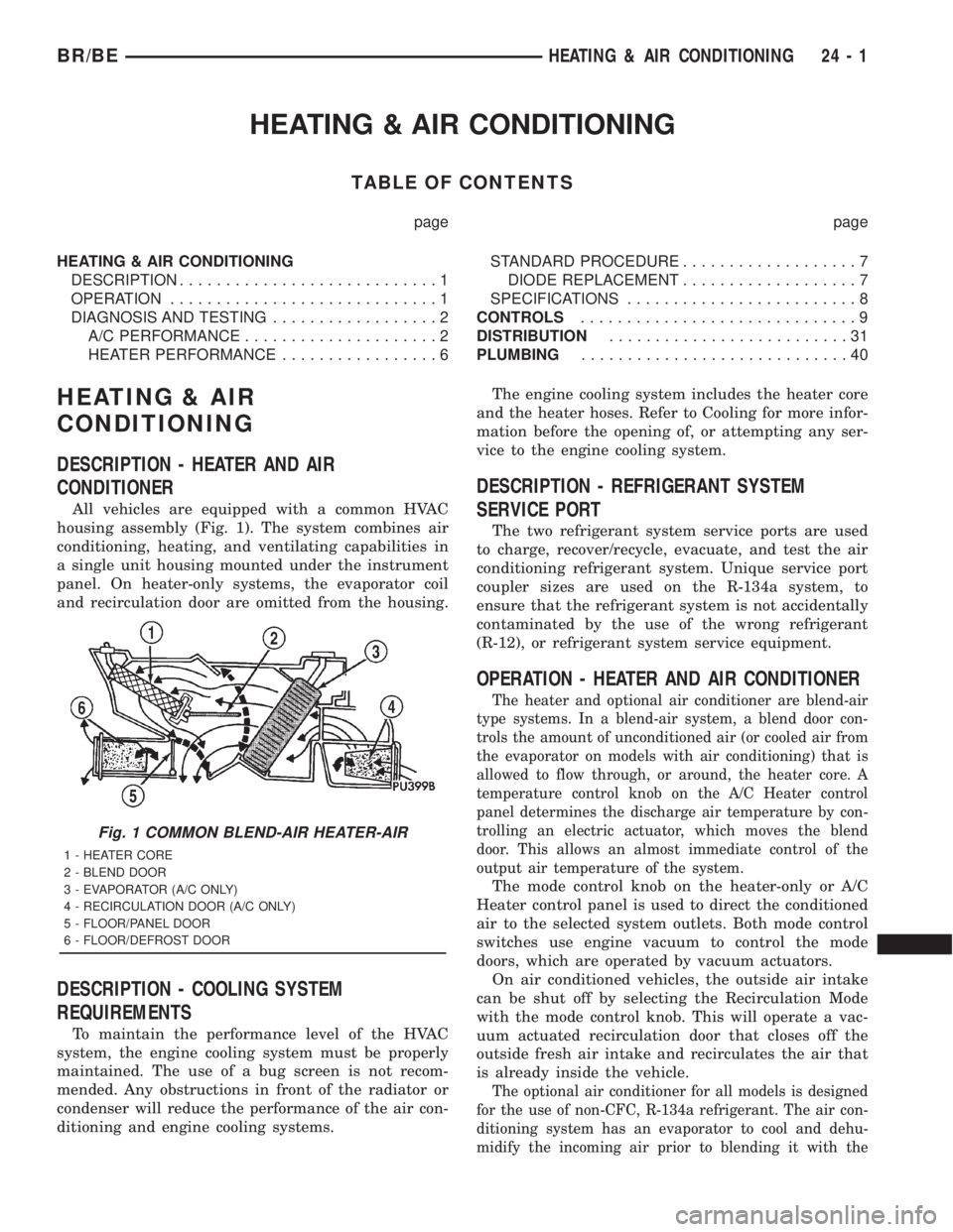
All vehicles are equipped with a common HVAC
housing assembly (Fig. 1). The system combines air
conditioning, heating, and ventilating capabilities in
a single unit housing mounted under the instrument
panel. On heater-only systems, the evaporator coil
and recirculation door are omitted from the housing.
DESCRIPTION - COOLING SYSTEM
REQUIREMENTS
To maintain the performance level of the HVAC
system, the engine cooling system must be properly
maintained. The use of a bug screen is not recom-
mended. Any obstructions in front of the radiator or
condenser will reduce the performance of the air con-
ditioning and engine cooling systems.The engine cooling system includes the heater core
and the heater hoses. Refer to Cooling for more infor-
mation before the opening of, or attempting any ser-
vice to the engine cooling system.
DESCRIPTION - REFRIGERANT SYSTEM
SERVICE PORT
The two refrigerant system service ports are used
to charge, recover/recycle, evacuate, and test the air
conditioning refrigerant system. Unique service port
coupler sizes are used on the R-134a system, to
ensure that the refrigerant system is not accidentally
contaminated by the use of the wrong refrigerant
(R-12), or refrigerant system service equipment.
OPERATION - HEATER AND AIR CONDITIONER
The heater and optional air conditioner are blend-air
type systems. In a blend-air system, a blend door con-
trols the amount of unconditioned air (or cooled air from
the evaporator on models with air conditioning) that is
allowed to flow through, or around, the heater core. A
temperature control knob on the A/C Heater control
panel determines the discharge air temperature by con-
trolling an electric actuator, which moves the blend
door. This allows an almost immediate control of the
output air temperature of the system.
The mode control knob on the heater-only or A/C
Heater control panel is used to direct the conditioned
air to the selected system outlets. Both mode control
switches use engine vacuum to control the mode
doors, which are operated by vacuum actuators.
On air conditioned vehicles, the outside air intake
can be shut off by selecting the Recirculation Mode
with the mode control knob. This will operate a vac-
uum actuated recirculation door that closes off the
outside fresh air intake and recirculates the air that
is already inside the vehicle.
The optional air conditioner for all models is designed
for the use of non-CFC, R-134a refrigerant. The air con-
ditioning system has an evaporator to cool and dehu-
midify the incoming air prior to blending it with the
Fig. 1 COMMON BLEND-AIR HEATER-AIR
1 - HEATER CORE
2 - BLEND DOOR
3 - EVAPORATOR (A/C ONLY)
4 - RECIRCULATION DOOR (A/C ONLY)
5 - FLOOR/PANEL DOOR
6 - FLOOR/DEFROST DOOR
BR/BEHEATING & AIR CONDITIONING 24 - 1
Page 2735 of 2889
DIAGNOSIS AND TESTING - HEATER
PERFORMANCE
Before performing the following tests, refer to Cool-
ing for the procedures to check the engine coolant
level and flow, engine coolant reserve/recovery sys-
tem operation, accessory drive belt condition and ten-
sion, radiator air flow and the fan drive operation.
Also be certain that the accessory vacuum supply
line is connected at the engine vacuum source.
MAXIMUM HEATER OUTPUT
Engine coolant is delivered to the heater core
through two heater hoses. With the engine idling atnormal operating temperature, set the temperature
control knob in the full hot position, the mode control
switch knob in the floor position, and the blower
motor switch knob in the highest speed position.
Using a test thermometer, check the temperature of
the air being discharged at the HVAC housing floor
outlets. Compare the test thermometer reading to the
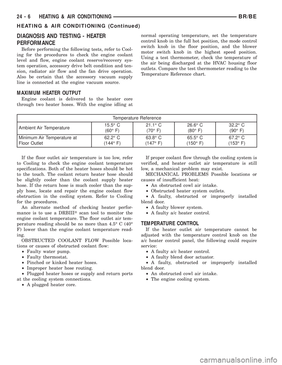
Temperature Reference chart.
Temperature Reference
Ambient Air Temperature15.5É C
(60É F)21.1É C
(70É F)26.6É C
(80É F)32.2É C
(90É F)
Minimum Air Temperature at
Floor Outlet62.2É C
(144É F)63.8É C
(147É F)65.5É C
(150É F)67.2É C
(153É F)
If the floor outlet air temperature is too low, refer
to Cooling to check the engine coolant temperature
specifications. Both of the heater hoses should be hot
to the touch. The coolant return heater hose should
be slightly cooler than the coolant supply heater
hose. If the return hose is much cooler than the sup-
ply hose, locate and repair the engine coolant flow
obstruction in the cooling system. Refer to Cooling
for the procedures.
An alternate method of checking heater perfor-
mance is to use a DRBIIItscan tool to monitor the
engine coolant temperature. The floor outlet air tem-
perature reading should be no more than 4.5É C (40É
F) lower than the engine coolant temperature read-
ing.
OBSTRUCTED COOLANT FLOW Possible loca-
tions or causes of obstructed coolant flow:
²Faulty water pump.
²Faulty thermostat.
²Pinched or kinked heater hoses.
²Improper heater hose routing.
²Plugged heater hoses or supply and return ports
at the cooling system connections.
²A plugged heater core.If proper coolant flow through the cooling system is
verified, and heater outlet air temperature is still
low, a mechanical problem may exist.
MECHANICAL PROBLEMS Possible locations or
causes of insufficient heat:
²An obstructed cowl air intake.
²Obstructed heater system outlets.
²A faulty, obstructed or improperly installed
blend door.
²A faulty blower system.
²A faulty a/c heater control.
TEMPERATURE CONTROL
If the heater outlet air temperature cannot be
adjusted with the temperature control knob on the
a/c heater control panel, the following could require
service:
²A faulty a/c heater control.
²A faulty blend door actuator.
²A faulty, obstructed or improperly installed
blend door.
²An obstructed cowl air intake.
²The engine cooling system.
24 - 6 HEATING & AIR CONDITIONINGBR/BE
HEATING & AIR CONDITIONING (Continued)
Page 2736 of 2889
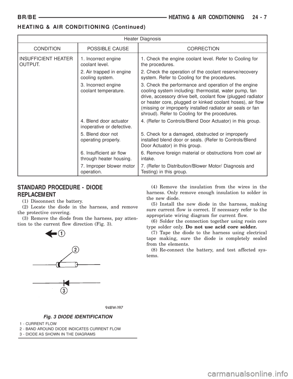
Heater Diagnosis
CONDITION POSSIBLE CAUSE CORRECTION
INSUFFICIENT HEATER
OUTPUT.1. Incorrect engine
coolant level.1. Check the engine coolant level. Refer to Cooling for
the procedures.
2. Air trapped in engine
cooling system.2. Check the operation of the coolant reserve/recovery
system. Refer to Cooling for the procedures.
3. Incorrect engine
coolant temperature.3. Check the performance and operation of the engine
cooling system including: thermostat, water pump, fan
drive, accessory drive belt, coolant flow (plugged radiator
or heater core, plugged or kinked coolant hoses), air flow
(missing or improperly installed radiator air seals or fan
shroud). Refer to Cooling for the procedures.
4. Blend door actuator
inoperative or defective.4. (Refer to Controls/Blend Door Actuator) in this group.
5. Blend door not
operating properly.5. Check for a damaged, obstructed or improperly
installed blend door or seals. (Refer to Controls/Blend
Door Actuator) in this group.
6. Insufficient air flow
through heater housing.6. Remove foreign material or obstructions from cowl air
intake.
7. Improper blower motor
operation.7. (Refer to Distribution/Blower Motor/ Diagnosis and
Testing) in this group.
STANDARD PROCEDURE - DIODE
REPLACEMENT
(1) Disconnect the battery.
(2) Locate the diode in the harness, and remove
the protective covering.
(3) Remove the diode from the harness, pay atten-
tion to the current flow direction (Fig. 3).(4) Remove the insulation from the wires in the
harness. Only remove enough insulation to solder in
the new diode.
(5) Install the new diode in the harness, making
sure current flow is correct. If necessary refer to the
appropriate wiring diagram for current flow.
(6) Solder the connection together using rosin core
type solder only.Do not use acid core solder.
(7) Tape the diode to the harness using electrical
tape making, sure the diode is completely sealed
from the elements.
(8) Re-connect the battery, and test affected sys-
tems.
Fig. 3 DIODE IDENTIFICATION
1 - CURRENT FLOW
2 - BAND AROUND DIODE INDICATES CURRENT FLOW
3 - DIODE AS SHOWN IN THE DIAGRAMS
BR/BEHEATING & AIR CONDITIONING 24 - 7
HEATING & AIR CONDITIONING (Continued)
Page 2777 of 2889
(3) Install the serpentine drive belt. Refer to Cool-
ing for the procedures.
(4) Plug in the compressor clutch coil wire harness
connector.
(5) Connect the battery negative cable.
(6) Evacuate the refrigerant system. (Refer to 24 -
HEATING & AIR CONDITIONING/PLUMBING -
STANDARD PROCEDURE - REFRIGERANT SYS-
TEM EVACUATE)
(7) Charge the refrigerant system. (Refer to 24 -
HEATING & AIR CONDITIONING/PLUMBING -
STANDARD PROCEDURE - REFRIGERANT SYS-
TEM CHARGE)
A/C CONDENSER
DESCRIPTION
The condenser is located in the air flow in front of
the engine cooling radiator. The condenser is a heat
exchanger that allows the high-pressure refrigerant
gas being discharged by the compressor to give up itsheat to the air passing over the condenser fins, thus
causing the refrigerant to change to a liquid state.
OPERATION
When the refrigerant gas gives up its heat, it con-
denses. When the refrigerant leaves the condenser, it
has become a high-pressure liquid refrigerant. The
volume of air flowing over the condenser fins is crit-
ical to the proper cooling performance of the air con-
ditioning system. Therefore, it is important that
there are no objects placed in front of the radiator
grille openings in the front of the vehicle or foreign
material on the condenser fins that might obstruct
proper air flow. Also, any factory-installed air seals or
shrouds must be properly reinstalled following radia-
tor or condenser service.
The condenser cannot be repaired and, if faulty or
damaged, it must be replaced.
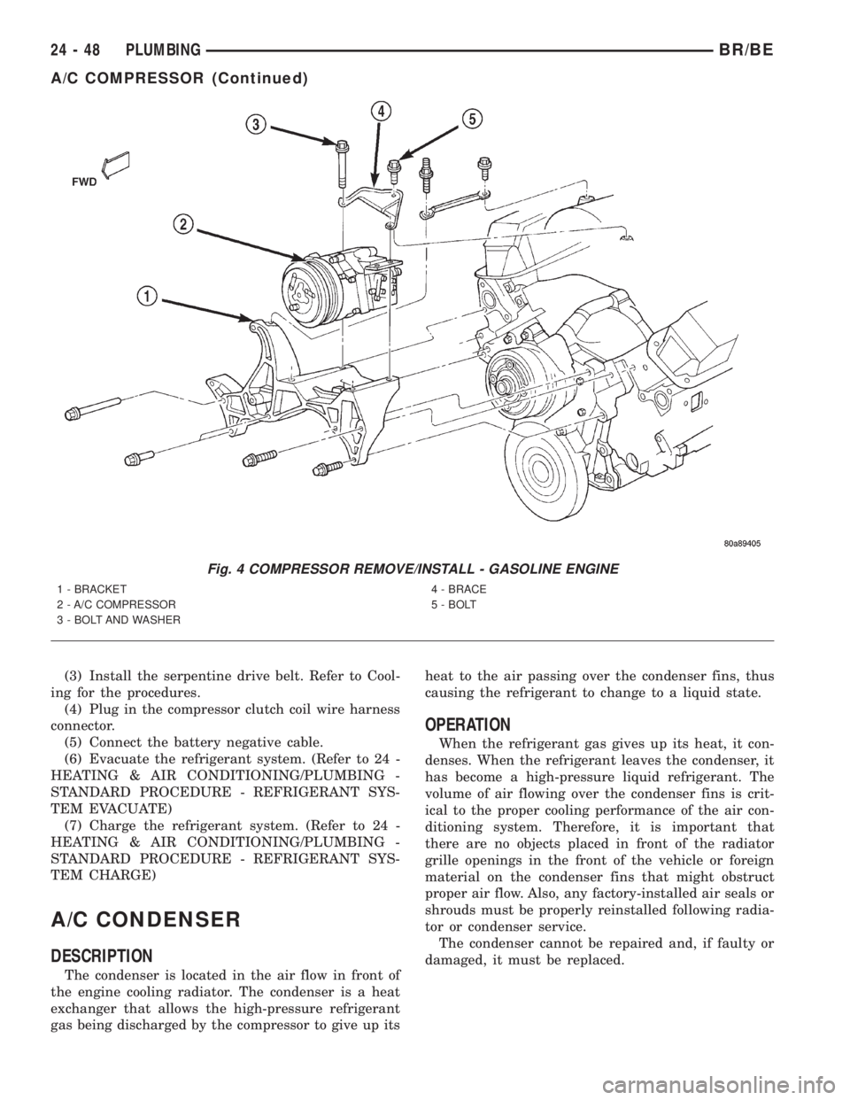
Fig. 4 COMPRESSOR REMOVE/INSTALL - GASOLINE ENGINE
1 - BRACKET
2 - A/C COMPRESSOR
3 - BOLT AND WASHER4 - BRACE
5 - BOLT
24 - 48 PLUMBINGBR/BE
A/C COMPRESSOR (Continued)
Page 2778 of 2889
REMOVAL
WARNING: REVIEW THE WARNINGS AND CAU-
TIONS IN THE FRONT OF THIS SECTION BEFORE
PERFORMING THE FOLLOWING OPERATION.
(Refer to 24 - HEATING & AIR CONDITIONING/
PLUMBING - WARNING) (Refer to 24 - HEATING &
AIR CONDITIONING/PLUMBING - CAUTION)
(1) Disconnect and isolate the battery negative
cable.
(2) Recover the refrigerant from the refrigerant
system. (Refer to 24 - HEATING & AIR CONDI-
TIONING/PLUMBING - STANDARD PROCEDURE -
REFRIGERANT RECOVERY)
(3) Remove the nut that secures the block fitting
to the stud on the condenser inlet, and disconnect the
discharge line from the condenser. Install plugs in, or
tape over all of the opened refrigerant line fittings.
(4) Disconnect the refrigerant line fitting that
secures the liquid line to the condenser outlet. (Refer
to 24 - HEATING & AIR CONDITIONING/PLUMB-
ING - STANDARD PROCEDURE - A/C LINE COU-
PLER) Install plugs in, or tape over all of the opened
refrigerant line fittings.
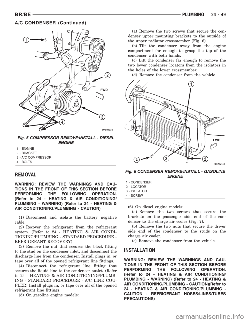
(5) On gasoline engine models:(a) Remove the two screws that secure the con-
denser upper mounting brackets to the outside of
the upper radiator crossmember (Fig. 6).
(b) Tilt the condenser away from the engine
compartment far enough to grasp the top of the
condenser with both hands.
(c) Lift the condenser far enough to remove the
two lower condenser locators from the isolators in
the holes of the lower crossmember.
(d) Remove the condenser from the vehicle.
(6) On diesel engine models:
(a) Remove the two screws that secure the
brackets on the passenger side end of the con-
denser to the charge air cooler (Fig. 7).
(b) Remove the two nuts that secure the driver
side end of the condenser to the studs on the
charge air cooler.
(c) Remove the condenser from the vehicle.
INSTALLATION
WARNING: REVIEW THE WARNINGS AND CAU-
TIONS IN THE FRONT OF THIS SECTION BEFORE
PERFORMING THE FOLLOWING OPERATION.
(Refer to 24 - HEATING & AIR CONDITIONING/
PLUMBING - WARNING) (Refer to 24 - HEATING &
AIR CONDITIONING/PLUMBING - CAUTION)(Refer to
24 - HEATING & AIR CONDITIONING/PLUMBING -
CAUTION - REFRIGERANT HOSES/LINES/TUBES
PRECAUTIONS)
Fig. 5 COMPRESSOR REMOVE/INSTALL - DIESEL
ENGINE
1 - ENGINE
2 - BRACKET
3 - A/C COMPRESSOR
4 - BOLTS
Fig. 6 CONDENSER REMOVE/INSTALL - GASOLINE
ENGINE
1 - CONDENSER
2 - LOCATOR
3 - ISOLATOR
4 - SCREW
BR/BEPLUMBING 24 - 49
A/C CONDENSER (Continued)