2001 DODGE RAM intake manifold
[x] Cancel search: intake manifoldPage 1314 of 2889
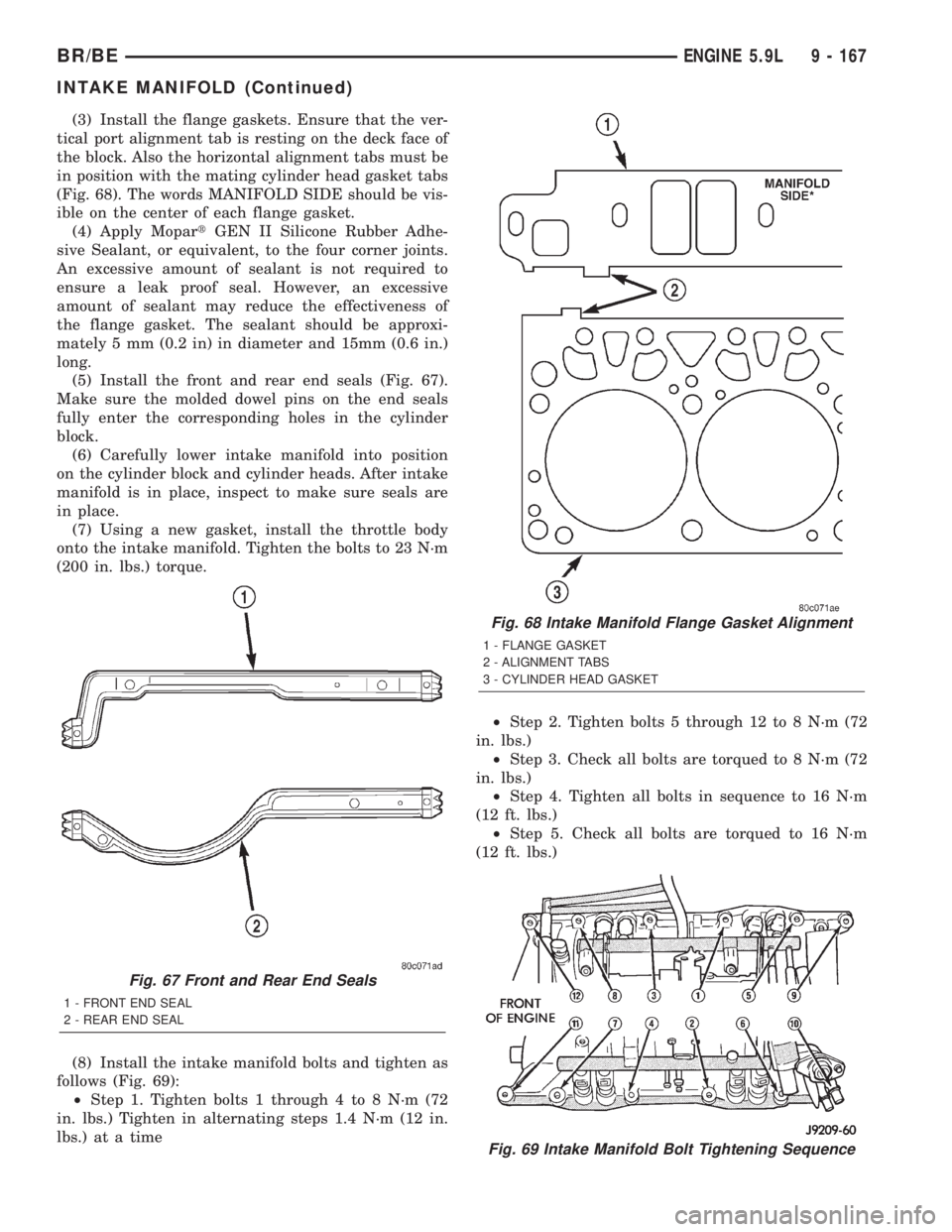
(3) Install the flange gaskets. Ensure that the ver-
tical port alignment tab is resting on the deck face of
the block. Also the horizontal alignment tabs must be
in position with the mating cylinder head gasket tabs
(Fig. 68). The words MANIFOLD SIDE should be vis-
ible on the center of each flange gasket.
(4) Apply MopartGEN II Silicone Rubber Adhe-
sive Sealant, or equivalent, to the four corner joints.
An excessive amount of sealant is not required to
ensure a leak proof seal. However, an excessive
amount of sealant may reduce the effectiveness of
the flange gasket. The sealant should be approxi-
mately 5 mm (0.2 in) in diameter and 15mm (0.6 in.)
long.
(5) Install the front and rear end seals (Fig. 67).
Make sure the molded dowel pins on the end seals
fully enter the corresponding holes in the cylinder
block.
(6) Carefully lower intake manifold into position
on the cylinder block and cylinder heads. After intake
manifold is in place, inspect to make sure seals are
in place.
(7) Using a new gasket, install the throttle body
onto the intake manifold. Tighten the bolts to 23 N´m
(200 in. lbs.) torque.
(8) Install the intake manifold bolts and tighten as
follows (Fig. 69):
²Step 1. Tighten bolts 1 through 4 to 8 N´m (72
in. lbs.) Tighten in alternating steps 1.4 N´m (12 in.
lbs.) at a time²Step 2. Tighten bolts 5 through 12 to 8 N´m (72
in. lbs.)
²Step 3. Check all bolts are torqued to 8 N´m (72
in. lbs.)
²Step 4. Tighten all bolts in sequence to 16 N´m
(12 ft. lbs.)
²Step 5. Check all bolts are torqued to 16 N´m
(12 ft. lbs.)
Fig. 67 Front and Rear End Seals
1 - FRONT END SEAL
2 - REAR END SEAL
Fig. 68 Intake Manifold Flange Gasket Alignment
1 - FLANGE GASKET
2 - ALIGNMENT TABS
3 - CYLINDER HEAD GASKET
Fig. 69 Intake Manifold Bolt Tightening Sequence
BR/BEENGINE 5.9L 9 - 167
INTAKE MANIFOLD (Continued)
Page 1315 of 2889
(9) Install closed crankcase ventilation and evapo-
ration control systems.
(10) Connect the coil wires.
(11) Connect the heat indicator sending unit wire.
(12) Connect the heater hoses and bypass hose.
(13) Install distributor cap and wires.
(14) Hook up the return spring.
(15) Connect the accelerator linkage (Refer to 14 -
FUEL SYSTEM/FUEL INJECTION/THROTTLE
CONTROL CABLE - INSTALLATION) and if so
equipped, the speed control and transmission kick-
down cables.
(16) Install the fuel lines (Refer to 14 - FUEL SYS-
TEM/FUEL DELIVERY/QUICK CONNECT FIT-
TING - STANDARD PROCEDURE).
(17) Install the accessory drive bracket and A/C
compressor (Refer to 24 - HEATING & AIR CONDI-
TIONING/PLUMBING/A/C COMPRESSOR -
INSTALLATION).
(18) Install the generator and drive belt (Refer to 7
- COOLING/ACCESSORY DRIVE/DRIVE BELTS -
INSTALLATION). Tighten generator mounting bolt
to 41 N´m (30 ft. lbs.) torque.
(19) Install the air cleaner.
(20) Fill cooling system (Refer to 7 - COOLING -
STANDARD PROCEDURE).
(21) Connect the negative cable to the battery.
EXHAUST MANIFOLD
DESCRIPTION
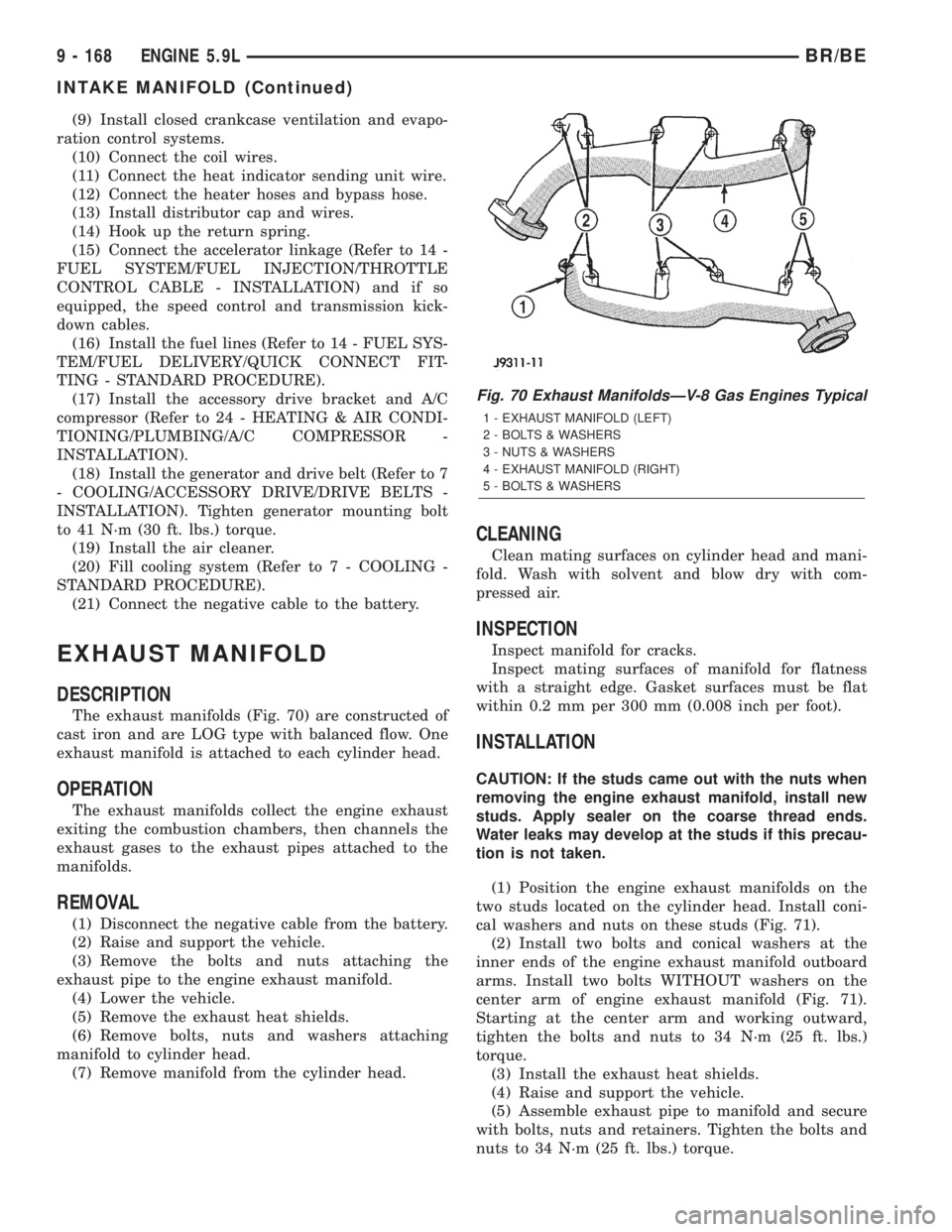
The exhaust manifolds (Fig. 70) are constructed of
cast iron and are LOG type with balanced flow. One
exhaust manifold is attached to each cylinder head.
OPERATION
The exhaust manifolds collect the engine exhaust
exiting the combustion chambers, then channels the
exhaust gases to the exhaust pipes attached to the
manifolds.
REMOVAL
(1) Disconnect the negative cable from the battery.
(2) Raise and support the vehicle.
(3) Remove the bolts and nuts attaching the
exhaust pipe to the engine exhaust manifold.
(4) Lower the vehicle.
(5) Remove the exhaust heat shields.
(6) Remove bolts, nuts and washers attaching
manifold to cylinder head.
(7) Remove manifold from the cylinder head.
CLEANING
Clean mating surfaces on cylinder head and mani-
fold. Wash with solvent and blow dry with com-
pressed air.
INSPECTION
Inspect manifold for cracks.
Inspect mating surfaces of manifold for flatness
with a straight edge. Gasket surfaces must be flat
within 0.2 mm per 300 mm (0.008 inch per foot).
INSTALLATION
CAUTION: If the studs came out with the nuts when
removing the engine exhaust manifold, install new
studs. Apply sealer on the coarse thread ends.
Water leaks may develop at the studs if this precau-
tion is not taken.
(1) Position the engine exhaust manifolds on the
two studs located on the cylinder head. Install coni-
cal washers and nuts on these studs (Fig. 71).
(2) Install two bolts and conical washers at the
inner ends of the engine exhaust manifold outboard
arms. Install two bolts WITHOUT washers on the
center arm of engine exhaust manifold (Fig. 71).
Starting at the center arm and working outward,
tighten the bolts and nuts to 34 N´m (25 ft. lbs.)
torque.
(3) Install the exhaust heat shields.
(4) Raise and support the vehicle.
(5) Assemble exhaust pipe to manifold and secure
with bolts, nuts and retainers. Tighten the bolts and
nuts to 34 N´m (25 ft. lbs.) torque.
Fig. 70 Exhaust ManifoldsÐV-8 Gas Engines Typical
1 - EXHAUST MANIFOLD (LEFT)
2 - BOLTS & WASHERS
3 - NUTS & WASHERS
4 - EXHAUST MANIFOLD (RIGHT)
5 - BOLTS & WASHERS
9 - 168 ENGINE 5.9LBR/BE
INTAKE MANIFOLD (Continued)
Page 1319 of 2889
LUBRICATION
DESCRIPTION..........................214
OPERATION............................214
DIAGNOSIS AND TESTING................215
ENGINE OIL LEAKS....................215
ENGINE OIL PRESSURE................215
OIL
STANDARD PROCEDURE.................217
ENGINE OIL..........................217
OIL FILTER
REMOVAL.............................218
INSTALLATION..........................218
OIL PAN
REMOVAL.............................218
CLEANING.............................218
INSPECTION...........................219
INSTALLATION..........................219
OIL PUMP
REMOVAL.............................219
CLEANING.............................220
INSPECTION...........................220
INSTALLATION..........................221INTAKE MANIFOLD
DESCRIPTION..........................222
DIAGNOSIS AND TESTING................222
INTAKE MANIFOLD LEAKAGE............222
REMOVAL.............................222
CLEANING.............................223
INSPECTION...........................223
INSTALLATION..........................223
EXHAUST MANIFOLD
DESCRIPTION..........................224
OPERATION............................224
REMOVAL.............................225
CLEANING.............................225
INSPECTION...........................225
INSTALLATION..........................225
TIMING BELT / CHAIN COVER(S)
REMOVAL.............................225
INSTALLATION..........................226
TIMING BELT/CHAIN AND SPROCKETS
REMOVAL.............................226
INSPECTION...........................227
INSTALLATION..........................227
ENGINE 8.0L
DESCRIPTION
The 8.0 Liter (488 CID) ten-cylinder engine is a
V-Type lightweight, single cam, overhead valveengine with hydraulic roller tappets. This engine is
designed for unleaded fuel.
Engine lubrication system consists of a gerotor type
oil pump mounted in the timing chain cover and driven
by the crankshaft. The V-10 uses a full flow oil filter.
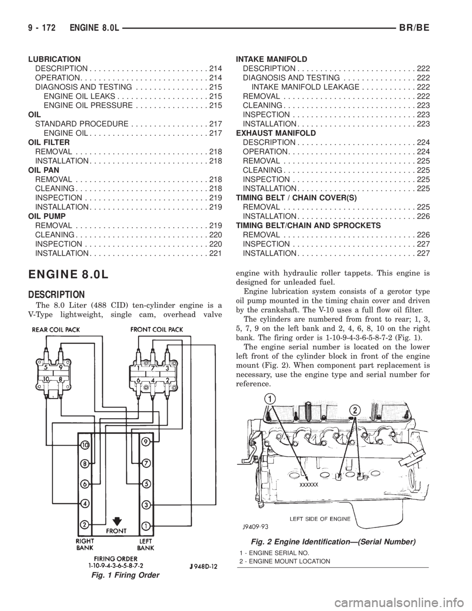
The cylinders are numbered from front to rear; 1, 3,
5, 7, 9 on the left bank and 2, 4, 6, 8, 10 on the right
bank. The firing order is 1-10-9-4-3-6-5-8-7-2 (Fig. 1).
The engine serial number is located on the lower
left front of the cylinder block in front of the engine
mount (Fig. 2). When component part replacement is
necessary, use the engine type and serial number for
reference.
Fig. 1 Firing Order
Fig. 2 Engine IdentificationÐ(Serial Number)
1 - ENGINE SERIAL NO.
2 - ENGINE MOUNT LOCATION
9 - 172 ENGINE 8.0LBR/BE
Page 1320 of 2889
DIAGNOSIS AND TESTINGÐENGINE
DIAGNOSIS - INTRODUCTION
Engine diagnosis is helpful in determining the
causes of malfunctions not detected and remedied by
routine maintenance.
These malfunctions may be classified as either
mechanical (e.g., a strange noise), or performance
(e.g., engine idles rough and stalls).
(Refer to 9 - ENGINE - DIAGNOSIS AND TEST-
ING - Preformance) or (Refer to 9 - ENGINE - DIAG-
NOSIS AND TESTING - Mechanical). Refer to 14 -
FUEL SYSTEM for fuel system diagnosis.Additional tests and diagnostic procedures may be
necessary for specific engine malfunctions that can-
not be isolated with the Service Diagnosis charts.
Information concerning additional tests and diagno-
sis is provided within the following:
²Cylinder Compression Pressure Test
²Cylinder Combustion Pressure Leakage Test
²Cylinder Head Gasket Failure Diagnosis
²Intake Manifold Leakage Diagnosis
²Lash Adjuster (Tappet) Noise Diagnosis
²Engine Oil Leak Inspection
DIAGNOSIS AND TESTINGÐPERFORMANCE
PERFORMANCE DIAGNOSIS CHARTÐGASOLINE ENGINES
CONDITION POSSIBLE CAUSES CORRECTION
ENGINE WILL NOT CRANK 1. Weak or dead battery 1. Charge/Replace Battery. (Refer to 8
- ELECTRICAL/BATTERY SYSTEM/
BATTERY - STANDARD
PROCEDURE). Check charging
system. (Refer to 8 - ELECTRICAL/
CHARGING - DIAGNOSIS AND
TESTING).
2. Corroded or loose battery
connections2. Clean/tighten suspect battery/
starter connections
3. Faulty starter or related circuit(s) 3. Check starting system. (Refer to 8 -
ELECTRICAL/STARTING -
DIAGNOSIS AND TESTING)
4. Seized accessory drive component 4. Remove accessory drive belt and
attempt to start engine. If engine
starts, repair/replace seized
component.
5. Engine internal mechanical failure
or hydro-static lock5. Refer to (Refer to 9 - ENGINE -
DIAGNOSIS AND TESTING)
ENGINE CRANKS BUT WILL NOT
START1. No spark 1. Check for spark. (Refer to 8 -
ELECTRICAL/IGNITION CONTROL -
DESCRIPTION)
2. No fuel 2. Perform fuel pressure test, and if
necessary, inspect fuel injector(s) and
driver circuits. (Refer to 14 - FUEL
SYSTEM/FUEL DELIVERY/FUEL
PUMP - DIAGNOSIS AND TESTING).
3. Low or no engine compression 3. Perform cylinder compression
pressure test. (Refer to 9 - ENGINE -
DIAGNOSIS AND TESTING).
BR/BEENGINE 8.0L 9 - 173
ENGINE 8.0L (Continued)
Page 1322 of 2889
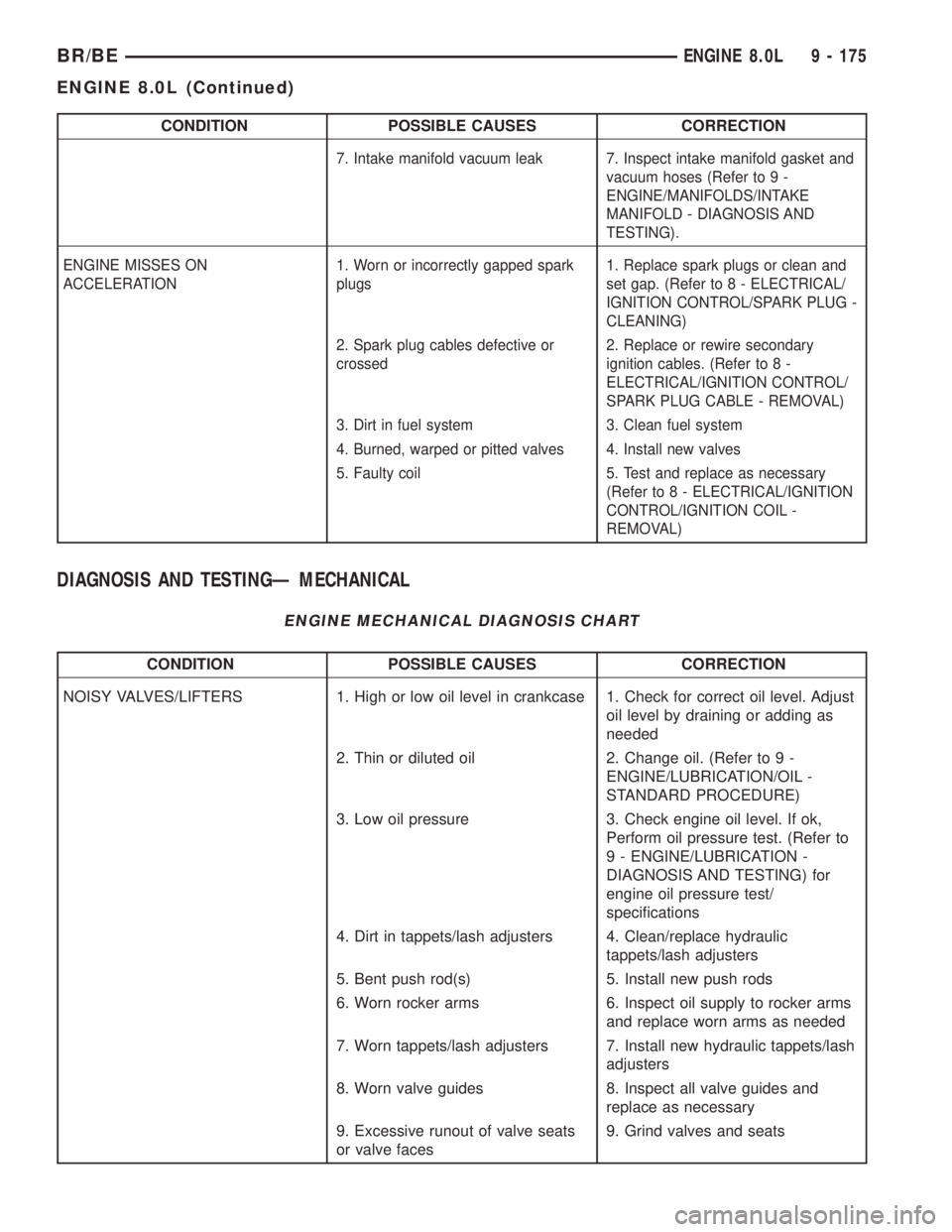
CONDITION POSSIBLE CAUSES CORRECTION
7. Intake manifold vacuum leak 7. Inspect intake manifold gasket and
vacuum hoses (Refer to 9 -
ENGINE/MANIFOLDS/INTAKE
MANIFOLD - DIAGNOSIS AND
TESTING).
ENGINE MISSES ON
ACCELERATION1. Worn or incorrectly gapped spark
plugs1. Replace spark plugs or clean and
set gap. (Refer to 8 - ELECTRICAL/
IGNITION CONTROL/SPARK PLUG -
CLEANING)
2. Spark plug cables defective or
crossed2. Replace or rewire secondary
ignition cables. (Refer to 8 -
ELECTRICAL/IGNITION CONTROL/
SPARK PLUG CABLE - REMOVAL)
3. Dirt in fuel system 3. Clean fuel system
4. Burned, warped or pitted valves 4. Install new valves
5. Faulty coil 5. Test and replace as necessary
(Refer to 8 - ELECTRICAL/IGNITION
CONTROL/IGNITION COIL -
REMOVAL)
DIAGNOSIS AND TESTINGÐ MECHANICAL
ENGINE MECHANICAL DIAGNOSIS CHART
CONDITION POSSIBLE CAUSES CORRECTION
NOISY VALVES/LIFTERS 1. High or low oil level in crankcase 1. Check for correct oil level. Adjust
oil level by draining or adding as
needed
2. Thin or diluted oil 2. Change oil. (Refer to 9 -
ENGINE/LUBRICATION/OIL -
STANDARD PROCEDURE)
3. Low oil pressure 3. Check engine oil level. If ok,
Perform oil pressure test. (Refer to
9 - ENGINE/LUBRICATION -
DIAGNOSIS AND TESTING) for
engine oil pressure test/
specifications
4. Dirt in tappets/lash adjusters 4. Clean/replace hydraulic
tappets/lash adjusters
5. Bent push rod(s) 5. Install new push rods
6. Worn rocker arms 6. Inspect oil supply to rocker arms
and replace worn arms as needed
7. Worn tappets/lash adjusters 7. Install new hydraulic tappets/lash
adjusters
8. Worn valve guides 8. Inspect all valve guides and
replace as necessary
9. Excessive runout of valve seats
or valve faces9. Grind valves and seats
BR/BEENGINE 8.0L 9 - 175
ENGINE 8.0L (Continued)
Page 1328 of 2889
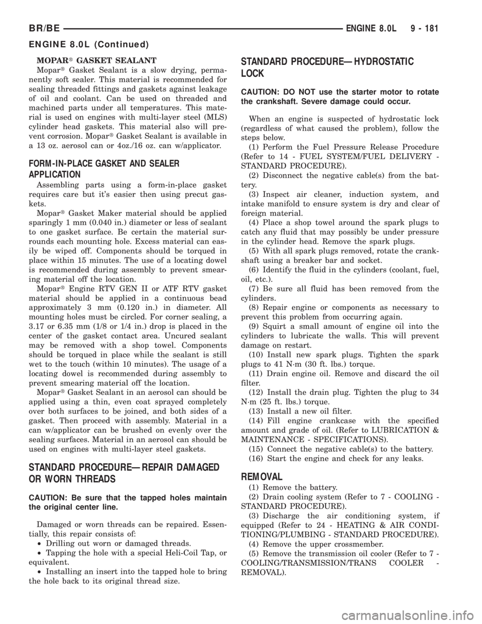
MOPARtGASKET SEALANT
MopartGasket Sealant is a slow drying, perma-
nently soft sealer. This material is recommended for
sealing threaded fittings and gaskets against leakage
of oil and coolant. Can be used on threaded and
machined parts under all temperatures. This mate-
rial is used on engines with multi-layer steel (MLS)
cylinder head gaskets. This material also will pre-
vent corrosion. MopartGasket Sealant is available in
a 13 oz. aerosol can or 4oz./16 oz. can w/applicator.
FORM-IN-PLACE GASKET AND SEALER
APPLICATION
Assembling parts using a form-in-place gasket
requires care but it's easier then using precut gas-
kets.
MopartGasket Maker material should be applied
sparingly 1 mm (0.040 in.) diameter or less of sealant
to one gasket surface. Be certain the material sur-
rounds each mounting hole. Excess material can eas-
ily be wiped off. Components should be torqued in
place within 15 minutes. The use of a locating dowel
is recommended during assembly to prevent smear-
ing material off the location.
MopartEngine RTV GEN II or ATF RTV gasket
material should be applied in a continuous bead
approximately 3 mm (0.120 in.) in diameter. All
mounting holes must be circled. For corner sealing, a
3.17 or 6.35 mm (1/8 or 1/4 in.) drop is placed in the
center of the gasket contact area. Uncured sealant
may be removed with a shop towel. Components
should be torqued in place while the sealant is still
wet to the touch (within 10 minutes). The usage of a
locating dowel is recommended during assembly to
prevent smearing material off the location.
MopartGasket Sealant in an aerosol can should be
applied using a thin, even coat sprayed completely
over both surfaces to be joined, and both sides of a
gasket. Then proceed with assembly. Material in a
can w/applicator can be brushed on evenly over the
sealing surfaces. Material in an aerosol can should be
used on engines with multi-layer steel gaskets.
STANDARD PROCEDUREÐREPAIR DAMAGED
OR WORN THREADS
CAUTION: Be sure that the tapped holes maintain
the original center line.
Damaged or worn threads can be repaired. Essen-
tially, this repair consists of:
²Drilling out worn or damaged threads.
²Tapping the hole with a special Heli-Coil Tap, or
equivalent.
²Installing an insert into the tapped hole to bring
the hole back to its original thread size.
STANDARD PROCEDUREÐHYDROSTATIC
LOCK
CAUTION: DO NOT use the starter motor to rotate
the crankshaft. Severe damage could occur.
When an engine is suspected of hydrostatic lock
(regardless of what caused the problem), follow the
steps below.
(1) Perform the Fuel Pressure Release Procedure
(Refer to 14 - FUEL SYSTEM/FUEL DELIVERY -
STANDARD PROCEDURE).
(2) Disconnect the negative cable(s) from the bat-
tery.
(3) Inspect air cleaner, induction system, and
intake manifold to ensure system is dry and clear of
foreign material.
(4) Place a shop towel around the spark plugs to
catch any fluid that may possibly be under pressure
in the cylinder head. Remove the spark plugs.
(5) With all spark plugs removed, rotate the crank-
shaft using a breaker bar and socket.
(6) Identify the fluid in the cylinders (coolant, fuel,
oil, etc.).
(7) Be sure all fluid has been removed from the
cylinders.
(8) Repair engine or components as necessary to
prevent this problem from occurring again.
(9) Squirt a small amount of engine oil into the
cylinders to lubricate the walls. This will prevent
damage on restart.
(10) Install new spark plugs. Tighten the spark
plugs to 41 N´m (30 ft. lbs.) torque.
(11) Drain engine oil. Remove and discard the oil
filter.
(12) Install the drain plug. Tighten the plug to 34
N´m (25 ft. lbs.) torque.
(13) Install a new oil filter.
(14) Fill engine crankcase with the specified
amount and grade of oil. (Refer to LUBRICATION &
MAINTENANCE - SPECIFICATIONS).
(15) Connect the negative cable(s) to the battery.
(16) Start the engine and check for any leaks.
REMOVAL
(1) Remove the battery.
(2) Drain cooling system (Refer to 7 - COOLING -
STANDARD PROCEDURE).
(3) Discharge the air conditioning system, if
equipped (Refer to 24 - HEATING & AIR CONDI-
TIONING/PLUMBING - STANDARD PROCEDURE).
(4) Remove the upper crossmember.
(5) Remove the transmission oil cooler (Refer to 7 -
COOLING/TRANSMISSION/TRANS COOLER -
REMOVAL).
BR/BEENGINE 8.0L 9 - 181
ENGINE 8.0L (Continued)
Page 1329 of 2889
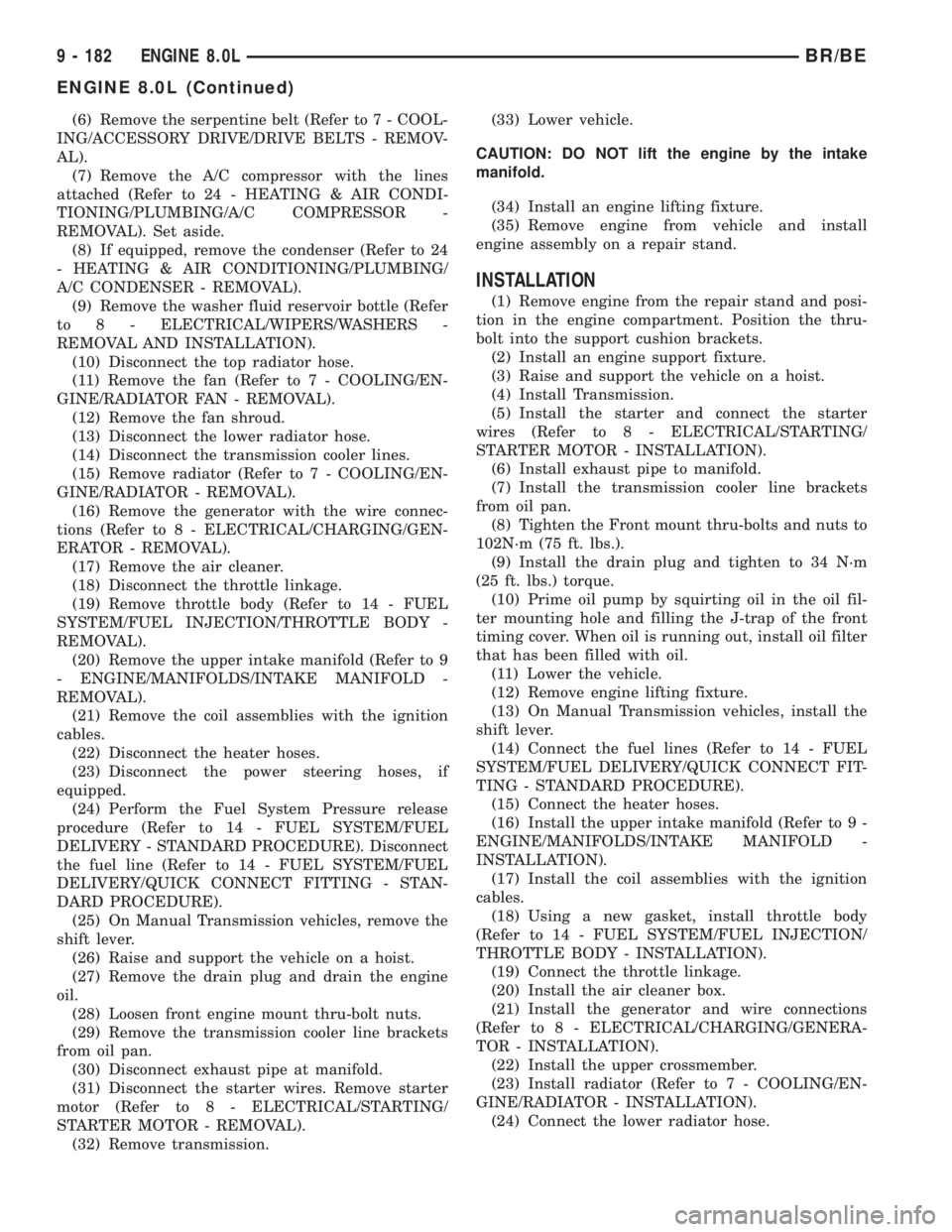
(6) Remove the serpentine belt (Refer to 7 - COOL-
ING/ACCESSORY DRIVE/DRIVE BELTS - REMOV-
AL).
(7) Remove the A/C compressor with the lines
attached (Refer to 24 - HEATING & AIR CONDI-
TIONING/PLUMBING/A/C COMPRESSOR -
REMOVAL). Set aside.
(8) If equipped, remove the condenser (Refer to 24
- HEATING & AIR CONDITIONING/PLUMBING/
A/C CONDENSER - REMOVAL).
(9) Remove the washer fluid reservoir bottle (Refer
to 8 - ELECTRICAL/WIPERS/WASHERS -
REMOVAL AND INSTALLATION).
(10) Disconnect the top radiator hose.
(11) Remove the fan (Refer to 7 - COOLING/EN-
GINE/RADIATOR FAN - REMOVAL).
(12) Remove the fan shroud.
(13) Disconnect the lower radiator hose.
(14) Disconnect the transmission cooler lines.
(15) Remove radiator (Refer to 7 - COOLING/EN-
GINE/RADIATOR - REMOVAL).
(16) Remove the generator with the wire connec-
tions (Refer to 8 - ELECTRICAL/CHARGING/GEN-
ERATOR - REMOVAL).
(17) Remove the air cleaner.
(18) Disconnect the throttle linkage.
(19) Remove throttle body (Refer to 14 - FUEL
SYSTEM/FUEL INJECTION/THROTTLE BODY -
REMOVAL).
(20) Remove the upper intake manifold (Refer to 9
- ENGINE/MANIFOLDS/INTAKE MANIFOLD -
REMOVAL).
(21) Remove the coil assemblies with the ignition
cables.
(22) Disconnect the heater hoses.
(23) Disconnect the power steering hoses, if
equipped.
(24) Perform the Fuel System Pressure release
procedure (Refer to 14 - FUEL SYSTEM/FUEL
DELIVERY - STANDARD PROCEDURE). Disconnect
the fuel line (Refer to 14 - FUEL SYSTEM/FUEL
DELIVERY/QUICK CONNECT FITTING - STAN-
DARD PROCEDURE).
(25) On Manual Transmission vehicles, remove the
shift lever.
(26) Raise and support the vehicle on a hoist.
(27) Remove the drain plug and drain the engine
oil.
(28) Loosen front engine mount thru-bolt nuts.
(29) Remove the transmission cooler line brackets
from oil pan.
(30) Disconnect exhaust pipe at manifold.
(31) Disconnect the starter wires. Remove starter
motor (Refer to 8 - ELECTRICAL/STARTING/
STARTER MOTOR - REMOVAL).
(32) Remove transmission.(33) Lower vehicle.
CAUTION: DO NOT lift the engine by the intake
manifold.
(34) Install an engine lifting fixture.
(35) Remove engine from vehicle and install
engine assembly on a repair stand.
INSTALLATION
(1) Remove engine from the repair stand and posi-
tion in the engine compartment. Position the thru-
bolt into the support cushion brackets.
(2) Install an engine support fixture.
(3) Raise and support the vehicle on a hoist.
(4) Install Transmission.
(5) Install the starter and connect the starter
wires (Refer to 8 - ELECTRICAL/STARTING/
STARTER MOTOR - INSTALLATION).
(6) Install exhaust pipe to manifold.
(7) Install the transmission cooler line brackets
from oil pan.
(8) Tighten the Front mount thru-bolts and nuts to
102N´m (75 ft. lbs.).
(9) Install the drain plug and tighten to 34 N´m
(25 ft. lbs.) torque.
(10) Prime oil pump by squirting oil in the oil fil-
ter mounting hole and filling the J-trap of the front
timing cover. When oil is running out, install oil filter
that has been filled with oil.
(11) Lower the vehicle.
(12) Remove engine lifting fixture.
(13) On Manual Transmission vehicles, install the
shift lever.
(14) Connect the fuel lines (Refer to 14 - FUEL
SYSTEM/FUEL DELIVERY/QUICK CONNECT FIT-
TING - STANDARD PROCEDURE).
(15) Connect the heater hoses.
(16) Install the upper intake manifold (Refer to 9 -
ENGINE/MANIFOLDS/INTAKE MANIFOLD -
INSTALLATION).
(17) Install the coil assemblies with the ignition
cables.
(18) Using a new gasket, install throttle body
(Refer to 14 - FUEL SYSTEM/FUEL INJECTION/
THROTTLE BODY - INSTALLATION).
(19) Connect the throttle linkage.
(20) Install the air cleaner box.
(21) Install the generator and wire connections
(Refer to 8 - ELECTRICAL/CHARGING/GENERA-
TOR - INSTALLATION).
(22) Install the upper crossmember.
(23) Install radiator (Refer to 7 - COOLING/EN-
GINE/RADIATOR - INSTALLATION).
(24) Connect the lower radiator hose.
9 - 182 ENGINE 8.0LBR/BE
ENGINE 8.0L (Continued)
Page 1334 of 2889
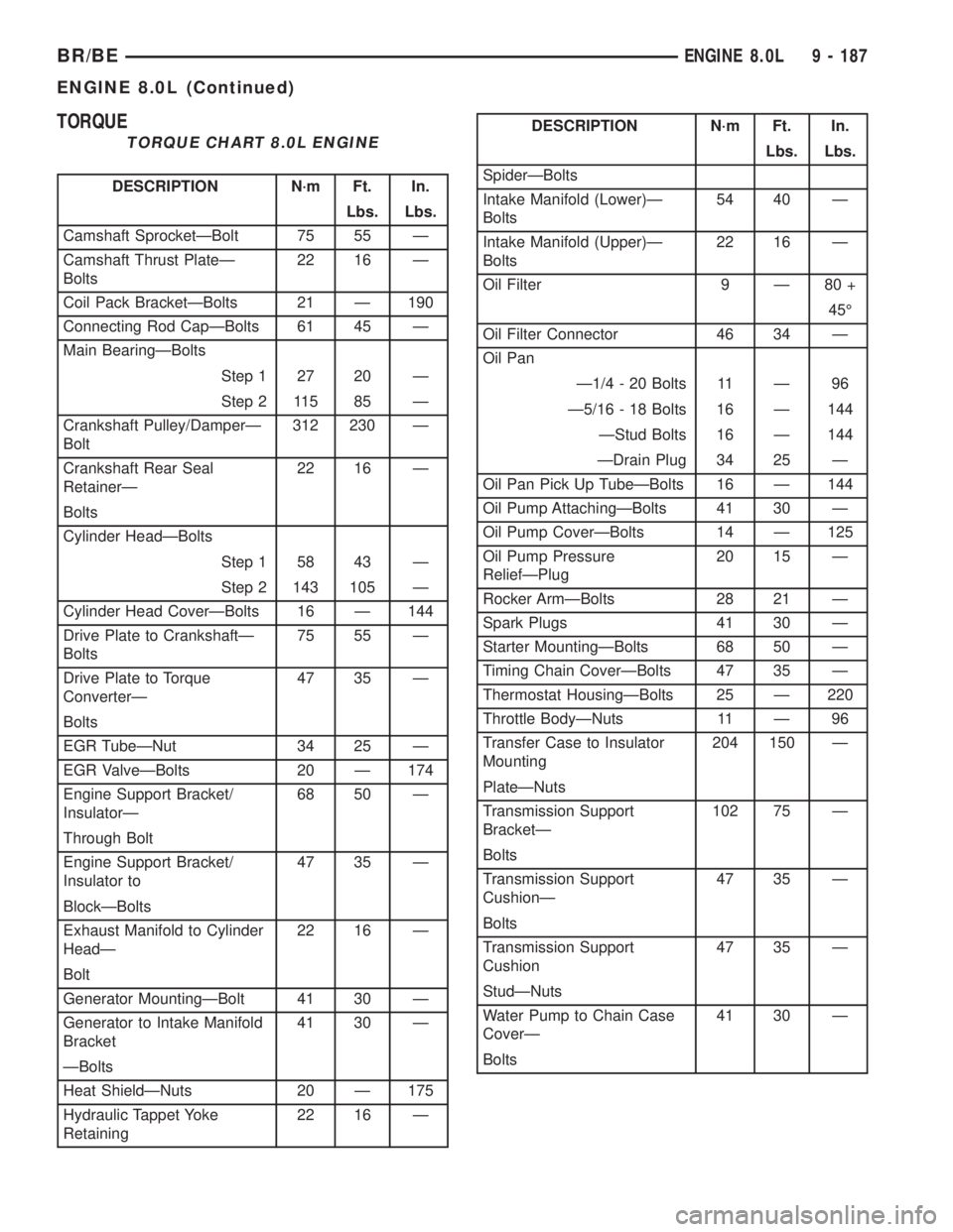
TORQUE
TORQUE CHART 8.0L ENGINE
DESCRIPTION N´m Ft. In.
Lbs. Lbs.
Camshaft SprocketÐBolt 75 55 Ð
Camshaft Thrust PlateÐ
Bolts22 16 Ð
Coil Pack BracketÐBolts 21 Ð 190
Connecting Rod CapÐBolts 61 45 Ð
Main BearingÐBolts
Step 1 27 20 Ð
Step 2 115 85 Ð
Crankshaft Pulley/DamperÐ
Bolt312 230 Ð
Crankshaft Rear Seal
RetainerÐ22 16 Ð
Bolts
Cylinder HeadÐBolts
Step 1 58 43 Ð
Step 2 143 105 Ð
Cylinder Head CoverÐBolts 16 Ð 144
Drive Plate to CrankshaftÐ
Bolts75 55 Ð
Drive Plate to Torque
ConverterÐ47 35 Ð
Bolts
EGR TubeÐNut 34 25 Ð
EGR ValveÐBolts 20 Ð 174
Engine Support Bracket/
InsulatorÐ68 50 Ð
Through Bolt
Engine Support Bracket/
Insulator to47 35 Ð
BlockÐBolts
Exhaust Manifold to Cylinder
HeadÐ22 16 Ð
Bolt
Generator MountingÐBolt 41 30 Ð
Generator to Intake Manifold
Bracket41 30 Ð
ÐBolts
Heat ShieldÐNuts 20 Ð 175
Hydraulic Tappet Yoke
Retaining22 16 Ð
DESCRIPTION N´m Ft. In.
Lbs. Lbs.
SpiderÐBolts
Intake Manifold (Lower)Ð
Bolts54 40 Ð
Intake Manifold (Upper)Ð
Bolts22 16 Ð
Oil Filter 9 Ð 80 +
45É
Oil Filter Connector 46 34 Ð
Oil Pan
Ð1/4 - 20 Bolts 11 Ð 96
Ð5/16 - 18 Bolts 16 Ð 144
ÐStud Bolts 16 Ð 144
ÐDrain Plug 34 25 Ð
Oil Pan Pick Up TubeÐBolts 16 Ð 144
Oil Pump AttachingÐBolts 41 30 Ð
Oil Pump CoverÐBolts 14 Ð 125
Oil Pump Pressure
ReliefÐPlug20 15 Ð
Rocker ArmÐBolts 28 21 Ð
Spark Plugs 41 30 Ð
Starter MountingÐBolts 68 50 Ð
Timing Chain CoverÐBolts 47 35 Ð
Thermostat HousingÐBolts 25 Ð 220
Throttle BodyÐNuts 11 Ð 96
Transfer Case to Insulator
Mounting204 150 Ð
PlateÐNuts
Transmission Support
BracketÐ102 75 Ð
Bolts
Transmission Support
CushionÐ47 35 Ð
Bolts
Transmission Support
Cushion47 35 Ð
StudÐNuts
Water Pump to Chain Case
CoverÐ41 30 Ð
Bolts
BR/BEENGINE 8.0L 9 - 187
ENGINE 8.0L (Continued)