2001 CHRYSLER VOYAGER sensor
[x] Cancel search: sensorPage 2873 of 4284
FUEL SYSTEM
TABLE OF CONTENTS
page page
FUEL DELIVERY..........................1FUEL INJECTION........................16
FUEL DELIVERY
TABLE OF CONTENTS
page page
FUEL DELIVERY
DESCRIPTION............................1
OPERATION.............................2
DIAGNOSIS AND TESTING..................2
FUEL DELIVERY SYSTEM.................2
STANDARD PROCEDURE...................2
FUEL PRESS RELEASE...................2
STANDARD PROCEDURE.................2
SPECIFICATIONS.........................2
SPECIAL TOOLS..........................3
FUEL FILTER
REMOVAL...............................4
INSTALLATION............................4
FUEL LEVEL SENDING UNIT / SENSOR
DESCRIPTION............................4
OPERATION.............................4
REMOVAL...............................4
INSTALLATION............................5
FUEL LINES
DESCRIPTION............................6
STANDARD PROCEDURE...................6
HOSES & CLAMP........................6
FUEL PRESSURE REGULATOR
OPERATION.............................6
REMOVAL...............................7
INSTALLATION............................7
FUEL PUMP
DESCRIPTION............................7OPERATION.............................7
FUEL PUMP MODULE
DESCRIPTION............................7
OPERATION.............................7
REMOVAL...............................8
INSTALLATION............................8
FUEL RAIL
REMOVAL...............................9
INSTALLATION............................9
FUEL TANK
DESCRIPTION...........................10
OPERATION.............................10
REMOVAL..............................10
INSTALLATION...........................11
FUEL TANK FILLER TUBE
REMOVAL..............................12
INSTALLATION...........................12
INLET FILTER
REMOVAL..............................13
INSTALLATION...........................13
QUICK CONNECT FITTING
STANDARD PROCEDURE..................13
QUICK CONNECT FITTING...............13
ROLLOVER VALVE
DESCRIPTION...........................15
OPERATION.............................15
FUEL DELIVERY
DESCRIPTION
The front wheel drive car uses a plastic fuel tank
located rear center of the vehicle.
The Fuel Delivery System consists of: the following
items:²Electric fuel pump module
²Fuel filter
²Tubes/lines/hoses
²Fuel injectors
The in-tank fuel pump module contains the fuel
pump. The pump is serviced as part of the fuel pump
module. Refer to Fuel Pump Module.
RSFUEL SYSTEM14-1
Page 2874 of 4284
The fuel filter is replaceable, it is mounted on the
outside and on top of the fuel tank. Refer to the
Maintenance Schedules in the Introduction section of
this manual for recommended fuel filter replacement
intervals.
FFV REPLACEMENT PARTS
Many components in a Flexible Fuel Vehicle (FFV)
are designed to be compatible with ethanol. Always
be sure that the vehicle is serviced with correct etha-
nol compatible parts.
CAUTION: Replacing fuel system components with
non-ethanol compatible components can damage
your vehicle and may void the warranty.
OPERATION
The fuel system is provided fuel pressure by an in-
tank pump module. The PCM controls the operation
of the fuel system by providing battery voltage to the
fuel pump through the fuel pump relay. The PCM
requires only three inputs and a good ground to oper-
ate the fuel pump relay. The three inputs are:
²Ignition voltage
²Crankshaft Position (CKP) sensor
²Camshaft Position (CMP) sensor
DIAGNOSIS AND TESTING - FUEL DELIVERY
SYSTEM
(Refer to Appropriate Diagnositic Information)
STANDARD PROCEDURE - FUEL SYSTEM
PRESSURE RELEASE PROCEDURE
(1) Remove Fuel Pump relay from Power Distribu-
tion Center (PDC). For location of relay, refer to label
on underside of PDC cover.(2) Start and run engine until it stalls.
(3) Attempt restarting engine until it will no
longer run.
(4) Turn ignition key to OFF position.
(5) Place a rag or towel below fuel line quick-con-
nect fitting at fuel rail.
(6) Return fuel pump relay to PDC.
(7) One or more Diagnostic Trouble Codes (DTC's)
may have been stored in PCM memory due to fuel
pump relay removal. The DRB IIItscan tool must be
used to erase a DTC.
STANDARD PROCEDURE - DRAINING FUEL
TANK
(1) Release fuel system pressure, refer to the Fuel
System Release Procedure in this section.
(2) Insert a 1/4 inch siphon (max. O. D. 5/16) hose
from a portable fuel siphoning tank through the fuel
filler neck opening into the fuel tank. Hose most
have a 30 degree angle cut on the end to bypass the
check valve in the end of the filler neck. Refer to the
siphoning tank's Manufacturing Instructions.
(3) Drain fuel from fuel tank into siphoning tank.
SPECIFICATIONS
FUEL SYSTEM PRESSURE
400 kpa634 kpa (58 psi65 psi)
TORQUE
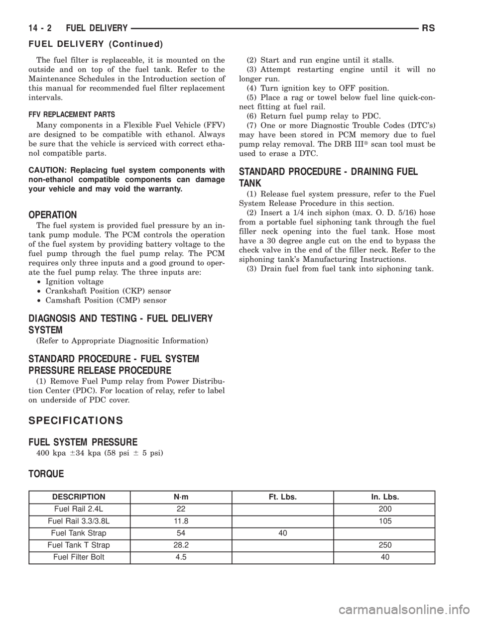
DESCRIPTION N´m Ft. Lbs. In. Lbs.
Fuel Rail 2.4L 22 200
Fuel Rail 3.3/3.8L 11.8 105
Fuel Tank Strap 54 40
Fuel Tank T Strap 28.2 250
Fuel Filter Bolt 4.5 40
14 - 2 FUEL DELIVERYRS
FUEL DELIVERY (Continued)
Page 2875 of 4284
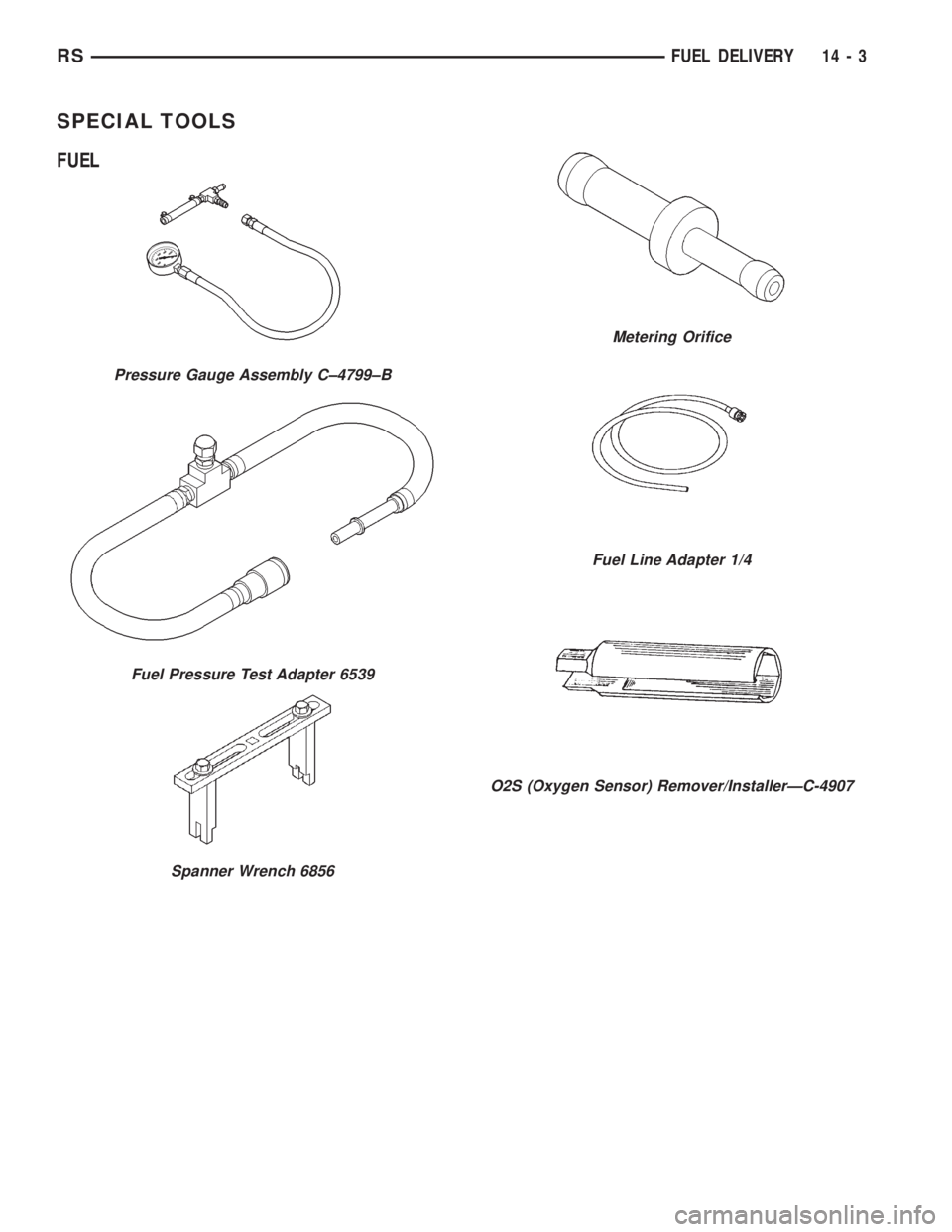
SPECIAL TOOLS
FUEL
Pressure Gauge Assembly C±4799±B
Fuel Pressure Test Adapter 6539
Spanner Wrench 6856
Metering Orifice
Fuel Line Adapter 1/4
O2S (Oxygen Sensor) Remover/InstallerÐC-4907
RSFUEL DELIVERY14-3
Page 2876 of 4284
FUEL FILTER
REMOVAL
(1) Release fuel pressure, refer to the Fuel release
procedure in this section.
(2) Disconnect the negative battery cable.
(3) Raise vehicle and support.
(4) Support the fuel tank with a transmission jack.
(5) Remove fuel line from the front of the tank.
(6) Remove ground strap
(7) Remove the inboard side of the fuel tank straps
and front T strap fastner.
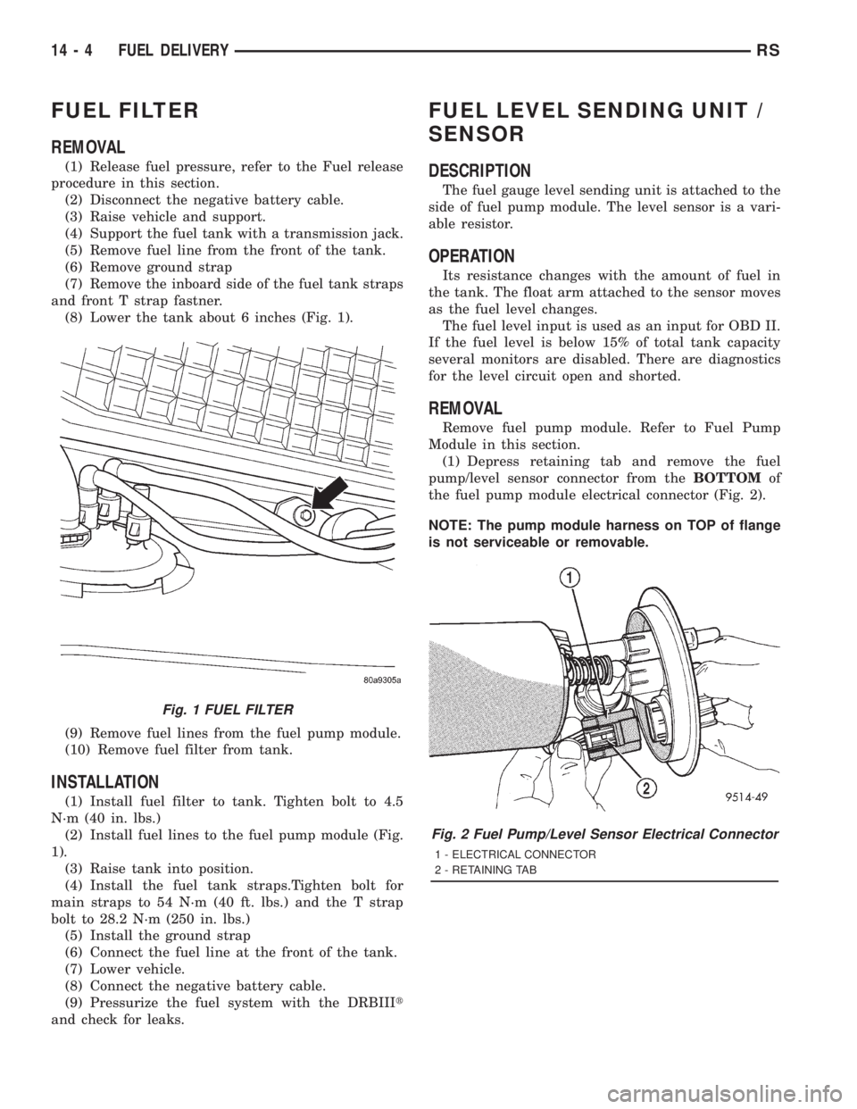
(8) Lower the tank about 6 inches (Fig. 1).
(9) Remove fuel lines from the fuel pump module.
(10) Remove fuel filter from tank.
INSTALLATION
(1) Install fuel filter to tank. Tighten bolt to 4.5
N´m (40 in. lbs.)
(2) Install fuel lines to the fuel pump module (Fig.
1).
(3) Raise tank into position.
(4) Install the fuel tank straps.Tighten bolt for
main straps to 54 N´m (40 ft. lbs.) and the T strap
bolt to 28.2 N´m (250 in. lbs.)
(5) Install the ground strap
(6) Connect the fuel line at the front of the tank.
(7) Lower vehicle.
(8) Connect the negative battery cable.
(9) Pressurize the fuel system with the DRBIIIt
and check for leaks.
FUEL LEVEL SENDING UNIT /
SENSOR
DESCRIPTION
The fuel gauge level sending unit is attached to the
side of fuel pump module. The level sensor is a vari-
able resistor.
OPERATION
Its resistance changes with the amount of fuel in
the tank. The float arm attached to the sensor moves
as the fuel level changes.
The fuel level input is used as an input for OBD II.
If the fuel level is below 15% of total tank capacity
several monitors are disabled. There are diagnostics
for the level circuit open and shorted.
REMOVAL
Remove fuel pump module. Refer to Fuel Pump
Module in this section.
(1) Depress retaining tab and remove the fuel
pump/level sensor connector from theBOTTOMof
the fuel pump module electrical connector (Fig. 2).
NOTE: The pump module harness on TOP of flange
is not serviceable or removable.
Fig. 1 FUEL FILTER
Fig. 2 Fuel Pump/Level Sensor Electrical Connector
1 - ELECTRICAL CONNECTOR
2 - RETAINING TAB
14 - 4 FUEL DELIVERYRS
Page 2877 of 4284
(2) Pull off the locking wedge.
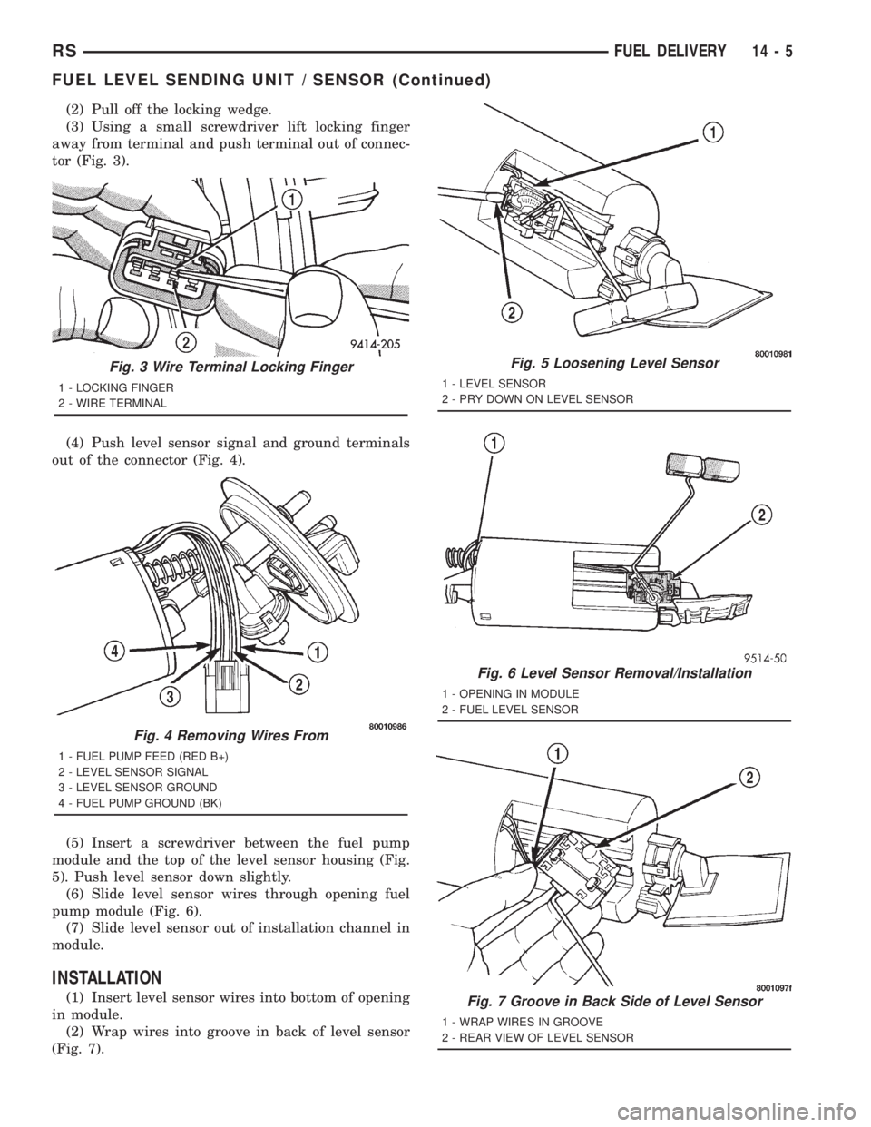
(3) Using a small screwdriver lift locking finger
away from terminal and push terminal out of connec-
tor (Fig. 3).
(4) Push level sensor signal and ground terminals
out of the connector (Fig. 4).
(5) Insert a screwdriver between the fuel pump
module and the top of the level sensor housing (Fig.
5). Push level sensor down slightly.
(6) Slide level sensor wires through opening fuel
pump module (Fig. 6).
(7) Slide level sensor out of installation channel in
module.
INSTALLATION
(1) Insert level sensor wires into bottom of opening
in module.
(2) Wrap wires into groove in back of level sensor
(Fig. 7).
Fig. 3 Wire Terminal Locking Finger
1 - LOCKING FINGER
2 - WIRE TERMINAL
Fig. 4 Removing Wires From
1 - FUEL PUMP FEED (RED B+)
2 - LEVEL SENSOR SIGNAL
3 - LEVEL SENSOR GROUND
4 - FUEL PUMP GROUND (BK)
Fig. 5 Loosening Level Sensor
1 - LEVEL SENSOR
2 - PRY DOWN ON LEVEL SENSOR
Fig. 6 Level Sensor Removal/Installation
1 - OPENING IN MODULE
2 - FUEL LEVEL SENSOR
Fig. 7 Groove in Back Side of Level Sensor
1 - WRAP WIRES IN GROOVE
2 - REAR VIEW OF LEVEL SENSOR
RSFUEL DELIVERY14-5
FUEL LEVEL SENDING UNIT / SENSOR (Continued)
Page 2878 of 4284
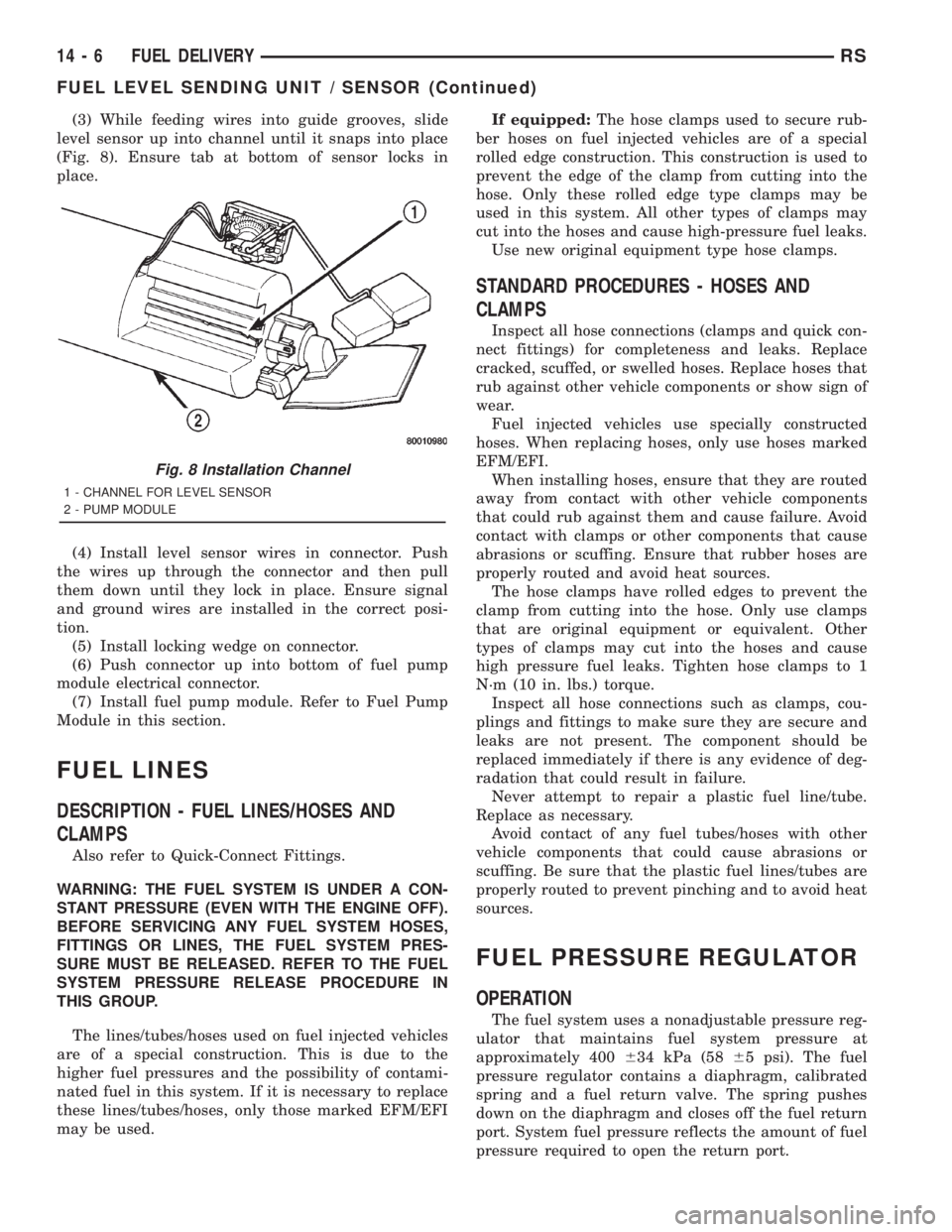
(3) While feeding wires into guide grooves, slide
level sensor up into channel until it snaps into place
(Fig. 8). Ensure tab at bottom of sensor locks in
place.
(4) Install level sensor wires in connector. Push
the wires up through the connector and then pull
them down until they lock in place. Ensure signal
and ground wires are installed in the correct posi-
tion.
(5) Install locking wedge on connector.
(6) Push connector up into bottom of fuel pump
module electrical connector.
(7) Install fuel pump module. Refer to Fuel Pump
Module in this section.
FUEL LINES
DESCRIPTION - FUEL LINES/HOSES AND
CLAMPS
Also refer to Quick-Connect Fittings.
WARNING: THE FUEL SYSTEM IS UNDER A CON-
STANT PRESSURE (EVEN WITH THE ENGINE OFF).
BEFORE SERVICING ANY FUEL SYSTEM HOSES,
FITTINGS OR LINES, THE FUEL SYSTEM PRES-
SURE MUST BE RELEASED. REFER TO THE FUEL
SYSTEM PRESSURE RELEASE PROCEDURE IN
THIS GROUP.
The lines/tubes/hoses used on fuel injected vehicles
are of a special construction. This is due to the
higher fuel pressures and the possibility of contami-
nated fuel in this system. If it is necessary to replace
these lines/tubes/hoses, only those marked EFM/EFI
may be used.If equipped:The hose clamps used to secure rub-
ber hoses on fuel injected vehicles are of a special
rolled edge construction. This construction is used to
prevent the edge of the clamp from cutting into the
hose. Only these rolled edge type clamps may be
used in this system. All other types of clamps may
cut into the hoses and cause high-pressure fuel leaks.
Use new original equipment type hose clamps.
STANDARD PROCEDURES - HOSES AND
CLAMPS
Inspect all hose connections (clamps and quick con-
nect fittings) for completeness and leaks. Replace
cracked, scuffed, or swelled hoses. Replace hoses that
rub against other vehicle components or show sign of
wear.
Fuel injected vehicles use specially constructed
hoses. When replacing hoses, only use hoses marked
EFM/EFI.
When installing hoses, ensure that they are routed
away from contact with other vehicle components
that could rub against them and cause failure. Avoid
contact with clamps or other components that cause
abrasions or scuffing. Ensure that rubber hoses are
properly routed and avoid heat sources.
The hose clamps have rolled edges to prevent the
clamp from cutting into the hose. Only use clamps
that are original equipment or equivalent. Other
types of clamps may cut into the hoses and cause
high pressure fuel leaks. Tighten hose clamps to 1
N´m (10 in. lbs.) torque.
Inspect all hose connections such as clamps, cou-
plings and fittings to make sure they are secure and
leaks are not present. The component should be
replaced immediately if there is any evidence of deg-
radation that could result in failure.
Never attempt to repair a plastic fuel line/tube.
Replace as necessary.
Avoid contact of any fuel tubes/hoses with other
vehicle components that could cause abrasions or
scuffing. Be sure that the plastic fuel lines/tubes are
properly routed to prevent pinching and to avoid heat
sources.
FUEL PRESSURE REGULATOR
OPERATION
The fuel system uses a nonadjustable pressure reg-
ulator that maintains fuel system pressure at
approximately 400634 kPa (5865 psi). The fuel
pressure regulator contains a diaphragm, calibrated
spring and a fuel return valve. The spring pushes
down on the diaphragm and closes off the fuel return
port. System fuel pressure reflects the amount of fuel
pressure required to open the return port.
Fig. 8 Installation Channel
1 - CHANNEL FOR LEVEL SENSOR
2 - PUMP MODULE
14 - 6 FUEL DELIVERYRS
FUEL LEVEL SENDING UNIT / SENSOR (Continued)
Page 2879 of 4284
The pressure regulator is a mechanical device that
is NOT controlled by the PCM or engine vacuum.
REMOVAL
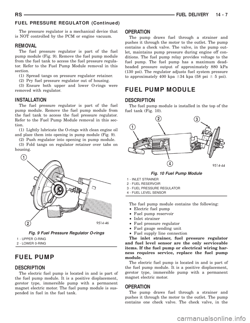
The fuel pressure regulator is part of the fuel
pump module (Fig. 9). Remove the fuel pump module
from the fuel tank to access the fuel pressure regula-
tor. Refer to the Fuel Pump Module removal in this
section.
(1) Spread tangs on pressure regulator retainer.
(2) Pry fuel pressure regulator out of housing.
(3) Ensure both upper and lower O-rings were
removed with regulator.
INSTALLATION
The fuel pressure regulator is part of the fuel
pump module. Remove the fuel pump module from
the fuel tank to access the fuel pressure regulator.
Refer to the Fuel Pump Module removal in this sec-
tion.
(1)
Lightly lubricate the O-rings with clean engine oil
and place them into opening in pump module (Fig. 9).
(2) Push regulator into opening in pump module.
(3) Fold tangs on regulator retainer over tabs on
housing.
FUEL PUMP
DESCRIPTION
The electric fuel pump is located in and is part of
the fuel pump module. It is a positive displacement,
gerotor type, immersible pump with a permanent
magnet electric motor. The fuel pump module is sus-
pended in fuel in the fuel tank.
OPERATION
The pump draws fuel through a strainer and
pushes it through the motor to the outlet. The pump
contains a check valve. The valve, in the pump out-
let, maintains pump pressure during engine off con-
ditions. The fuel pump relay provides voltage to the
fuel pump. The fuel pump has a maximum dead-
headed pressure output of approximately 880 kPa
(130 psi). The regulator adjusts fuel system pressure
to approximately 400 kpa634 kpa (58 psi65 psi).
FUEL PUMP MODULE
DESCRIPTION
The fuel pump module is installed in the top of the
fuel tank (Fig. 10).
The fuel pump module contains the following:
²Electric fuel pump
²Fuel pump reservoir
²Inlet strainer
²Fuel pressure regulator
²Fuel gauge sending unit
²Fuel supply line connection
The inlet strainer, fuel pressure regulator
and fuel level sensor are the only serviceable
items. If the fuel pump or electrical wiring har-
ness requires service, replace the fuel pump
module.
The electric fuel pump is located in and is part of
the fuel pump module. It is a positive displacement,
gerotor type, immersible pump with a permanent
magnet electric motor.
OPERATION
The pump draws fuel through a strainer and
pushes it through the motor to the outlet. The pump
contains one check valve. The check valve, in the
Fig. 9 Fuel Pressure Regulator O-rings
1 - UPPER O-RING
2 - LOWER 0-RING
Fig. 10 Fuel Pump Module
1 - INLET STRAINER
2 - FUEL RESERVOIR
3 - FUEL PRESSURE REGULATOR
4 - FUEL LEVEL SENSOR
RSFUEL DELIVERY14-7
FUEL PRESSURE REGULATOR (Continued)
Page 2888 of 4284
FUEL INJECTION
TABLE OF CONTENTS
page page
FUEL INJECTION
OPERATION.............................16
SPECIFICATIONS........................21
SPECIAL TOOLS.........................22
ACCELERATOR PEDAL
REMOVAL..............................23
INSTALLATION...........................23
CRANKSHAFT POSITION SENSOR
DESCRIPTION...........................23
OPERATION.............................23
REMOVAL..............................23
INSTALLATION...........................24
ENGINE SPEED SENSOR
DESCRIPTION...........................24
OPERATION.............................24
FUEL INJECTOR
DESCRIPTION...........................25
OPERATION.............................25
REMOVAL..............................25
INSTALLATION...........................26
FUEL PUMP RELAY
DESCRIPTION...........................27
OPERATION.............................27
IDLE AIR CONTROL MOTOR
DESCRIPTION...........................27
OPERATION.............................27
REMOVAL..............................28INSTALLATION...........................28
INLET AIR TEMPERATURE SENSOR
DESCRIPTION...........................28
OPERATION.............................28
MAP SENSOR
DESCRIPTION...........................29
OPERATION.............................29
REMOVAL..............................30
INSTALLATION...........................30
O2 SENSOR
DESCRIPTION...........................30
OPERATION.............................31
REMOVAL..............................32
INSTALLATION...........................33
THROTTLE BODY
DESCRIPTION...........................33
OPERATION.............................34
REMOVAL..............................34
INSTALLATION...........................34
THROTTLE CONTROL CABLE
REMOVAL..............................34
INSTALLATION...........................34
THROTTLE POSITION SENSOR
DESCRIPTION...........................34
OPERATION.............................35
REMOVAL..............................35
INSTALLATION...........................35
FUEL INJECTION
OPERATION - INJECTION SYSTEM
All engines used in this section have a sequential
Multi-Port Electronic Fuel Injection system. The MPI
system is computer regulated and provides precise
air/fuel ratios for all driving conditions. The Power-
train Control Module (PCM) operates the fuel injec-
tion system.
The PCM regulates:
²Ignition timing
²Air/fuel ratio
²Emission control devices
²Cooling fan
²Charging system
²Idle speed
²Vehicle speed control
Various sensors provide the inputs necessary for
the PCM to correctly operate these systems. In addi-tion to the sensors, various switches also provide
inputs to the PCM.
The PCM can adapt its programming to meet
changing operating conditions.
Fuel is injected into the intake port above the
intake valve in precise metered amounts through
electrically operated injectors. The PCM fires the
injectors in a specific sequence. Under most operat-
ing conditions, the PCM maintains an air fuel ratio
of 14.7 parts air to 1 part fuel by constantly adjust-
ing injector pulse width. Injector pulse width is the
length of time the injector is open.
The PCM adjusts injector pulse width by opening
and closing the ground path to the injector. Engine
RPM (speed) and manifold absolute pressure (air
density) are the primary inputs that determine injec-
tor pulse width.
OPERATION - MODES OF OPERATION
As input signals to the PCM change, the PCM
adjusts its response to output devices. For example,
14 - 16 FUEL INJECTIONRS