2001 CHRYSLER VOYAGER fuse diagram
[x] Cancel search: fuse diagramPage 2092 of 4284
INTERMITTENT AND POOR CONNECTIONS
Most intermittent electrical problems are caused
by faulty electrical connections or wiring. It is also
possible for a sticking component or relay to cause a
problem. Before condemning a component or wiring
assembly, check the following items.
²Connectors are fully seated
²Spread terminals, or terminal push out
²Terminals in the wiring assembly are fully
seated into the connector/component and locked into
position
²Dirt or corrosion on the terminals. Any amount
of corrosion or dirt could cause an intermittent prob-
lem
²Damaged connector/component casing exposing
the item to dirt or moisture
²Wire insulation that has rubbed through causing
a short to ground
²Some or all of the wiring strands broken inside
of the insulation
²Wiring broken inside of the insulation
TROUBLESHOOTING WIRING PROBLEMS
When troubleshooting wiring problems there are
six steps which can aid in the procedure. The steps
are listed and explained below. Always check for non-
factory items added to the vehicle before doing any
diagnosis. If the vehicle is equipped with these items,
disconnect them to verify these add-on items are not
the cause of the problem.
(1) Verify the problem.
(2) Verify any related symptoms. Do this by per-
forming operational checks on components that are
in the same circuit. Refer to the wiring diagrams.
(3) Analyze the symptoms. Use the wiring dia-
grams to determine what the circuit is doing, where
the problem most likely is occurring and where the
diagnosis will continue.
(4) Isolate the problem area.
(5) Repair the problem area.(6) Verify the proper operation. For this step,
check for proper operation of all items on the
repaired circuit. Refer to the wiring diagrams.
STANDARD PROCEDURE - TESTING FOR
VOLTAGE POTENTIAL
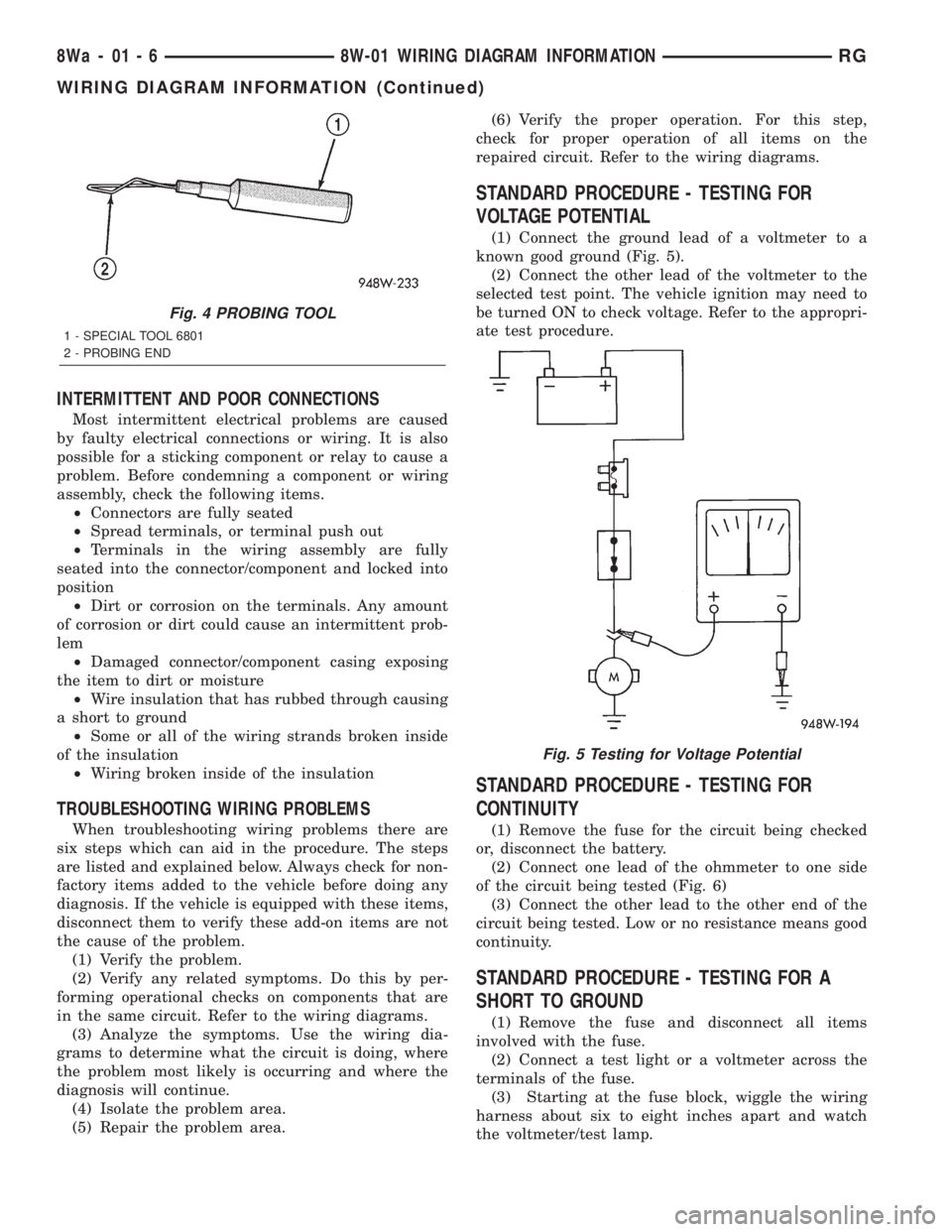
(1) Connect the ground lead of a voltmeter to a
known good ground (Fig. 5).
(2) Connect the other lead of the voltmeter to the
selected test point. The vehicle ignition may need to
be turned ON to check voltage. Refer to the appropri-
ate test procedure.
STANDARD PROCEDURE - TESTING FOR
CONTINUITY
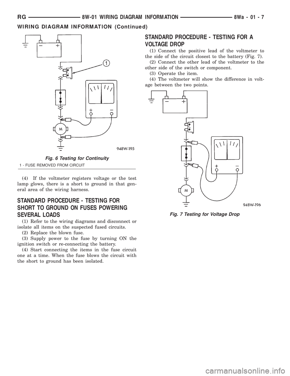
(1) Remove the fuse for the circuit being checked
or, disconnect the battery.
(2) Connect one lead of the ohmmeter to one side
of the circuit being tested (Fig. 6)
(3) Connect the other lead to the other end of the
circuit being tested. Low or no resistance means good
continuity.
STANDARD PROCEDURE - TESTING FOR A
SHORT TO GROUND
(1) Remove the fuse and disconnect all items
involved with the fuse.
(2) Connect a test light or a voltmeter across the
terminals of the fuse.
(3) Starting at the fuse block, wiggle the wiring
harness about six to eight inches apart and watch
the voltmeter/test lamp.
Fig. 4 PROBING TOOL
1 - SPECIAL TOOL 6801
2 - PROBING END
Fig. 5 Testing for Voltage Potential
8Wa - 01 - 6 8W-01 WIRING DIAGRAM INFORMATIONRG
WIRING DIAGRAM INFORMATION (Continued)
Page 2093 of 4284
(4) If the voltmeter registers voltage or the test
lamp glows, there is a short to ground in that gen-
eral area of the wiring harness.
STANDARD PROCEDURE - TESTING FOR
SHORT TO GROUND ON FUSES POWERING
SEVERAL LOADS
(1) Refer to the wiring diagrams and disconnect or
isolate all items on the suspected fused circuits.
(2) Replace the blown fuse.
(3) Supply power to the fuse by turning ON the
ignition switch or re-connecting the battery.
(4) Start connecting the items in the fuse circuit
one at a time. When the fuse blows the circuit with
the short to ground has been isolated.
STANDARD PROCEDURE - TESTING FOR A
VOLTAGE DROP
(1) Connect the positive lead of the voltmeter to
the side of the circuit closest to the battery (Fig. 7).
(2) Connect the other lead of the voltmeter to the
other side of the switch or component.
(3) Operate the item.
(4) The voltmeter will show the difference in volt-
age between the two points.
Fig. 6 Testing for Continuity
1 - FUSE REMOVED FROM CIRCUIT
Fig. 7 Testing for Voltage Drop
RG8W-01 WIRING DIAGRAM INFORMATION8Wa-01-7
WIRING DIAGRAM INFORMATION (Continued)
Page 3644 of 4284

OPERATION
The blower motor relay is an electromechanical
switch that uses a low current input from the Front
Control Module (FCM) to control the high current
output to the blower motor resistor (manual heater-
A/C control) or blower power module (ATC control).
The movable common feed contact point is held
against the fixed normally closed contact point by
spring pressure. When the relay coil is energized, an
electromagnetic field is produced by the coil wind-
ings. This electromagnetic field draws the movable
relay contact point away from the fixed normally
closed contact point, and holds it against the fixed
normally open contact point. When the relay coil is
de-energized, spring pressure returns the movable
contact point back against the fixed normally closed
contact point. The resistor or diode is connected in
parallel with the relay coil in the relay, and helps to
dissipate voltage spikes and electromagnetic interfer-
ence that can be generated as the electromagnetic
field of the relay coil collapses.
The blower motor relay terminals are connected to
the vehicle electrical system through a receptacle in
the Intelligent Power Module (IPM). The inputs and
outputs of the blower motor relay include:
²The common feed terminal (30) receives a bat-
tery current input from the battery through a B(+)
circuit at all times.
²The coil ground terminal (85) receives a ground
input through the front/rear blower motor relay con-
trol circuit only when the FCM electronically pulls
the control circuit to ground.
²The coil battery terminal (86) receives a battery
current input from the battery through a B(+) circuit
at all times.
²The normally open terminal (87) provides a bat-
tery current output to the blower motor resistor
(manual heater-A/C control) or blower power module
(automatic heater-A/C control) through a fuse in the
IPM on the fused front blower motor relay output cir-
cuit only when the blower motor relay coil is ener-
gized.
²The normally closed terminal (87A) is not con-
nected to any circuit in this application, but provides
a battery current output only when the blower motor
relay coil is de-energized.
Refer to the appropriate wiring information. The
wiring information includes wiring diagrams, proper
wire and connector repair procedures, further details
on wire harness routing and retention, as well as
pin-out and location views for the various wire har-
ness connectors, splices, and grounds.
DIAGNOSIS AND TESTING - BLOWER MOTOR
RELAY
The front blower motor relay (Fig. 7) is located in
the Intelligent Power Module (IPM), which is in the
engine compartment near the battery. See the fuse
and relay layout map molded into the inner surface
of the IPM cover for front blower motor relay identi-
fication and location. Remove the relay from the IPM
to perform the following tests:
(1) A relay in the de-energized position should
have continuity between terminals 87A and 30, and
no continuity between terminals 87 and 30. If OK, go
to Step 2. If not OK, replace the faulty relay.
(2) Resistance between terminals 85 and 86 (elec-
tromagnet) should be 7565 ohms. If OK, go to Step
3. If not OK, replace the faulty relay.
(3) Connect a battery to terminals 85 and 86.
There should now be continuity between terminals
30 and 87, and no continuity between terminals 87A
and 30. If OK, use a DRBIIItscan tool to perform
further diagnosis of the relay circuits. Refer to the
appropriate diagnostic information. If not OK,
replace the faulty relay.
REMOVAL
(1) Disconnect and isolate the battery negative
cable.
(2) Unlatch and remove the cover from the Intelli-
gent Power Module (IPM) (Fig. 8).
(3) See the fuse and relay layout map molded into
the inner surface of the IPM cover for front blower
motor relay identification and location.
(4) Remove the front blower motor relay from the
IPM by pulling the relay straight up.
INSTALLATION
(1) See the fuse and relay layout map molded into
the inner surface of the Intelligent Power Module
(IPM) cover for front blower motor relay identifica-
tion and location.
(2) Position the front blower motor relay to the
proper receptacle in the IPM.
(3) Align the front blower motor relay terminals
with the terminal cavities in the IPM relay recepta-
cle.
(4) Push down firmly on the front blower motor
relay until the terminals are fully seated in the ter-
minal cavities in the IPM receptacle.
(5) Install and latch the cover onto the IPM.
(6) Reconnect the battery negative cable.
24 - 14 CONTROLS - FRONTRS
BLOWER MOTOR RELAY (Continued)
Page 3652 of 4284
cover for compressor clutch relay identification and
location.
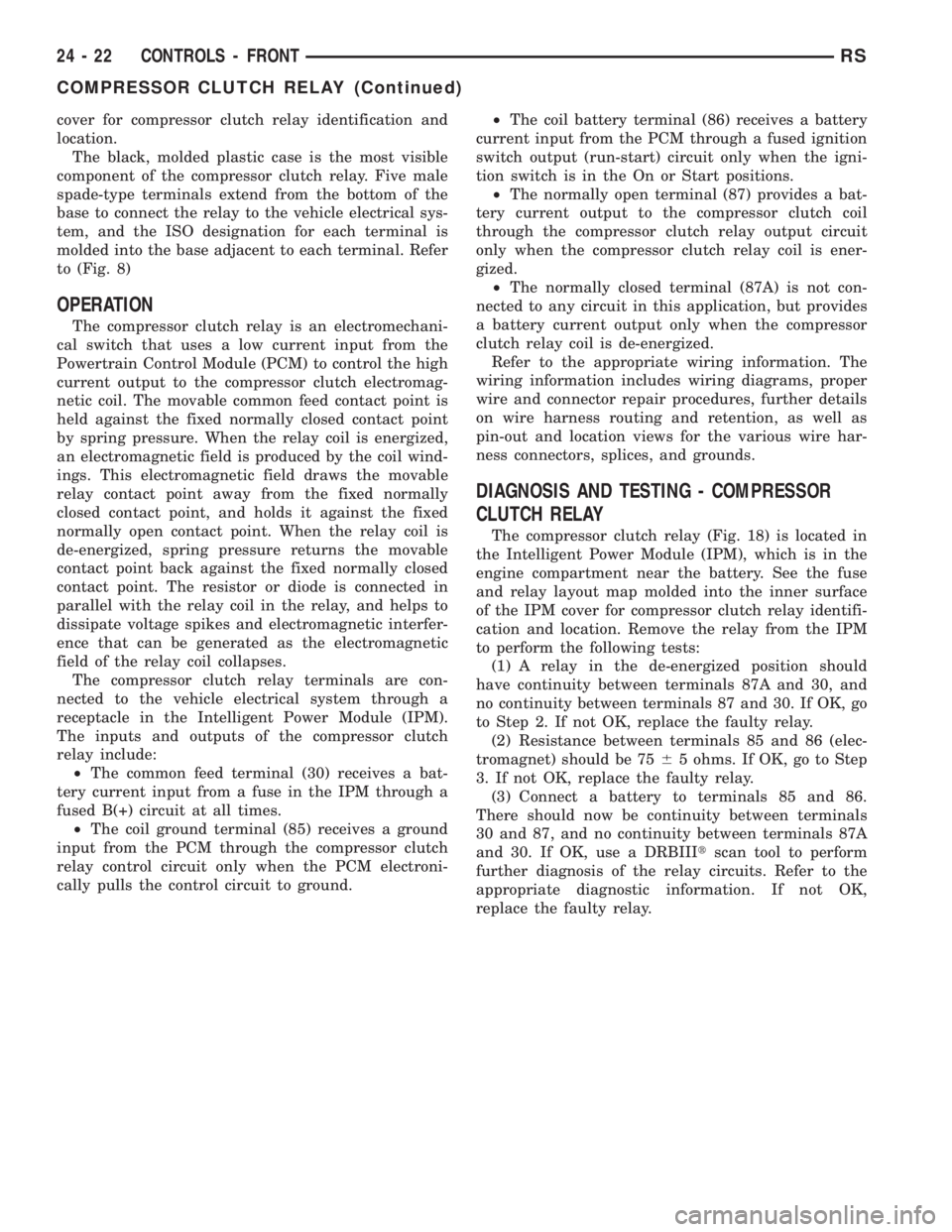
The black, molded plastic case is the most visible
component of the compressor clutch relay. Five male
spade-type terminals extend from the bottom of the
base to connect the relay to the vehicle electrical sys-
tem, and the ISO designation for each terminal is
molded into the base adjacent to each terminal. Refer
to (Fig. 8)
OPERATION
The compressor clutch relay is an electromechani-
cal switch that uses a low current input from the
Powertrain Control Module (PCM) to control the high
current output to the compressor clutch electromag-
netic coil. The movable common feed contact point is
held against the fixed normally closed contact point
by spring pressure. When the relay coil is energized,
an electromagnetic field is produced by the coil wind-
ings. This electromagnetic field draws the movable
relay contact point away from the fixed normally
closed contact point, and holds it against the fixed
normally open contact point. When the relay coil is
de-energized, spring pressure returns the movable
contact point back against the fixed normally closed
contact point. The resistor or diode is connected in
parallel with the relay coil in the relay, and helps to
dissipate voltage spikes and electromagnetic interfer-
ence that can be generated as the electromagnetic
field of the relay coil collapses.
The compressor clutch relay terminals are con-
nected to the vehicle electrical system through a
receptacle in the Intelligent Power Module (IPM).
The inputs and outputs of the compressor clutch
relay include:
²The common feed terminal (30) receives a bat-
tery current input from a fuse in the IPM through a
fused B(+) circuit at all times.
²The coil ground terminal (85) receives a ground
input from the PCM through the compressor clutch
relay control circuit only when the PCM electroni-
cally pulls the control circuit to ground.²The coil battery terminal (86) receives a battery
current input from the PCM through a fused ignition
switch output (run-start) circuit only when the igni-
tion switch is in the On or Start positions.
²The normally open terminal (87) provides a bat-
tery current output to the compressor clutch coil
through the compressor clutch relay output circuit
only when the compressor clutch relay coil is ener-
gized.
²The normally closed terminal (87A) is not con-
nected to any circuit in this application, but provides
a battery current output only when the compressor
clutch relay coil is de-energized.
Refer to the appropriate wiring information. The
wiring information includes wiring diagrams, proper
wire and connector repair procedures, further details
on wire harness routing and retention, as well as
pin-out and location views for the various wire har-
ness connectors, splices, and grounds.
DIAGNOSIS AND TESTING - COMPRESSOR
CLUTCH RELAY
The compressor clutch relay (Fig. 18) is located in
the Intelligent Power Module (IPM), which is in the
engine compartment near the battery. See the fuse
and relay layout map molded into the inner surface
of the IPM cover for compressor clutch relay identifi-
cation and location. Remove the relay from the IPM
to perform the following tests:
(1) A relay in the de-energized position should
have continuity between terminals 87A and 30, and
no continuity between terminals 87 and 30. If OK, go
to Step 2. If not OK, replace the faulty relay.
(2) Resistance between terminals 85 and 86 (elec-
tromagnet) should be 7565 ohms. If OK, go to Step
3. If not OK, replace the faulty relay.
(3) Connect a battery to terminals 85 and 86.
There should now be continuity between terminals
30 and 87, and no continuity between terminals 87A
and 30. If OK, use a DRBIIItscan tool to perform
further diagnosis of the relay circuits. Refer to the
appropriate diagnostic information. If not OK,
replace the faulty relay.
24 - 22 CONTROLS - FRONTRS
COMPRESSOR CLUTCH RELAY (Continued)
Page 3664 of 4284
The blower motor relay terminals are connected to
the vehicle electrical system through a receptacle in
the Intelligent Power Module (IPM). The inputs and
outputs of the compressor clutch relay include:
²The common feed terminal (30) receives a bat-
tery current input from the battery through a B(+)
circuit at all times.
²The coil ground terminal (85) receives a ground
input through the front/rear blower motor relay con-
trol circuit only when the FCM electronically pulls
the control circuit to ground.
²The coil battery terminal (86) receives a battery
current input from the battery through a B(+) circuit
at all times.
²The normally open terminal (87) provides a bat-
tery current output to the blower motor resistor
(manual heater-A/C control) or blower power module
(automatic heater-A/C control) through a fuse in the
IPM on the fused rear blower motor relay output cir-
cuit only when the blower motor relay coil is ener-
gized.
²The normally closed terminal (87A) is not con-
nected to any circuit in this application, but provides
a battery current output only when the blower motor
relay coil is de-energized.
Refer to the appropriate wiring information. The
wiring information includes wiring diagrams, proper
wire and connector repair procedures, further details
on wire harness routing and retention, as well as
pin-out and location views for the various wire har-
ness connectors, splices, and grounds.
DIAGNOSIS AND TESTING - BLOWER MOTOR
RELAY
The rear blower motor relay (Fig. 5) is located in
the Intelligent Power Module (IPM), which is in the
engine compartment near the battery. See the fuse
and relay layout map molded into the inner surface
of the IPM cover for rear blower motor relay identi-
fication and location. Remove the relay from the IPM
to perform the following tests:
(1) A relay in the de-energized position should
have continuity between terminals 87A and 30, and
no continuity between terminals 87 and 30. If OK, go
to Step 2. If not OK, replace the faulty relay.
(2) Resistance between terminals 85 and 86 (elec-
tromagnet) should be 7565 ohms. If OK, go to Step
3. If not OK, replace the faulty relay.
(3) Connect a battery to terminals 85 and 86.
There should now be continuity between terminals
30 and 87, and no continuity between terminals 87A
and 30. If OK, use a DRBIIItscan tool to perform
further diagnosis of the relay circuits. Refer to the
appropriate diagnostic information. If not OK,
replace the faulty relay.
REMOVAL
(1) Disconnect and isolate the battery negative
cable.
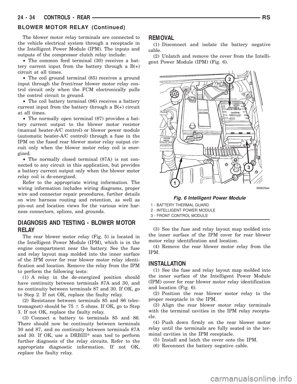
(2) Unlatch and remove the cover from the Intelli-
gent Power Module (IPM) (Fig. 6).
(3) See the fuse and relay layout map molded into
the inner surface of the IPM cover for rear blower
motor relay identification and location.
(4) Remove the rear blower motor relay from the
IPM.
INSTALLATION
(1) See the fuse and relay layout map molded into
the inner surface of the Intelligent Power Module
(IPM) cover for rear blower motor relay identification
and location (Fig. 6).
(2) Position the rear blower motor relay to the
proper receptacle in the IPM.
(3) Align the rear blower motor relay terminals
with the terminal cavities in the IPM relay recepta-
cle.
(4) Push down firmly on the rear blower motor
relay until the terminals are fully seated in the ter-
minal cavities in the IPM receptacle.
(5) Install and latch the cover onto the IPM.
(6) Reconnect the battery negative cable.
Fig. 6 Intelligent Power Module
1 - BATTERY THERMAL GUARD
2 - INTELLIGENT POWER MODULE
3 - FRONT CONTROL MODULE
24 - 34 CONTROLS - REARRS
BLOWER MOTOR RELAY (Continued)
Page 3793 of 4284
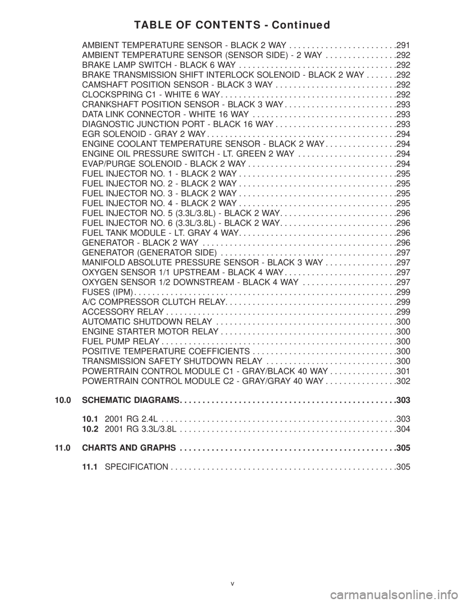
TABLE OF CONTENTS - Continued
AMBIENT TEMPERATURE SENSOR - BLACK 2 WAY........................291
AMBIENT TEMPERATURE SENSOR (SENSOR SIDE)-2WAY................292
BRAKE LAMP SWITCH - BLACK 6 WAY...................................292
BRAKE TRANSMISSION SHIFT INTERLOCK SOLENOID - BLACK 2 WAY.......292
CAMSHAFT POSITION SENSOR - BLACK 3 WAY...........................292
CLOCKSPRING C1 - WHITE 6 WAY.......................................292
CRANKSHAFT POSITION SENSOR - BLACK 3 WAY.........................293
DATA LINK CONNECTOR - WHITE 16 WAY................................293
DIAGNOSTIC JUNCTION PORT - BLACK 16 WAY...........................293
EGR SOLENOID - GRAY 2 WAY..........................................294
ENGINE COOLANT TEMPERATURE SENSOR - BLACK 2 WAY................294
ENGINE OIL PRESSURE SWITCH - LT. GREEN 2 WAY......................294
EVAP/PURGE SOLENOID - BLACK 2 WAY.................................294
FUEL INJECTOR NO. 1 - BLACK 2 WAY...................................295
FUEL INJECTOR NO. 2 - BLACK 2 WAY...................................295
FUEL INJECTOR NO. 3 - BLACK 2 WAY...................................295
FUEL INJECTOR NO. 4 - BLACK 2 WAY...................................295
FUEL INJECTOR NO. 5 (3.3L/3.8L) - BLACK 2 WAY..........................296
FUEL INJECTOR NO. 6 (3.3L/3.8L) - BLACK 2 WAY..........................296
FUEL TANK MODULE - LT. GRAY 4 WAY...................................296
GENERATOR - BLACK 2 WAY...........................................296
GENERATOR (GENERATOR SIDE).......................................297
MANIFOLD ABSOLUTE PRESSURE SENSOR - BLACK 3 WAY................297
OXYGEN SENSOR 1/1 UPSTREAM - BLACK 4 WAY.........................297
OXYGEN SENSOR 1/2 DOWNSTREAM - BLACK 4 WAY.....................297
FUSES (IPM)..........................................................299
A/C COMPRESSOR CLUTCH RELAY......................................299
ACCESSORY RELAY...................................................299
AUTOMATIC SHUTDOWN RELAY........................................300
ENGINE STARTER MOTOR RELAY.......................................300
FUEL PUMP RELAY....................................................300
POSITIVE TEMPERATURE COEFFICIENTS................................300
TRANSMISSION SAFETY SHUTDOWN RELAY.............................300
POWERTRAIN CONTROL MODULE C1 - GRAY/BLACK 40 WAY...............301
POWERTRAIN CONTROL MODULE C2 - GRAY/GRAY 40 WAY................302
10.0 SCHEMATIC DIAGRAMS................................................303
10.12001 RG 2.4L....................................................303
10.22001 RG 3.3L/3.8L................................................304
11.0 CHARTS AND GRAPHS................................................305
11.1SPECIFICATION..................................................305
v
Page 4048 of 4284
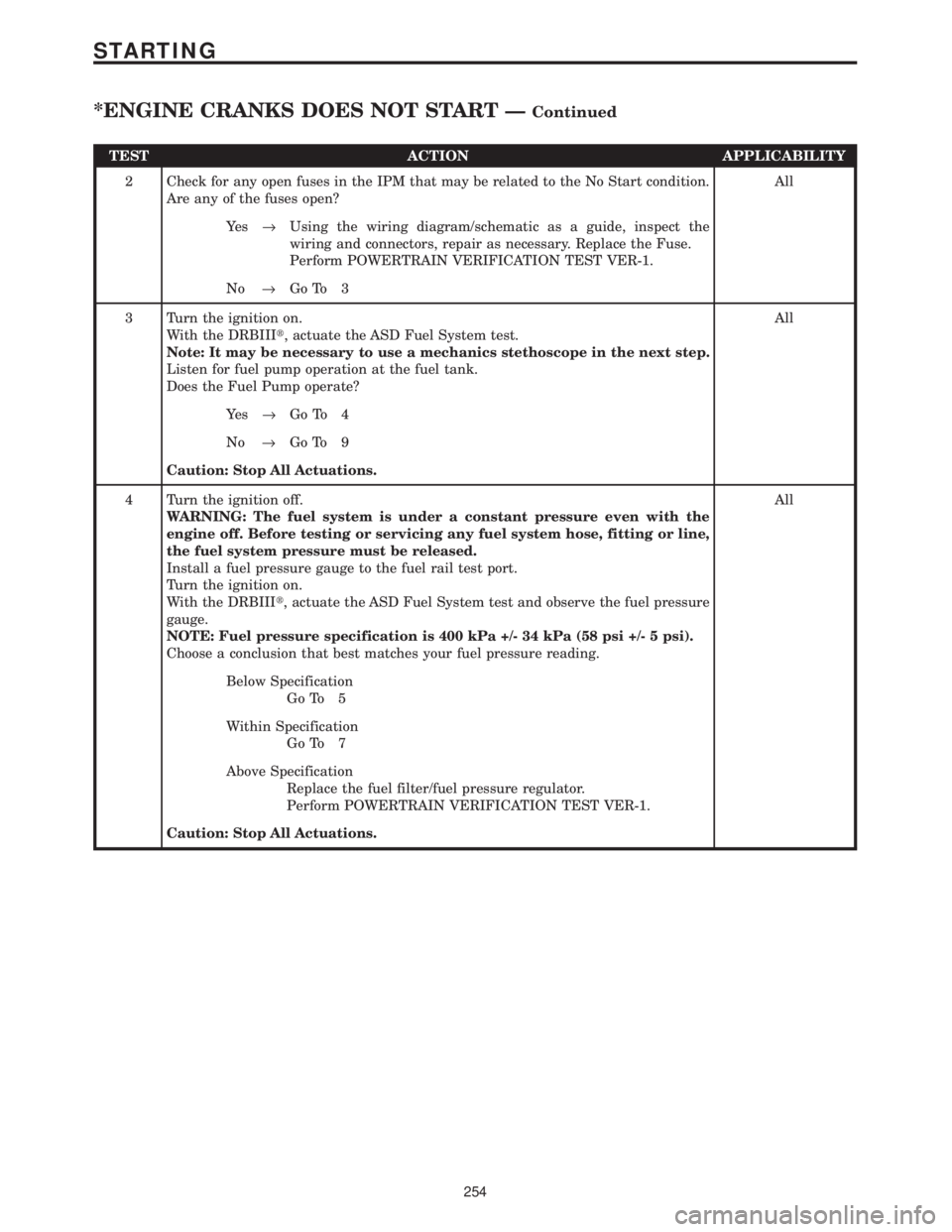
TEST ACTION APPLICABILITY
2 Check for any open fuses in the IPM that may be related to the No Start condition.
Are any of the fuses open?All
Ye s®Using the wiring diagram/schematic as a guide, inspect the
wiring and connectors, repair as necessary. Replace the Fuse.
Perform POWERTRAIN VERIFICATION TEST VER-1.
No®Go To 3
3 Turn the ignition on.
With the DRBIIIt, actuate the ASD Fuel System test.
Note: It may be necessary to use a mechanics stethoscope in the next step.
Listen for fuel pump operation at the fuel tank.
Does the Fuel Pump operate?All
Ye s®Go To 4
No®Go To 9
Caution: Stop All Actuations.
4 Turn the ignition off.
WARNING: The fuel system is under a constant pressure even with the
engine off. Before testing or servicing any fuel system hose, fitting or line,
the fuel system pressure must be released.
Install a fuel pressure gauge to the fuel rail test port.
Turn the ignition on.
With the DRBIIIt, actuate the ASD Fuel System test and observe the fuel pressure
gauge.
NOTE: Fuel pressure specification is 400 kPa +/- 34 kPa (58 psi +/- 5 psi).
Choose a conclusion that best matches your fuel pressure reading.All
Below Specification
Go To 5
Within Specification
Go To 7
Above Specification
Replace the fuel filter/fuel pressure regulator.
Perform POWERTRAIN VERIFICATION TEST VER-1.
Caution: Stop All Actuations.
254
STARTING
*ENGINE CRANKS DOES NOT START ÐContinued
Page 4103 of 4284
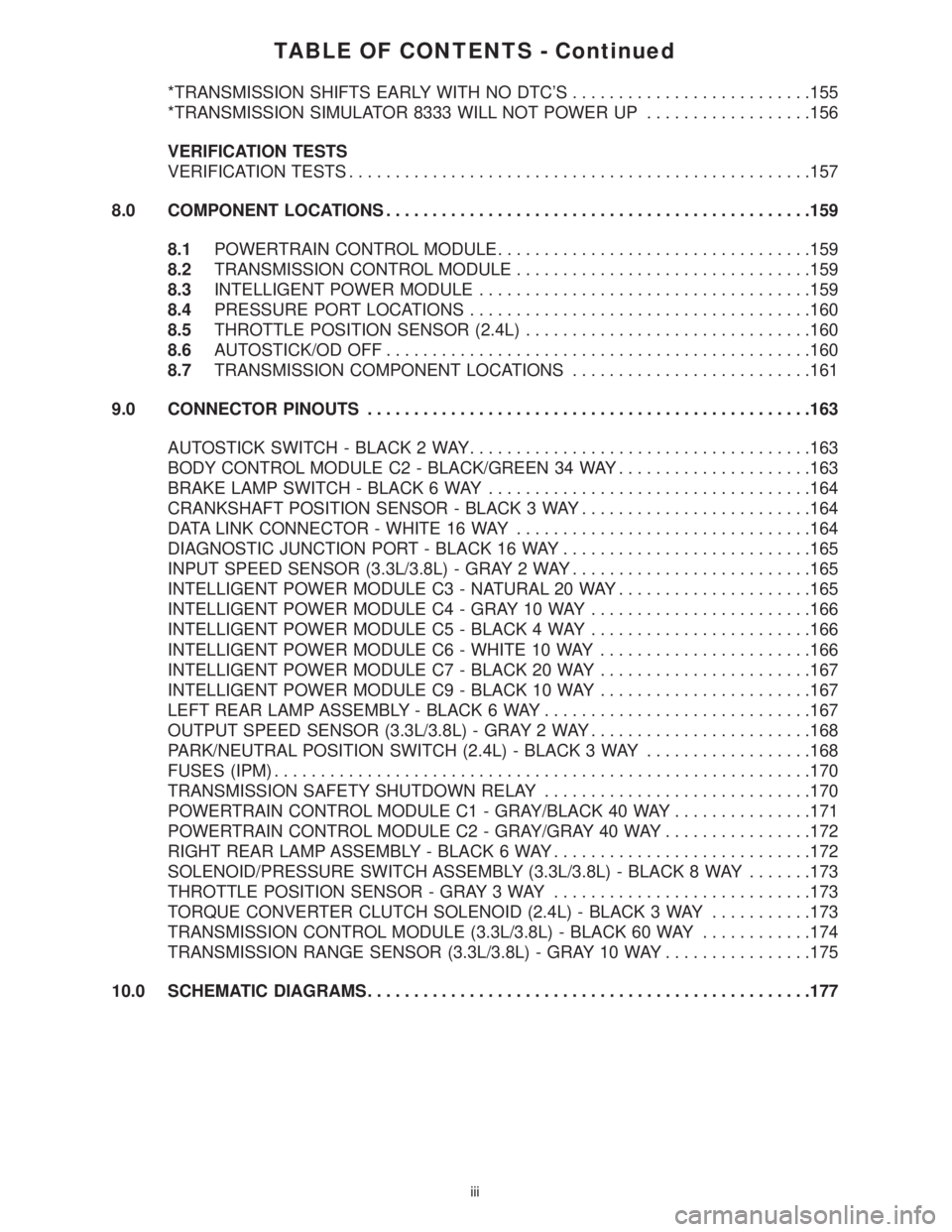
TABLE OF CONTENTS - Continued
*TRANSMISSION SHIFTS EARLY WITH NO DTC'S..........................155
*TRANSMISSION SIMULATOR 8333 WILL NOT POWER UP..................156
VERIFICATION TESTS
VERIFICATION TESTS..................................................157
8.0 COMPONENT LOCATIONS..............................................159
8.1POWERTRAIN CONTROL MODULE..................................159
8.2TRANSMISSION CONTROL MODULE................................159
8.3INTELLIGENT POWER MODULE....................................159
8.4PRESSURE PORT LOCATIONS.....................................160
8.5THROTTLE POSITION SENSOR (2.4L)...............................160
8.6AUTOSTICK/OD OFF..............................................160
8.7TRANSMISSION COMPONENT LOCATIONS..........................161
9.0 CONNECTOR PINOUTS................................................163
AUTOSTICK SWITCH - BLACK 2 WAY.....................................163
BODY CONTROL MODULE C2 - BLACK/GREEN 34 WAY.....................163
BRAKE LAMP SWITCH - BLACK 6 WAY...................................164
CRANKSHAFT POSITION SENSOR - BLACK 3 WAY.........................164
DATA LINK CONNECTOR - WHITE 16 WAY................................164
DIAGNOSTIC JUNCTION PORT - BLACK 16 WAY...........................165
INPUT SPEED SENSOR (3.3L/3.8L) - GRAY 2 WAY..........................165
INTELLIGENT POWER MODULE C3 - NATURAL 20 WAY.....................165
INTELLIGENT POWER MODULE C4 - GRAY 10 WAY........................166
INTELLIGENT POWER MODULE C5 - BLACK 4 WAY........................166
INTELLIGENT POWER MODULE C6 - WHITE 10 WAY.......................166
INTELLIGENT POWER MODULE C7 - BLACK 20 WAY.......................167
INTELLIGENT POWER MODULE C9 - BLACK 10 WAY.......................167
LEFT REAR LAMP ASSEMBLY - BLACK 6 WAY.............................167
OUTPUT SPEED SENSOR (3.3L/3.8L) - GRAY 2 WAY........................168
PARK/NEUTRAL POSITION SWITCH (2.4L) - BLACK 3 WAY..................168
FUSES (IPM)..........................................................170
TRANSMISSION SAFETY SHUTDOWN RELAY.............................170
POWERTRAIN CONTROL MODULE C1 - GRAY/BLACK 40 WAY...............171
POWERTRAIN CONTROL MODULE C2 - GRAY/GRAY 40 WAY................172
RIGHT REAR LAMP ASSEMBLY - BLACK 6 WAY............................172
SOLENOID/PRESSURE SWITCH ASSEMBLY (3.3L/3.8L) - BLACK 8 WAY.......173
THROTTLE POSITION SENSOR - GRAY 3 WAY............................173
TORQUE CONVERTER CLUTCH SOLENOID (2.4L) - BLACK 3 WAY...........173
TRANSMISSION CONTROL MODULE (3.3L/3.8L) - BLACK 60 WAY............174
TRANSMISSION RANGE SENSOR (3.3L/3.8L) - GRAY 10 WAY................175
10.0 SCHEMATIC DIAGRAMS................................................177
iii