Page 1594 of 4284
SPECIFICATIONS
SPECIFICATIONS - HALF SHAFT - FRONT
TORQUE SPECIFICATIONS
DESCRIPTION N´m Ft. Lbs. In. Lbs.
Nut, Hub 244 180 -
Nuts, Rear Wheel Lug 135 100 -
Bolt, Half Shaft to Output Flange 61 45 -
CV BOOT - INNER/OUTER
REMOVAL
(1) Remove half shaft from vehicle. (Refer to 3 -
DIFFERENTIAL & DRIVELINE/HALF SHAFT -
REMOVAL)
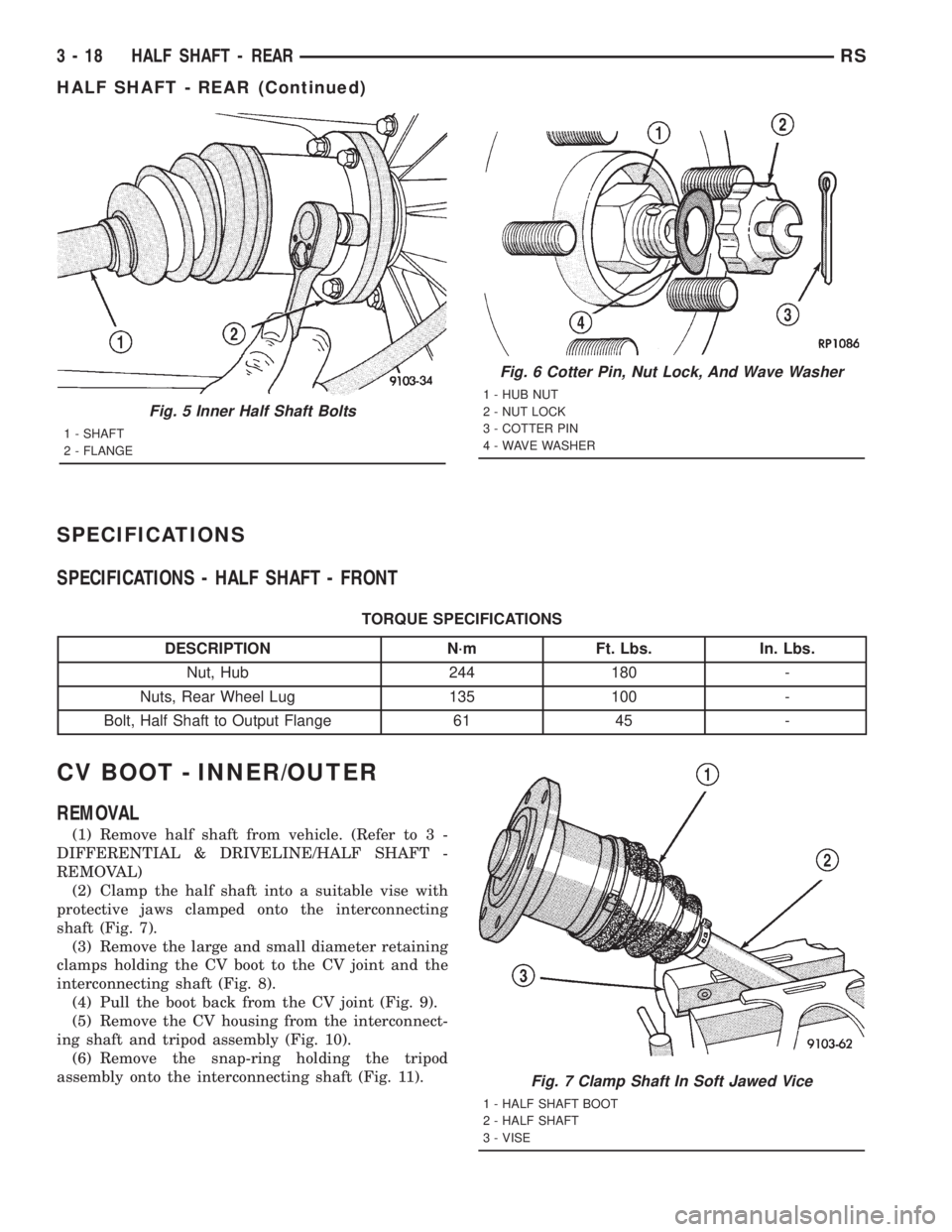
(2) Clamp the half shaft into a suitable vise with
protective jaws clamped onto the interconnecting
shaft (Fig. 7).
(3) Remove the large and small diameter retaining
clamps holding the CV boot to the CV joint and the
interconnecting shaft (Fig. 8).
(4) Pull the boot back from the CV joint (Fig. 9).
(5) Remove the CV housing from the interconnect-
ing shaft and tripod assembly (Fig. 10).
(6) Remove the snap-ring holding the tripod
assembly onto the interconnecting shaft (Fig. 11).
Fig. 5 Inner Half Shaft Bolts
1 - SHAFT
2 - FLANGE
Fig. 6 Cotter Pin, Nut Lock, And Wave Washer
1 - HUB NUT
2 - NUT LOCK
3 - COTTER PIN
4 - WAVE WASHER
Fig. 7 Clamp Shaft In Soft Jawed Vice
1 - HALF SHAFT BOOT
2 - HALF SHAFT
3 - VISE
3 - 18 HALF SHAFT - REARRS
HALF SHAFT - REAR (Continued)
Page 1595 of 4284
(7) Remove the tripod assembly from the intercon-
necting shaft (Fig. 12).
(8) Remove the CV boot from the interconnecting
shaft (Fig. 13).
Fig. 8 Remove Boot Clamps
1 - HALF SHAFT BOOT
2 - CLAMP
Fig. 9 Pull Back Boot
1 - HALF SHAFT BOOT
2 - HALF SHAFT JOINT
Fig. 10 Remove CV Housing
1 - HALF SHAFT JOINT HOUSING
2 - BOOT
Fig. 11 Remove Snap-Ring
1 - SNAP-RING
2 - HALF SHAFT BOOT
3 - TRIPOD ASSEMBLY
4 - SNAP-RING PLIERS
RSHALF SHAFT - REAR3-19
CV BOOT - INNER/OUTER (Continued)
Page 1596 of 4284
INSTALLATION
(1) Clean the interconnecting shaft and inner CV
joint of any residual grease and dirt.
(2) Slide the new small diameter retaining clamp
onto the interconnecting shaft.
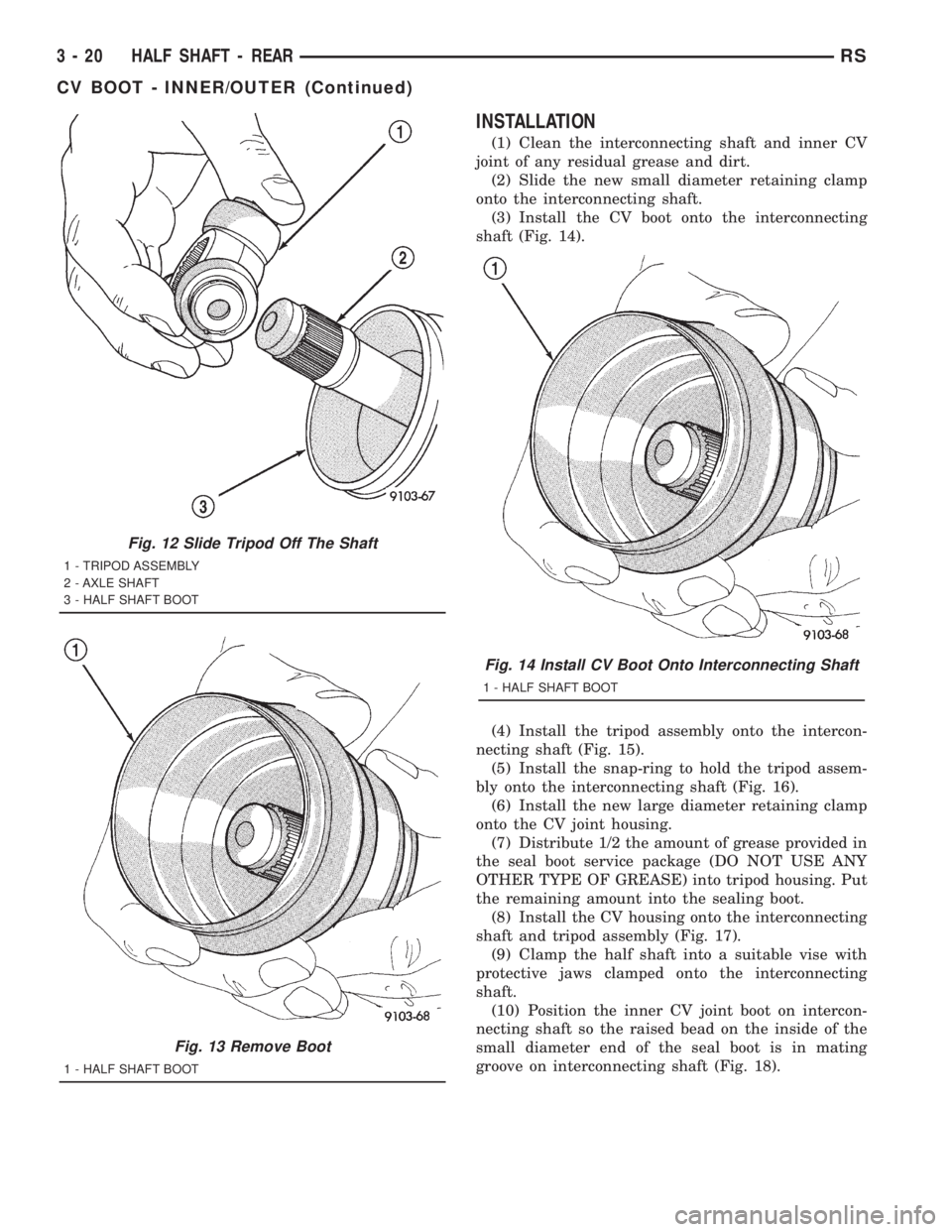
(3) Install the CV boot onto the interconnecting
shaft (Fig. 14).
(4) Install the tripod assembly onto the intercon-
necting shaft (Fig. 15).
(5) Install the snap-ring to hold the tripod assem-
bly onto the interconnecting shaft (Fig. 16).
(6) Install the new large diameter retaining clamp
onto the CV joint housing.
(7) Distribute 1/2 the amount of grease provided in
the seal boot service package (DO NOT USE ANY
OTHER TYPE OF GREASE) into tripod housing. Put
the remaining amount into the sealing boot.
(8) Install the CV housing onto the interconnecting
shaft and tripod assembly (Fig. 17).
(9) Clamp the half shaft into a suitable vise with
protective jaws clamped onto the interconnecting
shaft.
(10) Position the inner CV joint boot on intercon-
necting shaft so the raised bead on the inside of the
small diameter end of the seal boot is in mating
groove on interconnecting shaft (Fig. 18).
Fig. 12 Slide Tripod Off The Shaft
1 - TRIPOD ASSEMBLY
2 - AXLE SHAFT
3 - HALF SHAFT BOOT
Fig. 13 Remove Boot
1 - HALF SHAFT BOOT
Fig. 14 Install CV Boot Onto Interconnecting Shaft
1 - HALF SHAFT BOOT
3 - 20 HALF SHAFT - REARRS
CV BOOT - INNER/OUTER (Continued)
Page 1597 of 4284
(11) Install inner CV joint seal boot to intercon-
necting shaft clamp evenly on sealing boot.
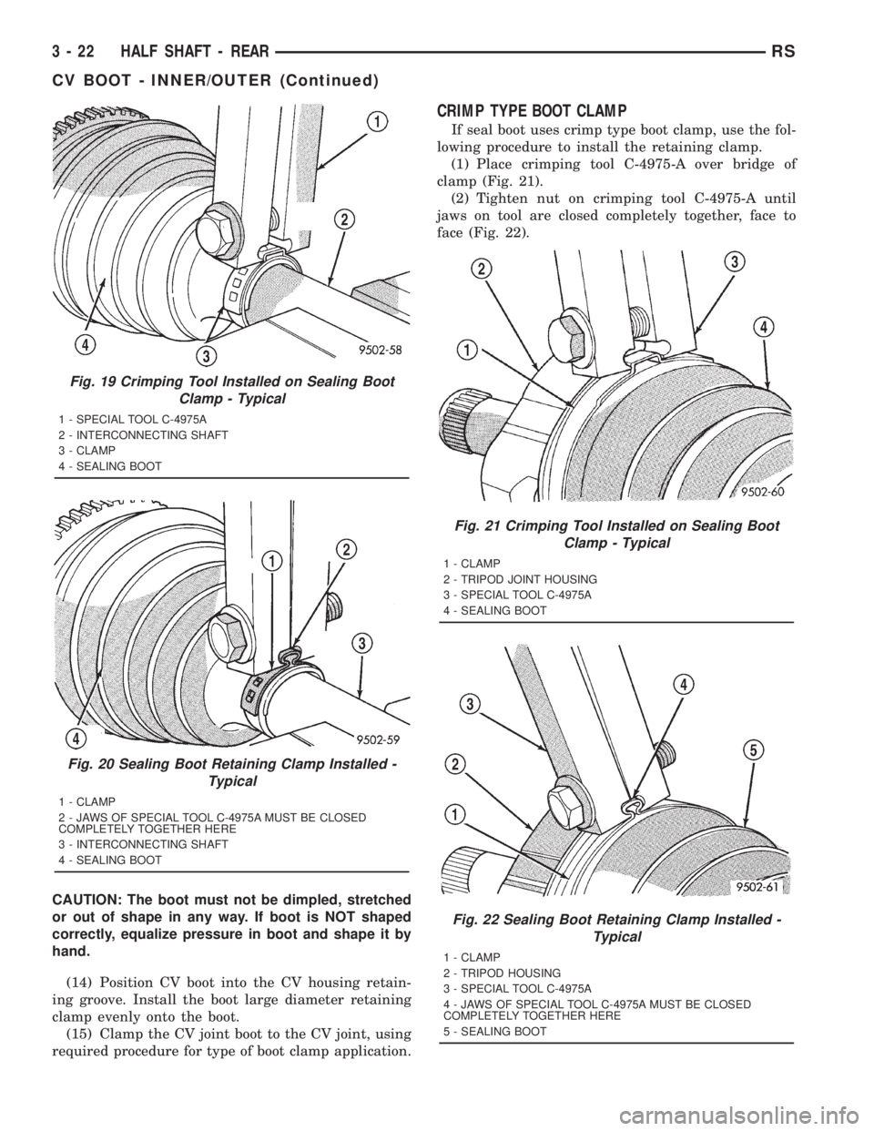
(12) Place crimping tool C-4975-A over bridge of
clamp (Fig. 19).
(13) Tighten nut on crimping tool C-4975-A until
jaws on tool are closed completely together, face to
face (Fig. 20).
Fig. 15 Slide Tripod Onto The Interconnecting Shaft
1 - TRIPOD ASSEMBLY
2 - AXLE SHAFT
3 - HALF SHAFT BOOT
Fig. 16 Install Snap-Ring
1 - SNAP-RING
2 - HALF SHAFT BOOT
3 - TRIPOD ASSEMBLY
4 - SNAP-RING PLIERS
Fig. 17 Install CV Housing
1 - HALF SHAFT JOINT HOUSING
2 - BOOT
Fig. 18 Sealing Boot Installation on Interconnecting
Shaft
1 - SEALING BOOT
2 - RAISED BEAD IN THIS AREA OF SEALING BOOT
3 - GROOVE
4 - INTERCONNECTING SHAFT
RSHALF SHAFT - REAR3-21
CV BOOT - INNER/OUTER (Continued)
Page 1598 of 4284
CAUTION: The boot must not be dimpled, stretched
or out of shape in any way. If boot is NOT shaped
correctly, equalize pressure in boot and shape it by
hand.
(14) Position CV boot into the CV housing retain-
ing groove. Install the boot large diameter retaining
clamp evenly onto the boot.
(15) Clamp the CV joint boot to the CV joint, using
required procedure for type of boot clamp application.
CRIMP TYPE BOOT CLAMP
If seal boot uses crimp type boot clamp, use the fol-
lowing procedure to install the retaining clamp.
(1) Place crimping tool C-4975-A over bridge of
clamp (Fig. 21).
(2) Tighten nut on crimping tool C-4975-A until
jaws on tool are closed completely together, face to
face (Fig. 22).
Fig. 19 Crimping Tool Installed on Sealing Boot
Clamp - Typical
1 - SPECIAL TOOL C-4975A
2 - INTERCONNECTING SHAFT
3 - CLAMP
4 - SEALING BOOT
Fig. 20 Sealing Boot Retaining Clamp Installed -
Typical
1 - CLAMP
2 - JAWS OF SPECIAL TOOL C-4975A MUST BE CLOSED
COMPLETELY TOGETHER HERE
3 - INTERCONNECTING SHAFT
4 - SEALING BOOT
Fig. 21 Crimping Tool Installed on Sealing Boot
Clamp - Typical
1 - CLAMP
2 - TRIPOD JOINT HOUSING
3 - SPECIAL TOOL C-4975A
4 - SEALING BOOT
Fig. 22 Sealing Boot Retaining Clamp Installed -
Typical
1 - CLAMP
2 - TRIPOD HOUSING
3 - SPECIAL TOOL C-4975A
4 - JAWS OF SPECIAL TOOL C-4975A MUST BE CLOSED
COMPLETELY TOGETHER HERE
5 - SEALING BOOT
3 - 22 HALF SHAFT - REARRS
CV BOOT - INNER/OUTER (Continued)
Page 1599 of 4284
LATCHING TYPE BOOT CLAMP
If seal boot uses low profile latching type boot
clamp, use the following procedure to install the
retaining clamp.
(1) Place prongs of clamp locking tool in the holes
of the clamp (Fig. 23).
(2) Squeeze tool together until top band of clamp is
latched behind the two tabs on lower band of clamp
(Fig. 24).
(3) Install the half shaft into the vehicle. (Refer to
3 - DIFFERENTIAL & DRIVELINE/HALF SHAFT -
INSTALLATION)
Fig. 23 Clamping Tool Installed on Sealing Boot
Clamp
1 - CLAMP
2 - SPECIAL TOOL YA3050
3 - SEALING BOOT
Fig. 24 Sealing Boot Clamp Correctly Installed
1 - INNER TRIPOD JOINT HOUSING
2 - TOP BAND OF CLAMP MUST BE RETAINED BY TABS AS
SHOWN HERE TO CORRECTLY LATCH BOOT CLAMP
3 - SEALING BOOT
RSHALF SHAFT - REAR3-23
CV BOOT - INNER/OUTER (Continued)
Page 1635 of 4284
BRAKE FLUID LEVEL SWITCH
DESCRIPTION
The brake fluid level switch is located in the brake
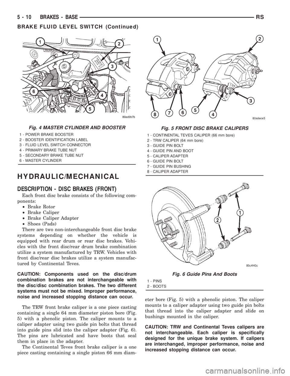
fluid reservoir of the master cylinder (Fig. 4).
OPERATION
The purpose of the brake fluid level switch is to
provide the driver with an early warning that the
brake fluid level in the master cylinder fluid reser-
voir has dropped below a normal level. This may
indicate:
²Abnormal loss of brake fluid in the master cyl-
inder fluid reservoir resulting from a leak in the
hydraulic system.
²Brake shoe linings which have worn to a point
requiring replacement.
As the brake fluid drops below the minimum level,
the brake fluid level switch closes to complete the red
BRAKE warning indicator (lamp) circuit. This will
turn on the red BRAKE warning indicator. The mas-
ter cylinder fluid reservoir should be checked and
refilled to the Full mark with DOT 3 brake fluid.If
the brake fluid level has dropped below the add
line in the master cylinder fluid reservoir, the
entire brake hydraulic system should be
checked for evidence of a leak.
REMOVAL
(1) Remove wiring harness connector from brake
fluid reservoir level switch (Fig. 4).
(2) Using fingers, compress the retaining tabs on
the opposite end of brake fluid level switch.
(3) With retaining tabs compressed, grasp the con-
nector end of brake fluid level switch and pull it out
of master cylinder brake fluid reservoir.
INSTALLATION
(1) Insert brake fluid level switch into left side of
brake fluid reservoir. Be sure switch is pushed in
until retaining tabs lock it to brake fluid reservoir.
(2) Connect vehicle wiring harness connector to
brake fluid level switch (Fig. 4).
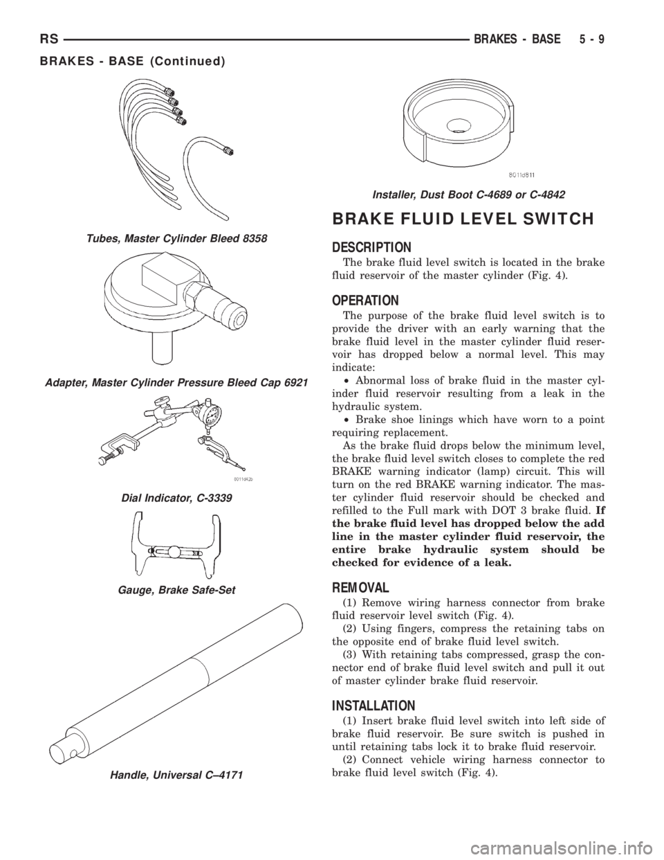
Tubes, Master Cylinder Bleed 8358
Adapter, Master Cylinder Pressure Bleed Cap 6921
Dial Indicator, C-3339
Gauge, Brake Safe-Set
Handle, Universal C±4171
Installer, Dust Boot C-4689 or C-4842
RSBRAKES - BASE5-9
BRAKES - BASE (Continued)
Page 1636 of 4284
HYDRAULIC/MECHANICAL
DESCRIPTION - DISC BRAKES (FRONT)
Each front disc brake consists of the following com-
ponents:
²Brake Rotor
²Brake Caliper
²Brake Caliper Adapter
²Shoes (Pads)
There are two non-interchangeable front disc brake
systems depending on whether the vehicle is
equipped with rear drum or rear disc brakes. Vehi-
cles with the front disc/rear drum brake combination
utilize a system manufactured by TRW. Vehicles with
front disc/rear disc brakes utilize a system manufac-
tured by Continental Teves.
CAUTION: Components used on the disc/drum
combination brakes are not interchangeable with
the disc/disc combination brakes. The two different
systems must not be mixed. Improper performance,
noise and increased stopping distance can occur.
The TRW front brake caliper is a one piece casting
containing a single 64 mm diameter piston bore (Fig.
5) with a phenolic piston. The caliper mounts to a
caliper adapter using two guide pin bolts that thread
into guide pins slid into the caliper adapter (Fig. 6).
The pins are lubricated and have boots that seal
them in place in the adapter.
The Continental Teves front brake caliper is a one
piece casting containing a single piston 66 mm diam-eter bore (Fig. 5) with a phenolic piston. The caliper
mounts to a caliper adapter using two guide pin bolts
that thread into the caliper adapter and slide on
bushings mounted in the caliper.
CAUTION: TRW and Continental Teves calipers are
not interchangeable. Each caliper is specifically
designed for the unique brake system. If calipers
are interchanged, improper performance, noise and
increased stopping distance can occur.
Fig. 4 MASTER CYLINDER AND BOOSTER
1 - POWER BRAKE BOOSTER
2 - BOOSTER IDENTIFICATION LABEL
3 - FLUID LEVEL SWITCH CONNECTOR
4 - PRIMARY BRAKE TUBE NUT
5 - SECONDARY BRAKE TUBE NUT
6 - MASTER CYLINDER
Fig. 5 FRONT DISC BRAKE CALIPERS
1 - CONTINENTAL TEVES CALIPER (66 mm bore)
2 - TRW CALIPER (64 mm bore)
3 - GUIDE PIN BOLT
4 - GUIDE PIN AND BOOT
5 - CALIPER ADAPTER
6 - GUIDE PIN BOLT
7 - GUIDE PIN BUSHING
8 - CALIPER ADAPTER
Fig. 6 Guide Pins And Boots
1 - PINS
2 - BOOTS
5 - 10 BRAKES - BASERS
BRAKE FLUID LEVEL SWITCH (Continued)