2001 CHRYSLER VOYAGER maintenance schedule
[x] Cancel search: maintenance schedulePage 2874 of 4284
The fuel filter is replaceable, it is mounted on the
outside and on top of the fuel tank. Refer to the
Maintenance Schedules in the Introduction section of
this manual for recommended fuel filter replacement
intervals.
FFV REPLACEMENT PARTS
Many components in a Flexible Fuel Vehicle (FFV)
are designed to be compatible with ethanol. Always
be sure that the vehicle is serviced with correct etha-
nol compatible parts.
CAUTION: Replacing fuel system components with
non-ethanol compatible components can damage
your vehicle and may void the warranty.
OPERATION
The fuel system is provided fuel pressure by an in-
tank pump module. The PCM controls the operation
of the fuel system by providing battery voltage to the
fuel pump through the fuel pump relay. The PCM
requires only three inputs and a good ground to oper-
ate the fuel pump relay. The three inputs are:
²Ignition voltage
²Crankshaft Position (CKP) sensor
²Camshaft Position (CMP) sensor
DIAGNOSIS AND TESTING - FUEL DELIVERY
SYSTEM
(Refer to Appropriate Diagnositic Information)
STANDARD PROCEDURE - FUEL SYSTEM
PRESSURE RELEASE PROCEDURE
(1) Remove Fuel Pump relay from Power Distribu-
tion Center (PDC). For location of relay, refer to label
on underside of PDC cover.(2) Start and run engine until it stalls.
(3) Attempt restarting engine until it will no
longer run.
(4) Turn ignition key to OFF position.
(5) Place a rag or towel below fuel line quick-con-
nect fitting at fuel rail.
(6) Return fuel pump relay to PDC.
(7) One or more Diagnostic Trouble Codes (DTC's)
may have been stored in PCM memory due to fuel
pump relay removal. The DRB IIItscan tool must be
used to erase a DTC.
STANDARD PROCEDURE - DRAINING FUEL
TANK
(1) Release fuel system pressure, refer to the Fuel
System Release Procedure in this section.
(2) Insert a 1/4 inch siphon (max. O. D. 5/16) hose
from a portable fuel siphoning tank through the fuel
filler neck opening into the fuel tank. Hose most
have a 30 degree angle cut on the end to bypass the
check valve in the end of the filler neck. Refer to the
siphoning tank's Manufacturing Instructions.
(3) Drain fuel from fuel tank into siphoning tank.
SPECIFICATIONS
FUEL SYSTEM PRESSURE
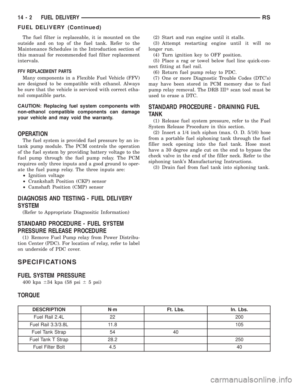
400 kpa634 kpa (58 psi65 psi)
TORQUE
DESCRIPTION N´m Ft. Lbs. In. Lbs.
Fuel Rail 2.4L 22 200
Fuel Rail 3.3/3.8L 11.8 105
Fuel Tank Strap 54 40
Fuel Tank T Strap 28.2 250
Fuel Filter Bolt 4.5 40
14 - 2 FUEL DELIVERYRS
FUEL DELIVERY (Continued)
Page 2913 of 4284
Refer to the maintenance schedules for the recom-
mended fuel filter replacement intervals.
For draining of water from canister, refer to Fuel
Filter/Water Separator Removal/Installation section.
A Water-In-Fuel (WIF) sensor is part of the fuel fil-
ter cap. Refer to Water-In-Fuel Sensor Description/
Operation.
The fuel heater is installed into the filter/separator
housing above the fuel filter. Refer to Fuel Heater
Description/Operation.
FUEL LINES
DESCRIPTION
All fuel lines up to the fuel injection pump are con-
sidered low-pressure. This includes the fuel lines
from: the fuel tank to the fuel transfer pump, and
the fuel transfer pump to the fuel injection pump.
The fuel return lines and the fuel drain lines are also
considered low-pressure lines. High-pressure lines
are used between the fuel injection pump and the
fuel injectors. Also refer to High-Pressure Fuel Lines
Description/Operation.
DESCRIPTIONÐHIGH PRESSURE FUEL LINES
The high-pressure fuel lines are the 4 lines located
between the fuel injection pump and the fuel injec-
torsctor tubes. All other fuel lines are considered low-
pressure lines.
OPERATIONÐHIGH PRESSURE FUEL LINES
CAUTION: The high-pressure fuel lines cannot con-
tact each other or other components. Do not
attempt to weld high-pressure fuel lines or to repair
lines that are damaged. If lines are ever kinked or
bent, they must be replaced. Use only the recom-
mended lines when replacement of high-pressure
fuel line is necessary.
High-pressure fuel lines deliver fuel under
extremely high pressure from the injection pump to
the fuel injectors. The lines expand and contract from
the high-pressure fuel pulses generated during the
injection process. All high-pressure fuel lines are of
the same length and inside diameter. Correct high-
pressure fuel line usage and installation is critical to
smooth engine operation.
WARNING: USE EXTREME CAUTION WHEN
INSPECTING FOR HIGH-PRESSURE FUEL LEAKS.
INSPECT FOR HIGH-PRESSURE FUEL LEAKS WITH
A SHEET OF CARDBOARD. HIGH FUEL INJECTION
PRESSURE CAN CAUSE PERSONAL INJURY IF
CONTACT IS MADE WITH THE SKIN.
DIAGNOSIS AND TESTING - HIGH-PRESSURE
FUEL LINE LEAKS
High-pressure fuel line leaks can cause starting
problems and poor engine performance.
WARNING: DUE TO EXTREME FUEL PRESSURES,
USE EXTREME CAUTION WHEN INSPECTING FOR
HIGH-PRESSURE FUEL LEAKS. DO NOT GET YOUR
HAND NEAR A SUSPECTED LEAK. INSPECT FOR
HIGH-PRESSURE FUEL LEAKS WITH A SHEET OF
CARDBOARD. HIGH FUEL INJECTION PRESSURE
CAN CAUSE PERSONAL INJURY IF CONTACT IS
MADE WITH THE SKIN.
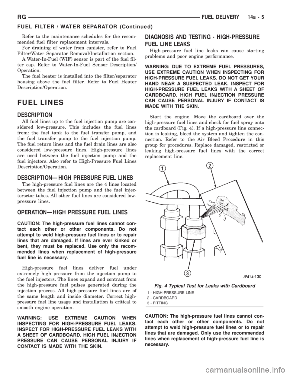
Start the engine. Move the cardboard over the
high-pressure fuel lines and check for fuel spray onto
the cardboard (Fig. 4). If a high-pressure line connec-
tion is leaking, bleed the system and tighten the con-
nection. Refer to the Air Bleed Procedure in this
group for procedures. Replace damaged, restricted or
leaking high-pressure fuel lines with the correct
replacement line.
CAUTION: The high-pressure fuel lines cannot con-
tact each other or other components. Do not
attempt to weld high-pressure fuel lines or to repair
lines that are damaged. Only use the recommended
lines when replacement of high-pressure fuel line is
necessary.
Fig. 4 Typical Test for Leaks with Cardboard
1 - HIGH-PRESSURE LINE
2 - CARDBOARD
3 - FITTING
RGFUEL DELIVERY14a-5
FUEL FILTER / WATER SEPARATOR (Continued)
Page 2968 of 4284
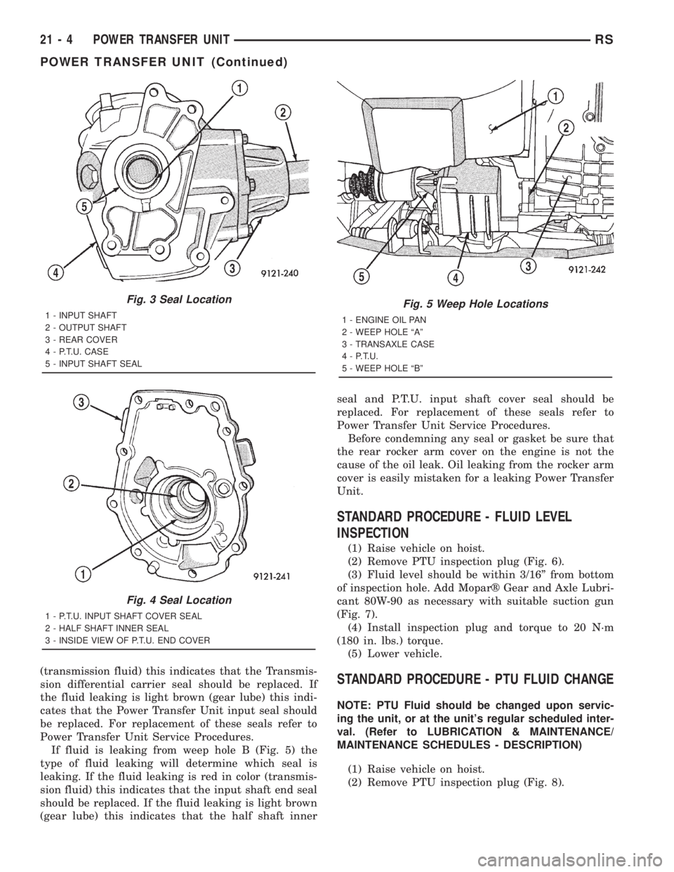
(transmission fluid) this indicates that the Transmis-
sion differential carrier seal should be replaced. If
the fluid leaking is light brown (gear lube) this indi-
cates that the Power Transfer Unit input seal should
be replaced. For replacement of these seals refer to
Power Transfer Unit Service Procedures.
If fluid is leaking from weep hole B (Fig. 5) the
type of fluid leaking will determine which seal is
leaking. If the fluid leaking is red in color (transmis-
sion fluid) this indicates that the input shaft end seal
should be replaced. If the fluid leaking is light brown
(gear lube) this indicates that the half shaft innerseal and P.T.U. input shaft cover seal should be
replaced. For replacement of these seals refer to
Power Transfer Unit Service Procedures.
Before condemning any seal or gasket be sure that
the rear rocker arm cover on the engine is not the
cause of the oil leak. Oil leaking from the rocker arm
cover is easily mistaken for a leaking Power Transfer
Unit.
STANDARD PROCEDURE - FLUID LEVEL
INSPECTION
(1) Raise vehicle on hoist.
(2) Remove PTU inspection plug (Fig. 6).
(3) Fluid level should be within 3/16º from bottom
of inspection hole. Add Moparž Gear and Axle Lubri-
cant 80W-90 as necessary with suitable suction gun
(Fig. 7).
(4) Install inspection plug and torque to 20 N´m
(180 in. lbs.) torque.
(5) Lower vehicle.
STANDARD PROCEDURE - PTU FLUID CHANGE
NOTE: PTU Fluid should be changed upon servic-
ing the unit, or at the unit's regular scheduled inter-
val. (Refer to LUBRICATION & MAINTENANCE/
MAINTENANCE SCHEDULES - DESCRIPTION)
(1) Raise vehicle on hoist.
(2) Remove PTU inspection plug (Fig. 8).
Fig. 3 Seal Location
1 - INPUT SHAFT
2 - OUTPUT SHAFT
3 - REAR COVER
4 - P.T.U. CASE
5 - INPUT SHAFT SEAL
Fig. 4 Seal Location
1 - P.T.U. INPUT SHAFT COVER SEAL
2 - HALF SHAFT INNER SEAL
3 - INSIDE VIEW OF P.T.U. END COVER
Fig. 5 Weep Hole Locations
1 - ENGINE OIL PAN
2 - WEEP HOLE ªAº
3 - TRANSAXLE CASE
4 - P.T.U.
5 - WEEP HOLE ªBº
21 - 4 POWER TRANSFER UNITRS
POWER TRANSFER UNIT (Continued)
Page 3062 of 4284
FLUID
STANDARD PROCEDURE - FLUID LEVEL AND
CONDITION CHECK
NOTE: The transmission and differential sump have
a common oil sump with a communicating opening
between the two.
FLUID LEVEL CHECK
The torque converter fills in both the P Park and N
Neutral positions. Place the selector lever in P Park
to be sure that the fluid level check is accurate.The
engine should be running at idle speed for at
least one minute, with the vehicle on level
ground. This will assure complete oil level sta-
bilization between differential and transmis-
sion.The fluid should be at normal operating
temperature (approximately 82 C. or 180 F.). The
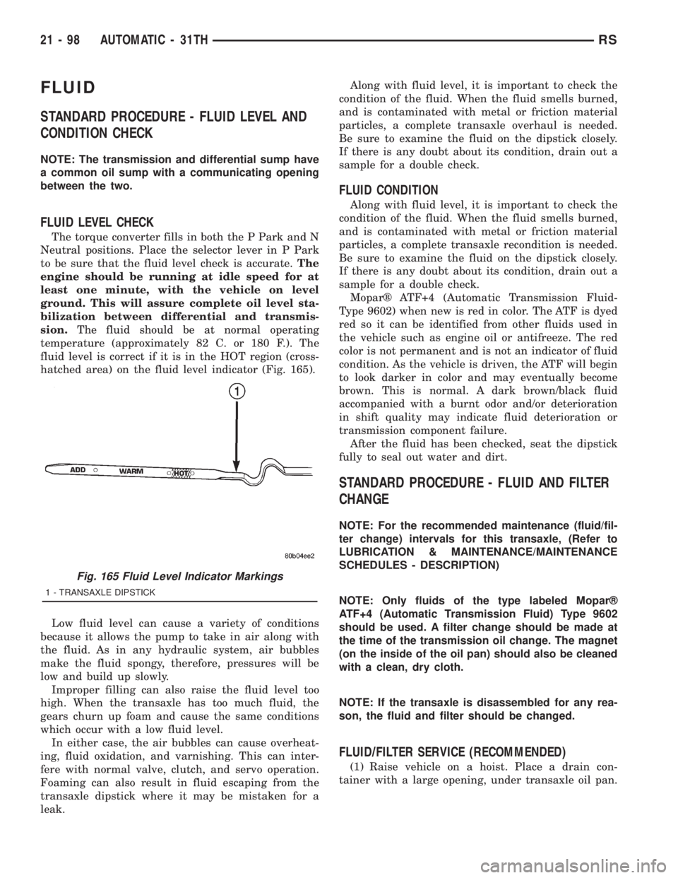
fluid level is correct if it is in the HOT region (cross-
hatched area) on the fluid level indicator (Fig. 165).
Low fluid level can cause a variety of conditions
because it allows the pump to take in air along with
the fluid. As in any hydraulic system, air bubbles
make the fluid spongy, therefore, pressures will be
low and build up slowly.
Improper filling can also raise the fluid level too
high. When the transaxle has too much fluid, the
gears churn up foam and cause the same conditions
which occur with a low fluid level.
In either case, the air bubbles can cause overheat-
ing, fluid oxidation, and varnishing. This can inter-
fere with normal valve, clutch, and servo operation.
Foaming can also result in fluid escaping from the
transaxle dipstick where it may be mistaken for a
leak.Along with fluid level, it is important to check the
condition of the fluid. When the fluid smells burned,
and is contaminated with metal or friction material
particles, a complete transaxle overhaul is needed.
Be sure to examine the fluid on the dipstick closely.
If there is any doubt about its condition, drain out a
sample for a double check.
FLUID CONDITION
Along with fluid level, it is important to check the
condition of the fluid. When the fluid smells burned,
and is contaminated with metal or friction material
particles, a complete transaxle recondition is needed.
Be sure to examine the fluid on the dipstick closely.
If there is any doubt about its condition, drain out a
sample for a double check.
Moparž ATF+4 (Automatic Transmission Fluid-
Type 9602) when new is red in color. The ATF is dyed
red so it can be identified from other fluids used in
the vehicle such as engine oil or antifreeze. The red
color is not permanent and is not an indicator of fluid
condition. As the vehicle is driven, the ATF will begin
to look darker in color and may eventually become
brown. This is normal. A dark brown/black fluid
accompanied with a burnt odor and/or deterioration
in shift quality may indicate fluid deterioration or
transmission component failure.
After the fluid has been checked, seat the dipstick
fully to seal out water and dirt.
STANDARD PROCEDURE - FLUID AND FILTER
CHANGE
NOTE: For the recommended maintenance (fluid/fil-
ter change) intervals for this transaxle, (Refer to
LUBRICATION & MAINTENANCE/MAINTENANCE
SCHEDULES - DESCRIPTION)
NOTE: Only fluids of the type labeled Moparž
ATF+4 (Automatic Transmission Fluid) Type 9602
should be used. A filter change should be made at
the time of the transmission oil change. The magnet
(on the inside of the oil pan) should also be cleaned
with a clean, dry cloth.
NOTE: If the transaxle is disassembled for any rea-
son, the fluid and filter should be changed.
FLUID/FILTER SERVICE (RECOMMENDED)
(1) Raise vehicle on a hoist. Place a drain con-
tainer with a large opening, under transaxle oil pan.
Fig. 165 Fluid Level Indicator Markings
1 - TRANSAXLE DIPSTICK
21 - 98 AUTOMATIC - 31THRS
Page 3210 of 4284
FLUID
STANDARD PROCEDURE - FLUID LEVEL AND
CONDITION CHECK
NOTE: Only transmission fluid of the type labeled
Mopar ATF+4 (Automatic Transmission Fluid±Type
9602) should be used in this transaxle.
FLUID LEVEL CHECK
The transmission sump has a fluid level indicator
(dipstick) to check oil similar to most automatic
transmissions. It is located on the left side of the
engine. Be sure to wipe all dirt from dipstick handle
before removing.
The torque converter fills in both the P Park and N
Neutral positions. Place the selector lever in P Park
to be sure that the fluid level check is accurate.The
engine should be running at idle speed for at
least one minute, with the vehicle on level
ground.At normal operating temperature (approxi-
mately 82 C. or 180 F.), the fluid level is correct if it
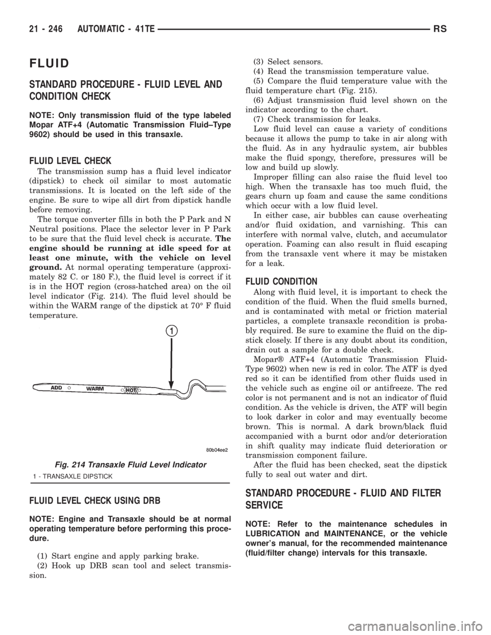
is in the HOT region (cross-hatched area) on the oil
level indicator (Fig. 214). The fluid level should be
within the WARM range of the dipstick at 70É F fluid
temperature.
FLUID LEVEL CHECK USING DRB
NOTE: Engine and Transaxle should be at normal
operating temperature before performing this proce-
dure.
(1) Start engine and apply parking brake.
(2) Hook up DRB scan tool and select transmis-
sion.(3) Select sensors.
(4) Read the transmission temperature value.
(5) Compare the fluid temperature value with the
fluid temperature chart (Fig. 215).
(6) Adjust transmission fluid level shown on the
indicator according to the chart.
(7) Check transmission for leaks.
Low fluid level can cause a variety of conditions
because it allows the pump to take in air along with
the fluid. As in any hydraulic system, air bubbles
make the fluid spongy, therefore, pressures will be
low and build up slowly.
Improper filling can also raise the fluid level too
high. When the transaxle has too much fluid, the
gears churn up foam and cause the same conditions
which occur with a low fluid level.
In either case, air bubbles can cause overheating
and/or fluid oxidation, and varnishing. This can
interfere with normal valve, clutch, and accumulator
operation. Foaming can also result in fluid escaping
from the transaxle vent where it may be mistaken
for a leak.
FLUID CONDITION
Along with fluid level, it is important to check the
condition of the fluid. When the fluid smells burned,
and is contaminated with metal or friction material
particles, a complete transaxle recondition is proba-
bly required. Be sure to examine the fluid on the dip-
stick closely. If there is any doubt about its condition,
drain out a sample for a double check.
Moparž ATF+4 (Automatic Transmission Fluid-
Type 9602) when new is red in color. The ATF is dyed
red so it can be identified from other fluids used in
the vehicle such as engine oil or antifreeze. The red
color is not permanent and is not an indicator of fluid
condition. As the vehicle is driven, the ATF will begin
to look darker in color and may eventually become
brown. This is normal. A dark brown/black fluid
accompanied with a burnt odor and/or deterioration
in shift quality may indicate fluid deterioration or
transmission component failure.
After the fluid has been checked, seat the dipstick
fully to seal out water and dirt.
STANDARD PROCEDURE - FLUID AND FILTER
SERVICE
NOTE: Refer to the maintenance schedules in
LUBRICATION and MAINTENANCE, or the vehicle
owner's manual, for the recommended maintenance
(fluid/filter change) intervals for this transaxle.
Fig. 214 Transaxle Fluid Level Indicator
1 - TRANSAXLE DIPSTICK
21 - 246 AUTOMATIC - 41TERS
Page 3318 of 4284
ADJUSTMENT - DIFFERENTIAL SIDE GEAR
END PLAY
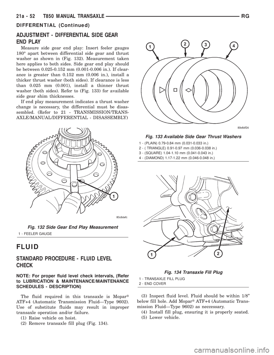
Measure side gear end play: Insert feeler gauges
180É apart between differential side gear and thrust
washer as shown in (Fig. 132). Measurement taken
here applies to both sides. Side gear end play should
be between 0.025-0.152 mm (0.001-0.006 in.). If clear-
ance is greater than 0.152 mm (0.006 in.), install a
thicker thrust washer (both sides). If clearance is less
than 0.025 mm (0.001), install a thinner thrust
washer (both sides). Refer to (Fig. 133) for available
side gear shim thicknesses.
If end play measurement indicates a thrust washer
change is necessary, the differential must be disas-
sembled. (Refer to 21 - TRANSMISSION/TRANS-
AXLE/MANUAL/DIFFERENTIAL - DISASSEMBLY)
FLUID
STANDARD PROCEDURE - FLUID LEVEL
CHECK
NOTE: For proper fluid level check intervals, (Refer
to LUBRICATION & MAINTENANCE/MAINTENANCE
SCHEDULES - DESCRIPTION)
The fluid required in this transaxle is Mopart
ATF+4 (Automatic Transmission FluidÐType 9602).
Use of substitute fluids may result in improper
transaxle operation and/or failure.
(1) Raise vehicle on hoist.
(2) Remove transaxle fill plug (Fig. 134).(3) Inspect fluid level. Fluid should be within 1/8º
below fill hole. Add MopartATF+4 (Automatic Trans-
mission FluidÐType 9602) as neccessary.
(4) Install fill plug, ensuring it is properly seated.
(5) Lower vehicle.
Fig. 132 Side Gear End Play Measurement
1 - FEELER GAUGE
Fig. 133 Available Side Gear Thrust Washers
1 - (PLAIN) 0.79-0.84 mm (0.031-0.033 in.)
2 - ( TRIANGLE) 0.91-0.97 mm (0.036-0.038 in.)
3 - (SQUARE) 1.04-1.10 mm (0.041-0.043 in.)
4 - (DIAMOND) 1.17-1.22 mm (0.046-0.048 in.)
Fig. 134 Transaxle Fill Plug
1 - TRANSAXLE FILL PLUG
2 - END COVER
21a - 52 T850 MANUAL TRANSAXLERG
DIFFERENTIAL (Continued)
Page 3319 of 4284
STANDARD PROCEDURE - FLUID DRAIN AND
FILL
NOTE: For proper fluid change intervals, (Refer to
LUBRICATION & MAINTENANCE/MAINTENANCE
SCHEDULES - DESCRIPTION)
The fluid required in this transaxle is Mopart
ATF+4 (Automatic Transmission FluidÐType 9602).
Use of substitute fluids may result in improper
transaxle operation and/or failure.
FLUID DRAIN
(1) Raise vehicle on hoist.
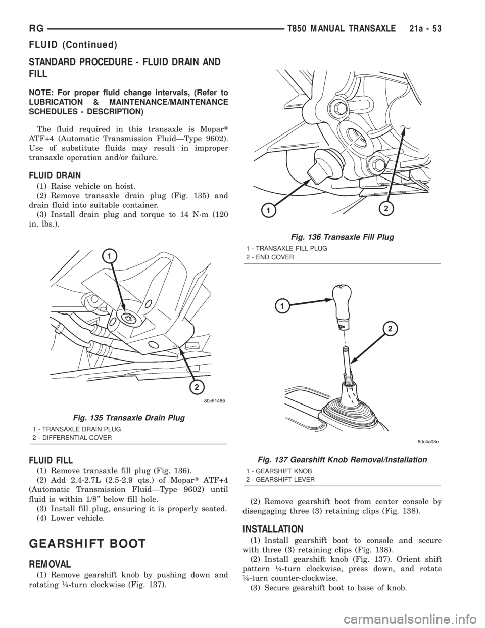
(2) Remove transaxle drain plug (Fig. 135) and
drain fluid into suitable container.
(3) Install drain plug and torque to 14 N´m (120
in. lbs.).
FLUID FILL
(1) Remove transaxle fill plug (Fig. 136).
(2) Add 2.4-2.7L (2.5-2.9 qts.) of MopartATF+4
(Automatic Transmission FluidÐType 9602) until
fluid is within 1/8º below fill hole.
(3) Install fill plug, ensuring it is properly seated.
(4) Lower vehicle.
GEARSHIFT BOOT
REMOVAL
(1) Remove gearshift knob by pushing down and
rotating ò-turn clockwise (Fig. 137).(2) Remove gearshift boot from center console by
disengaging three (3) retaining clips (Fig. 138).
INSTALLATION
(1) Install gearshift boot to console and secure
with three (3) retaining clips (Fig. 138).
(2) Install gearshift knob (Fig. 137). Orient shift
pattern ò-turn clockwise, press down, and rotate
ò-turn counter-clockwise.
(3) Secure gearshift boot to base of knob.
Fig. 135 Transaxle Drain Plug
1 - TRANSAXLE DRAIN PLUG
2 - DIFFERENTIAL COVER
Fig. 136 Transaxle Fill Plug
1 - TRANSAXLE FILL PLUG
2 - END COVER
Fig. 137 Gearshift Knob Removal/Installation
1 - GEARSHIFT KNOB
2 - GEARSHIFT LEVER
RGT850 MANUAL TRANSAXLE21a-53
FLUID (Continued)