2001 CHRYSLER VOYAGER torque
[x] Cancel search: torquePage 3044 of 4284
(5) Back off front band adjusting screw 2ò turns.
(6) Hold adjuster screw in position and tighten
locknut to 47 N´m (35 ft. lbs.) torque.
(7) Install air cleaner assembly.
(8) Connect battery negative cable.
ADJUSTMENTS - REAR BAND
The transmission oil pan must be removed for
access to the rear (low/reverse) band adjusting screw.
(1) Raise vehicle.
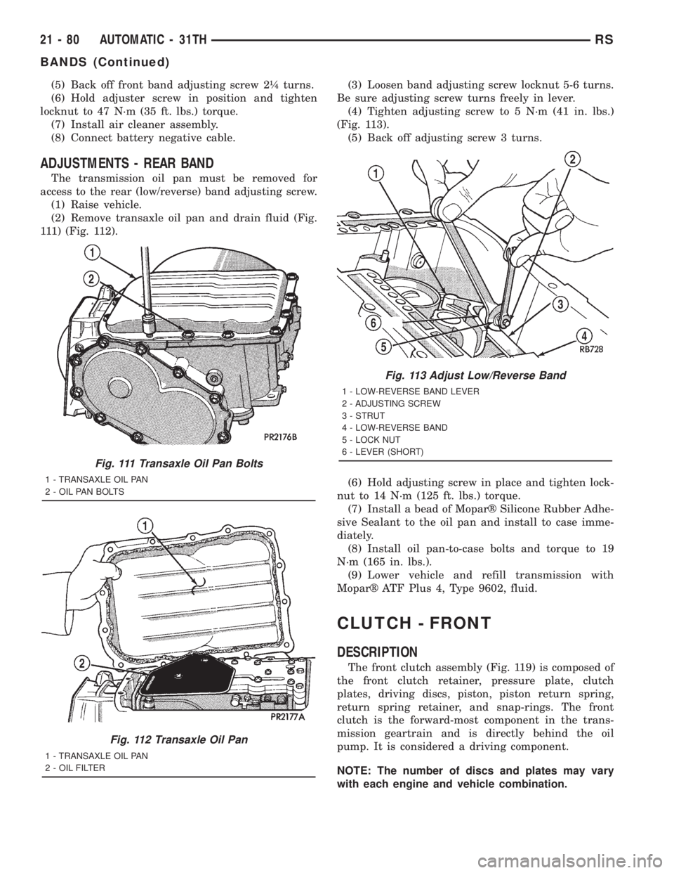
(2) Remove transaxle oil pan and drain fluid (Fig.
111) (Fig. 112).(3) Loosen band adjusting screw locknut 5-6 turns.
Be sure adjusting screw turns freely in lever.
(4) Tighten adjusting screw to 5 N´m (41 in. lbs.)
(Fig. 113).
(5) Back off adjusting screw 3 turns.
(6) Hold adjusting screw in place and tighten lock-
nut to 14 N´m (125 ft. lbs.) torque.
(7) Install a bead of Moparž Silicone Rubber Adhe-
sive Sealant to the oil pan and install to case imme-
diately.
(8) Install oil pan-to-case bolts and torque to 19
N´m (165 in. lbs.).
(9) Lower vehicle and refill transmission with
Moparž ATF Plus 4, Type 9602, fluid.
CLUTCH - FRONT
DESCRIPTION
The front clutch assembly (Fig. 119) is composed of
the front clutch retainer, pressure plate, clutch
plates, driving discs, piston, piston return spring,
return spring retainer, and snap-rings. The front
clutch is the forward-most component in the trans-
mission geartrain and is directly behind the oil
pump. It is considered a driving component.
NOTE: The number of discs and plates may vary
with each engine and vehicle combination.
Fig. 111 Transaxle Oil Pan Bolts
1 - TRANSAXLE OIL PAN
2 - OIL PAN BOLTS
Fig. 112 Transaxle Oil Pan
1 - TRANSAXLE OIL PAN
2 - OIL FILTER
Fig. 113 Adjust Low/Reverse Band
1 - LOW-REVERSE BAND LEVER
2 - ADJUSTING SCREW
3 - STRUT
4 - LOW-REVERSE BAND
5 - LOCK NUT
6 - LEVER (SHORT)
21 - 80 AUTOMATIC - 31THRS
BANDS (Continued)
Page 3045 of 4284
OPERATION
To apply the clutch, pressure is applied between
the clutch retainer and piston. The fluid pressure is
provided by the oil pump, transferred through the
control valves and passageways, and enters the
clutch through the hub of the reaction shaft support.
With pressure applied between the clutch retainer
and piston, the piston moves away from the clutch
retainer and compresses the clutch pack. This action
applies the clutch pack, allowing torque to flow
through the input shaft into the driving discs, and
into the clutch plates and pressure plate that are
lugged to the clutch retainer. The waved snap-ring is
used to cushion the application of the clutch pack. In
some transmissions, the snap-ring is selective and
used to adjust clutch pack clearance.
When pressure is released from the piston, the
spring returns the piston to its fully released position
and disengages the clutch. The release spring also
helps to cushion the application of the clutch assem-
bly. When the clutch is in the process of being
released by the release spring, fluid flows through a
vent and one-way ball-check-valve located in the
clutch retainer. The check-valve is needed to elimi-
nate the possibility of plate drag caused by centrifu-
gal force acting on the residual fluid trapped in the
clutch piston retainer.
DISASSEMBLY
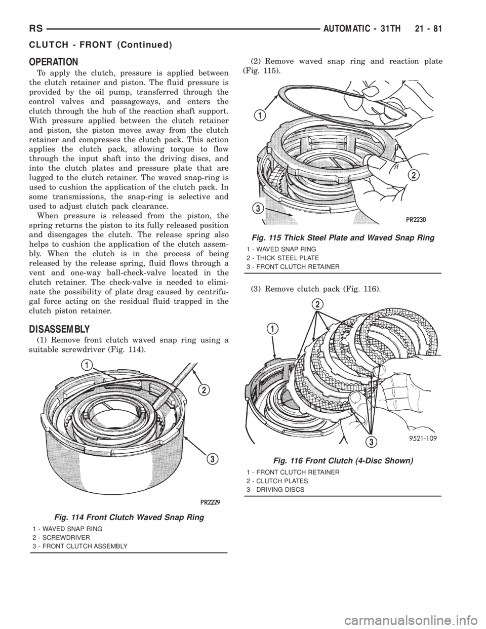
(1) Remove front clutch waved snap ring using a
suitable screwdriver (Fig. 114).(2) Remove waved snap ring and reaction plate
(Fig. 115).
(3) Remove clutch pack (Fig. 116).
Fig. 114 Front Clutch Waved Snap Ring
1 - WAVED SNAP RING
2 - SCREWDRIVER
3 - FRONT CLUTCH ASSEMBLY
Fig. 115 Thick Steel Plate and Waved Snap Ring
1 - WAVED SNAP RING
2 - THICK STEEL PLATE
3 - FRONT CLUTCH RETAINER
Fig. 116 Front Clutch (4-Disc Shown)
1 - FRONT CLUTCH RETAINER
2 - CLUTCH PLATES
3 - DRIVING DISCS
RSAUTOMATIC - 31TH21-81
CLUTCH - FRONT (Continued)
Page 3049 of 4284
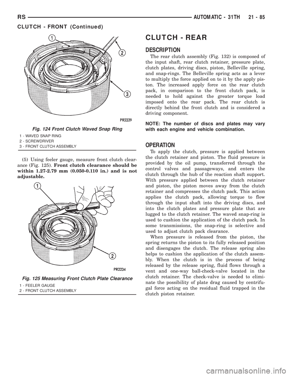
(5) Using feeler gauge, measure front clutch clear-
ance (Fig. 125).Front clutch clearance should be
within 1.27-2.79 mm (0.050-0.110 in.) and is not
adjustable.
CLUTCH - REAR
DESCRIPTION
The rear clutch assembly (Fig. 132) is composed of
the input shaft, rear clutch retainer, pressure plate,
clutch plates, driving discs, piston, Belleville spring,
and snap-rings. The Belleville spring acts as a lever
to multiply the force applied on to it by the apply pis-
ton. The increased apply force on the rear clutch
pack, in comparison to the front clutch pack, is
needed to hold against the greater torque load
imposed onto the rear pack. The rear clutch is
directly behind the front clutch and is considered a
driving component.
NOTE: The number of discs and plates may vary
with each engine and vehicle combination.
OPERATION
To apply the clutch, pressure is applied between
the clutch retainer and piston. The fluid pressure is
provided by the oil pump, transferred through the
control valves and passageways, and enters the
clutch through the hub of the reaction shaft support.
With pressure applied between the clutch retainer
and piston, the piston moves away from the clutch
retainer and compresses the clutch pack. This action
applies the clutch pack, allowing torque to flow
through the input shaft into the driving discs, and
into the clutch plates and pressure plate that are
lugged to the clutch retainer. The waved snap-ring is
used to cushion the application of the clutch pack. In
some transmissions, the snap-ring is selective and
used to adjust clutch pack clearance.
When pressure is released from the piston, the
spring returns the piston to its fully released position
and disengages the clutch. The release spring also
helps to cushion the application of the clutch assem-
bly. When the clutch is in the process of being
released by the release spring, fluid flows through a
vent and one-way ball-check-valve located in the
clutch retainer. The check-valve is needed to elimi-
nate the possibility of plate drag caused by centrifu-
gal force acting on the residual fluid trapped in the
clutch piston retainer.
Fig. 124 Front Clutch Waved Snap Ring
1 - WAVED SNAP RING
2 - SCREWDRIVER
3 - FRONT CLUTCH ASSEMBLY
Fig. 125 Measuring Front Clutch Plate Clearance
1 - FEELER GAUGE
2 - FRONT CLUTCH ASSEMBLY
RSAUTOMATIC - 31TH21-85
CLUTCH - FRONT (Continued)
Page 3054 of 4284
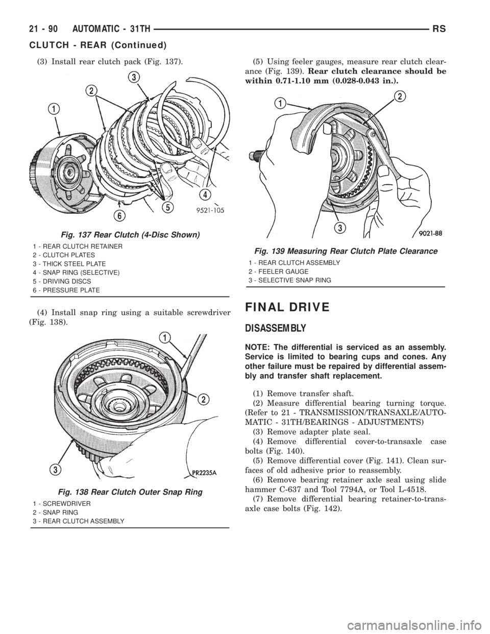
(3) Install rear clutch pack (Fig. 137).
(4) Install snap ring using a suitable screwdriver
(Fig. 138).(5) Using feeler gauges, measure rear clutch clear-
ance (Fig. 139).Rear clutch clearance should be
within 0.71-1.10 mm (0.028-0.043 in.).
FINAL DRIVE
DISASSEMBLY
NOTE: The differential is serviced as an assembly.
Service is limited to bearing cups and cones. Any
other failure must be repaired by differential assem-
bly and transfer shaft replacement.
(1) Remove transfer shaft.
(2) Measure differential bearing turning torque.
(Refer to 21 - TRANSMISSION/TRANSAXLE/AUTO-
MATIC - 31TH/BEARINGS - ADJUSTMENTS)
(3) Remove adapter plate seal.
(4) Remove differential cover-to-transaxle case
bolts (Fig. 140).
(5) Remove differential cover (Fig. 141). Clean sur-
faces of old adhesive prior to reassembly.
(6) Remove bearing retainer axle seal using slide
hammer C-637 and Tool 7794A, or Tool L-4518.
(7) Remove differential bearing retainer-to-trans-
axle case bolts (Fig. 142).
Fig. 137 Rear Clutch (4-Disc Shown)
1 - REAR CLUTCH RETAINER
2 - CLUTCH PLATES
3 - THICK STEEL PLATE
4 - SNAP RING (SELECTIVE)
5 - DRIVING DISCS
6 - PRESSURE PLATE
Fig. 138 Rear Clutch Outer Snap Ring
1 - SCREWDRIVER
2 - SNAP RING
3 - REAR CLUTCH ASSEMBLY
Fig. 139 Measuring Rear Clutch Plate Clearance
1 - REAR CLUTCH ASSEMBLY
2 - FEELER GAUGE
3 - SELECTIVE SNAP RING
21 - 90 AUTOMATIC - 31THRS
CLUTCH - REAR (Continued)
Page 3058 of 4284
ASSEMBLY
NOTE: The differential is serviced as an assembly.
Service is limited to bearing cups and cones. Any
other failure must be repaired by differential assem-
bly and transfer shaft replacement.
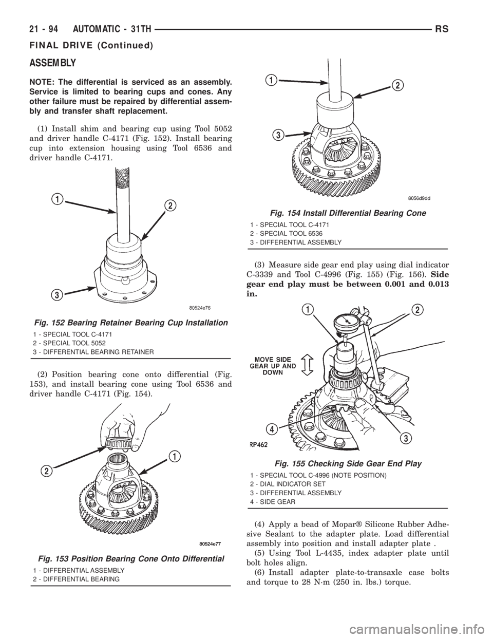
(1) Install shim and bearing cup using Tool 5052
and driver handle C-4171 (Fig. 152). Install bearing
cup into extension housing using Tool 6536 and
driver handle C-4171.
(2) Position bearing cone onto differential (Fig.
153), and install bearing cone using Tool 6536 and
driver handle C-4171 (Fig. 154).(3) Measure side gear end play using dial indicator
C-3339 and Tool C-4996 (Fig. 155) (Fig. 156).Side
gear end play must be between 0.001 and 0.013
in.
(4) Apply a bead of Moparž Silicone Rubber Adhe-
sive Sealant to the adapter plate. Load differential
assembly into position and install adapter plate .
(5) Using Tool L-4435, index adapter plate until
bolt holes align.
(6) Install adapter plate-to-transaxle case bolts
and torque to 28 N´m (250 in. lbs.) torque.
Fig. 152 Bearing Retainer Bearing Cup Installation
1 - SPECIAL TOOL C-4171
2 - SPECIAL TOOL 5052
3 - DIFFERENTIAL BEARING RETAINER
Fig. 153 Position Bearing Cone Onto Differential
1 - DIFFERENTIAL ASSEMBLY
2 - DIFFERENTIAL BEARING
Fig. 154 Install Differential Bearing Cone
1 - SPECIAL TOOL C-4171
2 - SPECIAL TOOL 6536
3 - DIFFERENTIAL ASSEMBLY
Fig. 155 Checking Side Gear End Play
1 - SPECIAL TOOL C-4996 (NOTE POSITION)
2 - DIAL INDICATOR SET
3 - DIFFERENTIAL ASSEMBLY
4 - SIDE GEAR
21 - 94 AUTOMATIC - 31THRS
FINAL DRIVE (Continued)
Page 3059 of 4284
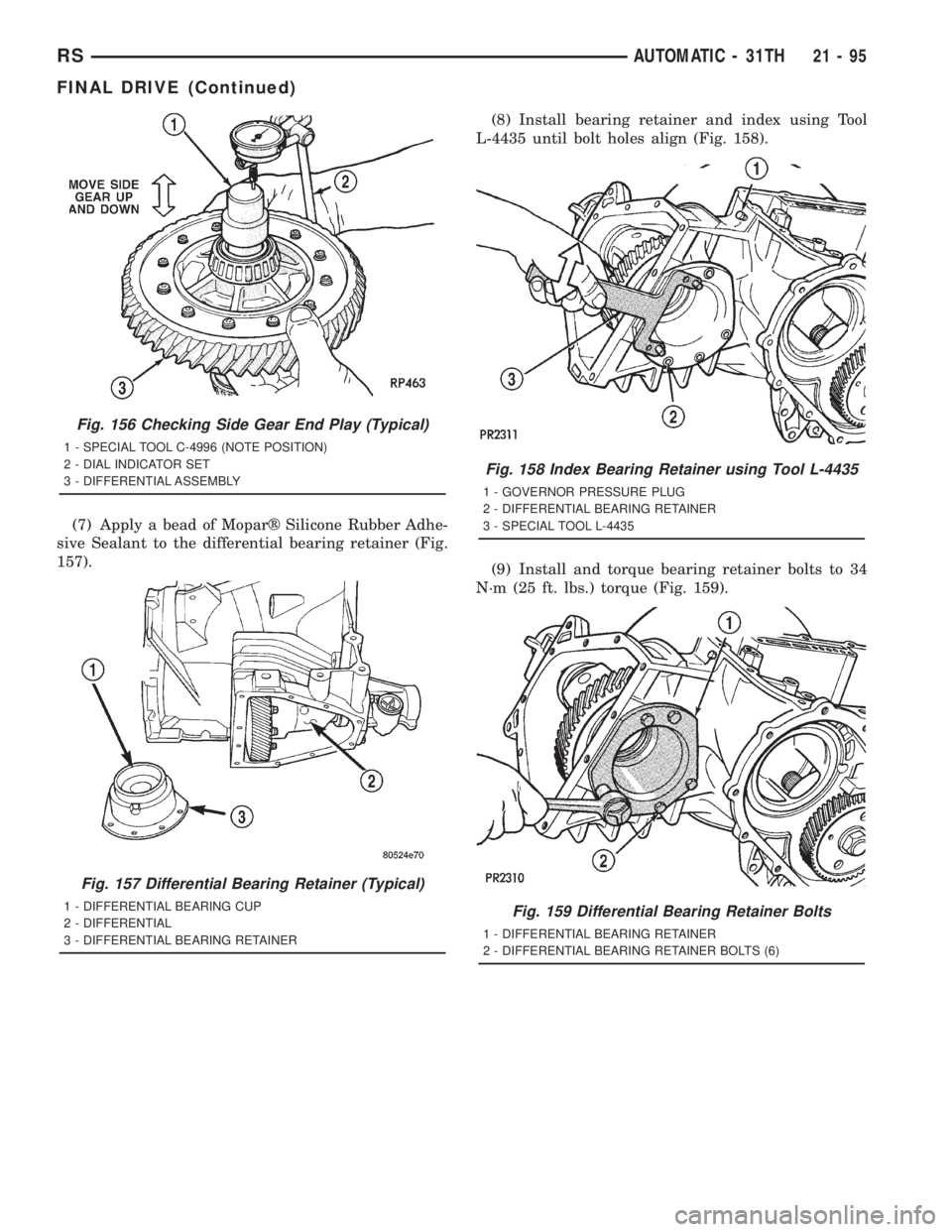
(7) Apply a bead of Moparž Silicone Rubber Adhe-
sive Sealant to the differential bearing retainer (Fig.
157).(8) Install bearing retainer and index using Tool
L-4435 until bolt holes align (Fig. 158).
(9) Install and torque bearing retainer bolts to 34
N´m (25 ft. lbs.) torque (Fig. 159).
Fig. 156 Checking Side Gear End Play (Typical)
1 - SPECIAL TOOL C-4996 (NOTE POSITION)
2 - DIAL INDICATOR SET
3 - DIFFERENTIAL ASSEMBLY
Fig. 157 Differential Bearing Retainer (Typical)
1 - DIFFERENTIAL BEARING CUP
2 - DIFFERENTIAL
3 - DIFFERENTIAL BEARING RETAINER
Fig. 158 Index Bearing Retainer using Tool L-4435
1 - GOVERNOR PRESSURE PLUG
2 - DIFFERENTIAL BEARING RETAINER
3 - SPECIAL TOOL L-4435
Fig. 159 Differential Bearing Retainer Bolts
1 - DIFFERENTIAL BEARING RETAINER
2 - DIFFERENTIAL BEARING RETAINER BOLTS (6)
RSAUTOMATIC - 31TH21-95
FINAL DRIVE (Continued)
Page 3060 of 4284
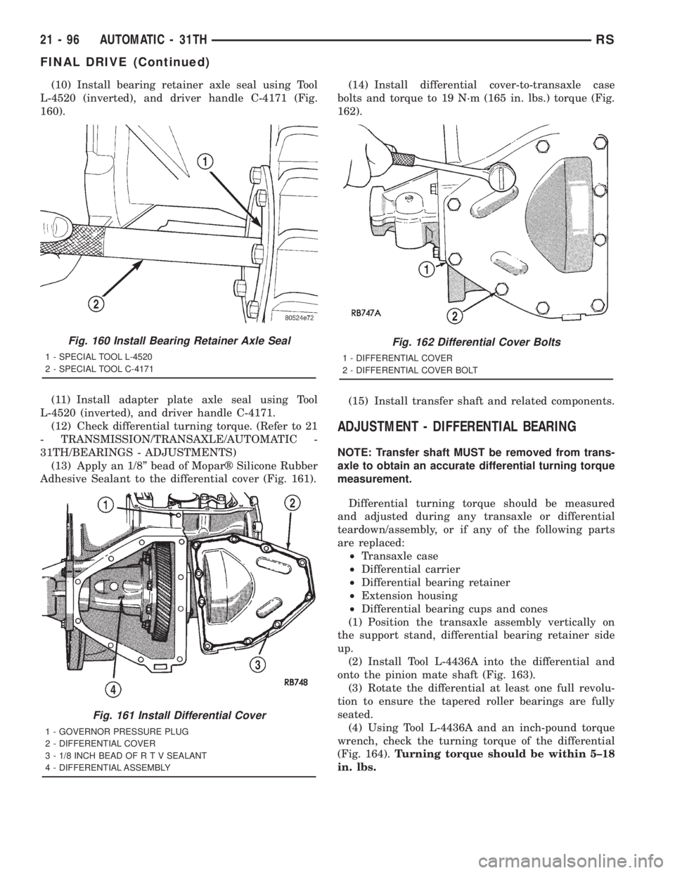
(10) Install bearing retainer axle seal using Tool
L-4520 (inverted), and driver handle C-4171 (Fig.
160).
(11) Install adapter plate axle seal using Tool
L-4520 (inverted), and driver handle C-4171.
(12) Check differential turning torque. (Refer to 21
- TRANSMISSION/TRANSAXLE/AUTOMATIC -
31TH/BEARINGS - ADJUSTMENTS)
(13) Apply an 1/8º bead of Moparž Silicone Rubber
Adhesive Sealant to the differential cover (Fig. 161).(14) Install differential cover-to-transaxle case
bolts and torque to 19 N´m (165 in. lbs.) torque (Fig.
162).
(15) Install transfer shaft and related components.
ADJUSTMENT - DIFFERENTIAL BEARING
NOTE: Transfer shaft MUST be removed from trans-
axle to obtain an accurate differential turning torque
measurement.
Differential turning torque should be measured
and adjusted during any transaxle or differential
teardown/assembly, or if any of the following parts
are replaced:
²Transaxle case
²Differential carrier
²Differential bearing retainer
²Extension housing
²Differential bearing cups and cones
(1) Position the transaxle assembly vertically on
the support stand, differential bearing retainer side
up.
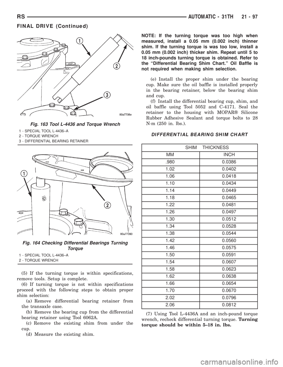
(2) Install Tool L-4436A into the differential and
onto the pinion mate shaft (Fig. 163).
(3) Rotate the differential at least one full revolu-
tion to ensure the tapered roller bearings are fully
seated.
(4) Using Tool L-4436A and an inch-pound torque
wrench, check the turning torque of the differential
(Fig. 164).Turning torque should be within 5±18
in. lbs.
Fig. 160 Install Bearing Retainer Axle Seal
1 - SPECIAL TOOL L-4520
2 - SPECIAL TOOL C-4171
Fig. 161 Install Differential Cover
1 - GOVERNOR PRESSURE PLUG
2 - DIFFERENTIAL COVER
3 - 1/8 INCH BEAD OF R T V SEALANT
4 - DIFFERENTIAL ASSEMBLY
Fig. 162 Differential Cover Bolts
1 - DIFFERENTIAL COVER
2 - DIFFERENTIAL COVER BOLT
21 - 96 AUTOMATIC - 31THRS
FINAL DRIVE (Continued)
Page 3061 of 4284
(5) If the turning torque is within specifications,
remove tools. Setup is complete.
(6) If turning torque is not within specifications
proceed with the following steps to obtain proper
shim selection:
(a) Remove differential bearing retainer from
the transaxle case.
(b) Remove the bearing cup from the differential
bearing retainer using Tool 6062A.
(c) Remove the existing shim from under the
cup.
(d) Measure the existing shim.NOTE: If the turning torque was too high when
measured, install a 0.05 mm (0.002 inch) thinner
shim. If the turning torque is was too low, install a
0.05 mm (0.002 inch) thicker shim. Repeat until 5 to
18 inch-pounds turning torque is obtained. Refer to
the ªDifferential Bearing Shim Chart.º Oil Baffle is
not required when making shim selection.
(e) Install the proper shim under the bearing
cup. Make sure the oil baffle is installed properly
in the bearing retainer, below the bearing shim
and cup.
(f) Install the differential bearing cup, shim, and
oil baffle using Tool 5052 and C-4171. Seal the
retainer to the housing with MOPARž Silicone
Rubber Adhesive Sealant and torque bolts to 28
N´m (250 in. lbs.).
DIFFERENTIAL BEARING SHIM CHART
SHIM THICKNESS
MM INCH
.980 0.0386
1.02 0.0402
1.06 0.0418
1.10 0.0434
1.14 0.0449
1.18 0.0465
1.22 0.0481
1.26 0.0497
1.30 0.0512
1.34 0.0528
1.38 0.0544
1.42 0.0560
1.46 0.0575
1.50 0.0591
1.54 0.0607
1.58 0.0623
1.62 0.0638
1.66 0.0654
1.70 0.0670
2.02 0.0796
2.06 0.0812
(7) Using Tool L-4436A and an inch-pound torque
wrench, recheck differential turning torque.Turning
torque should be within 5±18 in. lbs.
Fig. 163 Tool L-4436 and Torque Wrench
1 - SPECIAL TOOL L-4436±A
2 - TORQUE WRENCH
3 - DIFFERENTIAL BEARING RETAINER
Fig. 164 Checking Differential Bearings Turning
Torque
1 - SPECIAL TOOL L-4436±A
2 - TORQUE WRENCH
RSAUTOMATIC - 31TH21-97
FINAL DRIVE (Continued)