2001 CHRYSLER VOYAGER diagram
[x] Cancel search: diagramPage 4048 of 4284
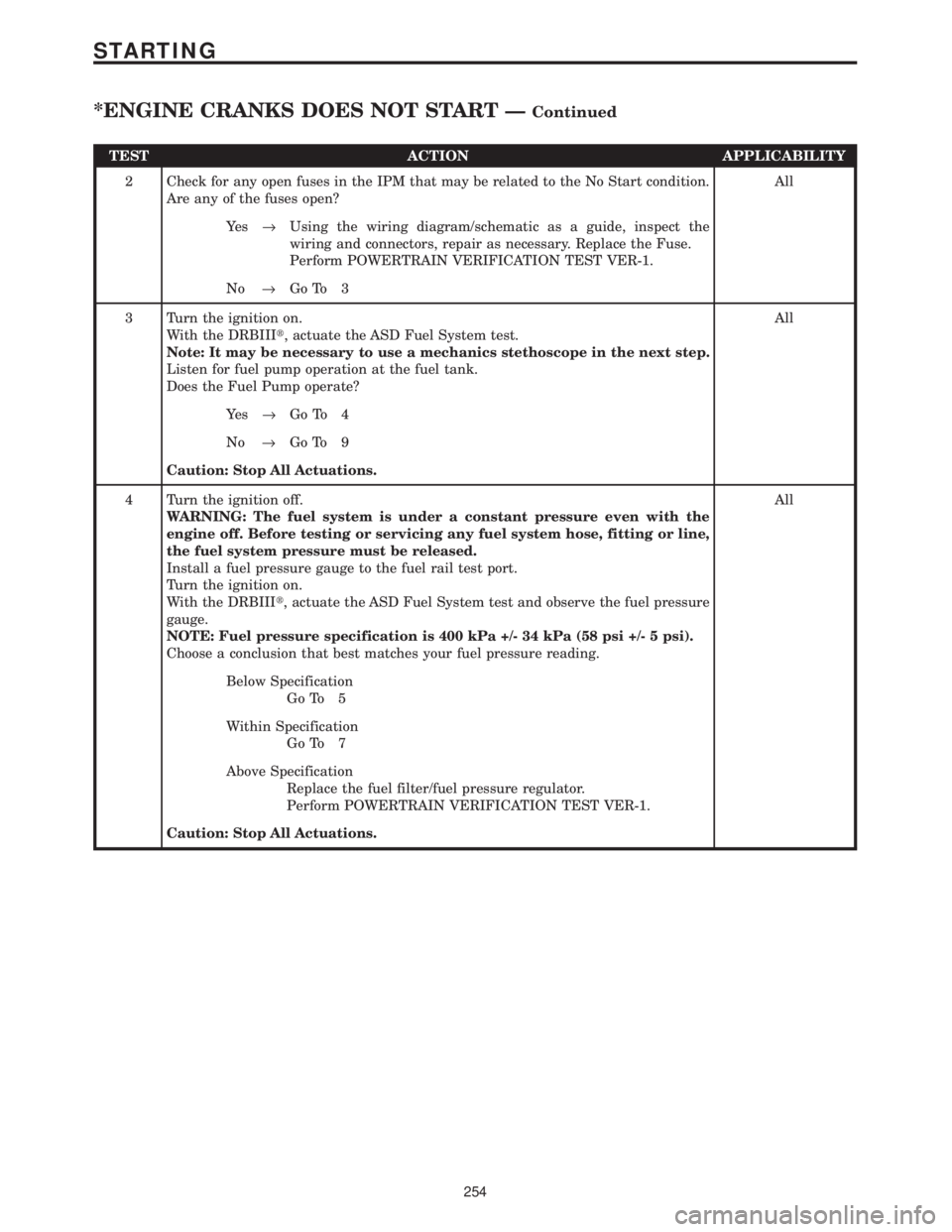
TEST ACTION APPLICABILITY
2 Check for any open fuses in the IPM that may be related to the No Start condition.
Are any of the fuses open?All
Ye s®Using the wiring diagram/schematic as a guide, inspect the
wiring and connectors, repair as necessary. Replace the Fuse.
Perform POWERTRAIN VERIFICATION TEST VER-1.
No®Go To 3
3 Turn the ignition on.
With the DRBIIIt, actuate the ASD Fuel System test.
Note: It may be necessary to use a mechanics stethoscope in the next step.
Listen for fuel pump operation at the fuel tank.
Does the Fuel Pump operate?All
Ye s®Go To 4
No®Go To 9
Caution: Stop All Actuations.
4 Turn the ignition off.
WARNING: The fuel system is under a constant pressure even with the
engine off. Before testing or servicing any fuel system hose, fitting or line,
the fuel system pressure must be released.
Install a fuel pressure gauge to the fuel rail test port.
Turn the ignition on.
With the DRBIIIt, actuate the ASD Fuel System test and observe the fuel pressure
gauge.
NOTE: Fuel pressure specification is 400 kPa +/- 34 kPa (58 psi +/- 5 psi).
Choose a conclusion that best matches your fuel pressure reading.All
Below Specification
Go To 5
Within Specification
Go To 7
Above Specification
Replace the fuel filter/fuel pressure regulator.
Perform POWERTRAIN VERIFICATION TEST VER-1.
Caution: Stop All Actuations.
254
STARTING
*ENGINE CRANKS DOES NOT START ÐContinued
Page 4097 of 4284
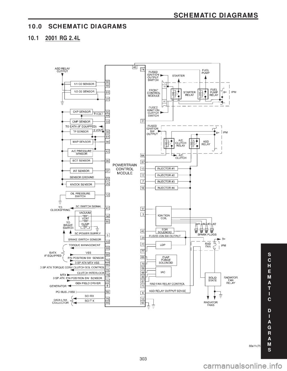
10.0 SCHEMATIC DIAGRAMS
10.1 2001 RG 2.4L
S
C
H
E
M
A
T
I
C
D
I
A
G
R
A
M
S
303
SCHEMATIC DIAGRAMS
Page 4098 of 4284
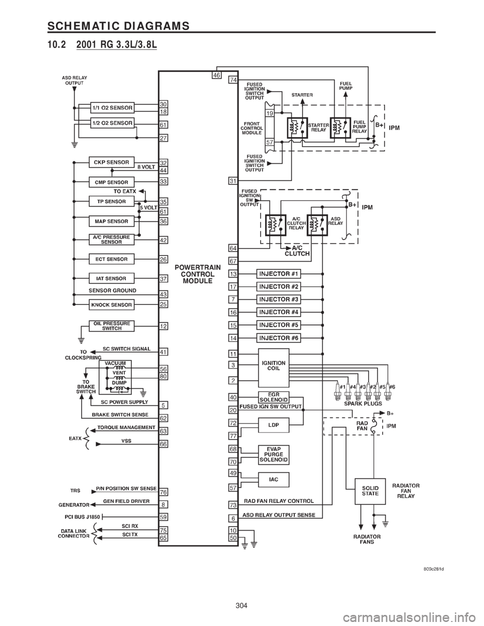
10.2 2001 RG 3.3L/3.8L
304
SCHEMATIC DIAGRAMS
Page 4103 of 4284
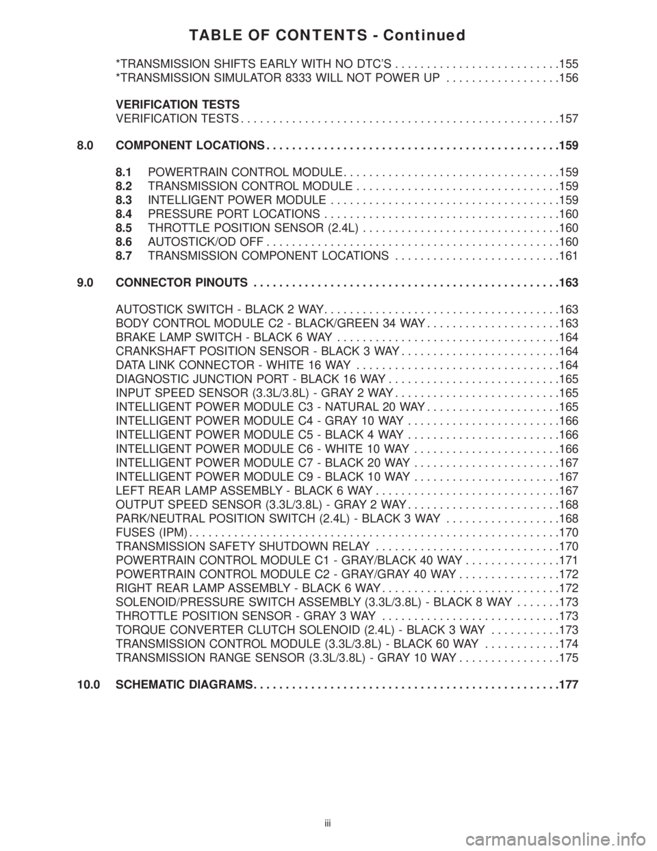
TABLE OF CONTENTS - Continued
*TRANSMISSION SHIFTS EARLY WITH NO DTC'S..........................155
*TRANSMISSION SIMULATOR 8333 WILL NOT POWER UP..................156
VERIFICATION TESTS
VERIFICATION TESTS..................................................157
8.0 COMPONENT LOCATIONS..............................................159
8.1POWERTRAIN CONTROL MODULE..................................159
8.2TRANSMISSION CONTROL MODULE................................159
8.3INTELLIGENT POWER MODULE....................................159
8.4PRESSURE PORT LOCATIONS.....................................160
8.5THROTTLE POSITION SENSOR (2.4L)...............................160
8.6AUTOSTICK/OD OFF..............................................160
8.7TRANSMISSION COMPONENT LOCATIONS..........................161
9.0 CONNECTOR PINOUTS................................................163
AUTOSTICK SWITCH - BLACK 2 WAY.....................................163
BODY CONTROL MODULE C2 - BLACK/GREEN 34 WAY.....................163
BRAKE LAMP SWITCH - BLACK 6 WAY...................................164
CRANKSHAFT POSITION SENSOR - BLACK 3 WAY.........................164
DATA LINK CONNECTOR - WHITE 16 WAY................................164
DIAGNOSTIC JUNCTION PORT - BLACK 16 WAY...........................165
INPUT SPEED SENSOR (3.3L/3.8L) - GRAY 2 WAY..........................165
INTELLIGENT POWER MODULE C3 - NATURAL 20 WAY.....................165
INTELLIGENT POWER MODULE C4 - GRAY 10 WAY........................166
INTELLIGENT POWER MODULE C5 - BLACK 4 WAY........................166
INTELLIGENT POWER MODULE C6 - WHITE 10 WAY.......................166
INTELLIGENT POWER MODULE C7 - BLACK 20 WAY.......................167
INTELLIGENT POWER MODULE C9 - BLACK 10 WAY.......................167
LEFT REAR LAMP ASSEMBLY - BLACK 6 WAY.............................167
OUTPUT SPEED SENSOR (3.3L/3.8L) - GRAY 2 WAY........................168
PARK/NEUTRAL POSITION SWITCH (2.4L) - BLACK 3 WAY..................168
FUSES (IPM)..........................................................170
TRANSMISSION SAFETY SHUTDOWN RELAY.............................170
POWERTRAIN CONTROL MODULE C1 - GRAY/BLACK 40 WAY...............171
POWERTRAIN CONTROL MODULE C2 - GRAY/GRAY 40 WAY................172
RIGHT REAR LAMP ASSEMBLY - BLACK 6 WAY............................172
SOLENOID/PRESSURE SWITCH ASSEMBLY (3.3L/3.8L) - BLACK 8 WAY.......173
THROTTLE POSITION SENSOR - GRAY 3 WAY............................173
TORQUE CONVERTER CLUTCH SOLENOID (2.4L) - BLACK 3 WAY...........173
TRANSMISSION CONTROL MODULE (3.3L/3.8L) - BLACK 60 WAY............174
TRANSMISSION RANGE SENSOR (3.3L/3.8L) - GRAY 10 WAY................175
10.0 SCHEMATIC DIAGRAMS................................................177
iii
Page 4128 of 4284
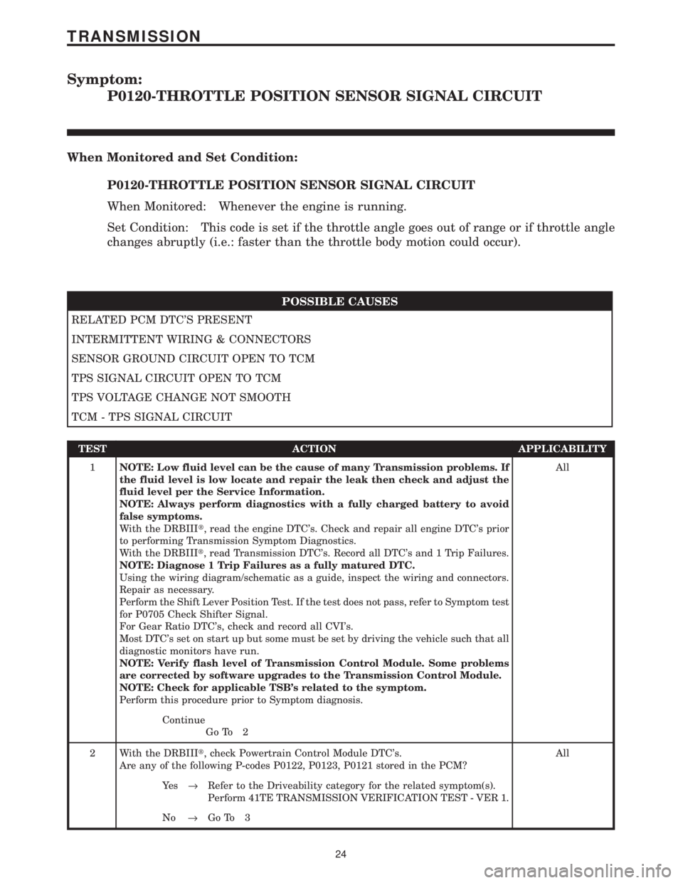
Symptom:
P0120-THROTTLE POSITION SENSOR SIGNAL CIRCUIT
When Monitored and Set Condition:
P0120-THROTTLE POSITION SENSOR SIGNAL CIRCUIT
When Monitored: Whenever the engine is running.
Set Condition: This code is set if the throttle angle goes out of range or if throttle angle
changes abruptly (i.e.: faster than the throttle body motion could occur).
POSSIBLE CAUSES
RELATED PCM DTC'S PRESENT
INTERMITTENT WIRING & CONNECTORS
SENSOR GROUND CIRCUIT OPEN TO TCM
TPS SIGNAL CIRCUIT OPEN TO TCM
TPS VOLTAGE CHANGE NOT SMOOTH
TCM - TPS SIGNAL CIRCUIT
TEST ACTION APPLICABILITY
1NOTE: Low fluid level can be the cause of many Transmission problems. If
the fluid level is low locate and repair the leak then check and adjust the
fluid level per the Service Information.
NOTE: Always perform diagnostics with a fully charged battery to avoid
false symptoms.
With the DRBIIIt, read the engine DTC's. Check and repair all engine DTC's prior
to performing Transmission Symptom Diagnostics.
With the DRBIIIt, read Transmission DTC's. Record all DTC's and 1 Trip Failures.
NOTE: Diagnose 1 Trip Failures as a fully matured DTC.
Using the wiring diagram/schematic as a guide, inspect the wiring and connectors.
Repair as necessary.
Perform the Shift Lever Position Test. If the test does not pass, refer to Symptom test
for P0705 Check Shifter Signal.
For Gear Ratio DTC's, check and record all CVI's.
Most DTC's set on start up but some must be set by driving the vehicle such that all
diagnostic monitors have run.
NOTE: Verify flash level of Transmission Control Module. Some problems
are corrected by software upgrades to the Transmission Control Module.
NOTE: Check for applicable TSB's related to the symptom.
Perform this procedure prior to Symptom diagnosis.All
Continue
Go To 2
2 With the DRBIIIt, check Powertrain Control Module DTC's.
Are any of the following P-codes P0122, P0123, P0121 stored in the PCM?All
Ye s®Refer to the Driveability category for the related symptom(s).
Perform 41TE TRANSMISSION VERIFICATION TEST - VER 1.
No®Go To 3
24
TRANSMISSION
Page 4136 of 4284
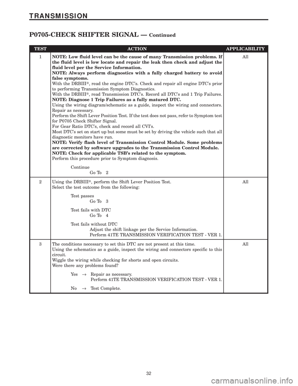
TEST ACTION APPLICABILITY
1NOTE: Low fluid level can be the cause of many Transmission problems. If
the fluid level is low locate and repair the leak then check and adjust the
fluid level per the Service Information.
NOTE: Always perform diagnostics with a fully charged battery to avoid
false symptoms.
With the DRBIIIt, read the engine DTC's. Check and repair all engine DTC's prior
to performing Transmission Symptom Diagnostics.
With the DRBIIIt, read Transmission DTC's. Record all DTC's and 1 Trip Failures.
NOTE: Diagnose 1 Trip Failures as a fully matured DTC.
Using the wiring diagram/schematic as a guide, inspect the wiring and connectors.
Repair as necessary.
Perform the Shift Lever Position Test. If the test does not pass, refer to Symptom test
for P0705 Check Shifter Signal.
For Gear Ratio DTC's, check and record all CVI's.
Most DTC's set on start up but some must be set by driving the vehicle such that all
diagnostic monitors have run.
NOTE: Verify flash level of Transmission Control Module. Some problems
are corrected by software upgrades to the Transmission Control Module.
NOTE: Check for applicable TSB's related to the symptom.
Perform this procedure prior to Symptom diagnosis.All
Continue
Go To 2
2 Using the DRBIIIt, perform the Shift Lever Position Test.
Select the test outcome from the following:All
Test passes
Go To 3
Test fails with DTC
Go To 4
Test fails without DTC
Adjust the shift linkage per the Service Information.
Perform 41TE TRANSMISSION VERIFICATION TEST - VER 1.
3 The conditions necessary to set this DTC are not present at this time.
Using the schematics as a guide, inspect the wiring and connectors specific to this
circuit.
Wiggle the wiring while checking for shorts and open circuits.
Were there any problems found?All
Ye s®Repair as necessary.
Perform 41TE TRANSMISSION VERIFICATION TEST - VER 1.
No®Test Complete.
32
TRANSMISSION
P0705-CHECK SHIFTER SIGNAL ÐContinued
Page 4142 of 4284
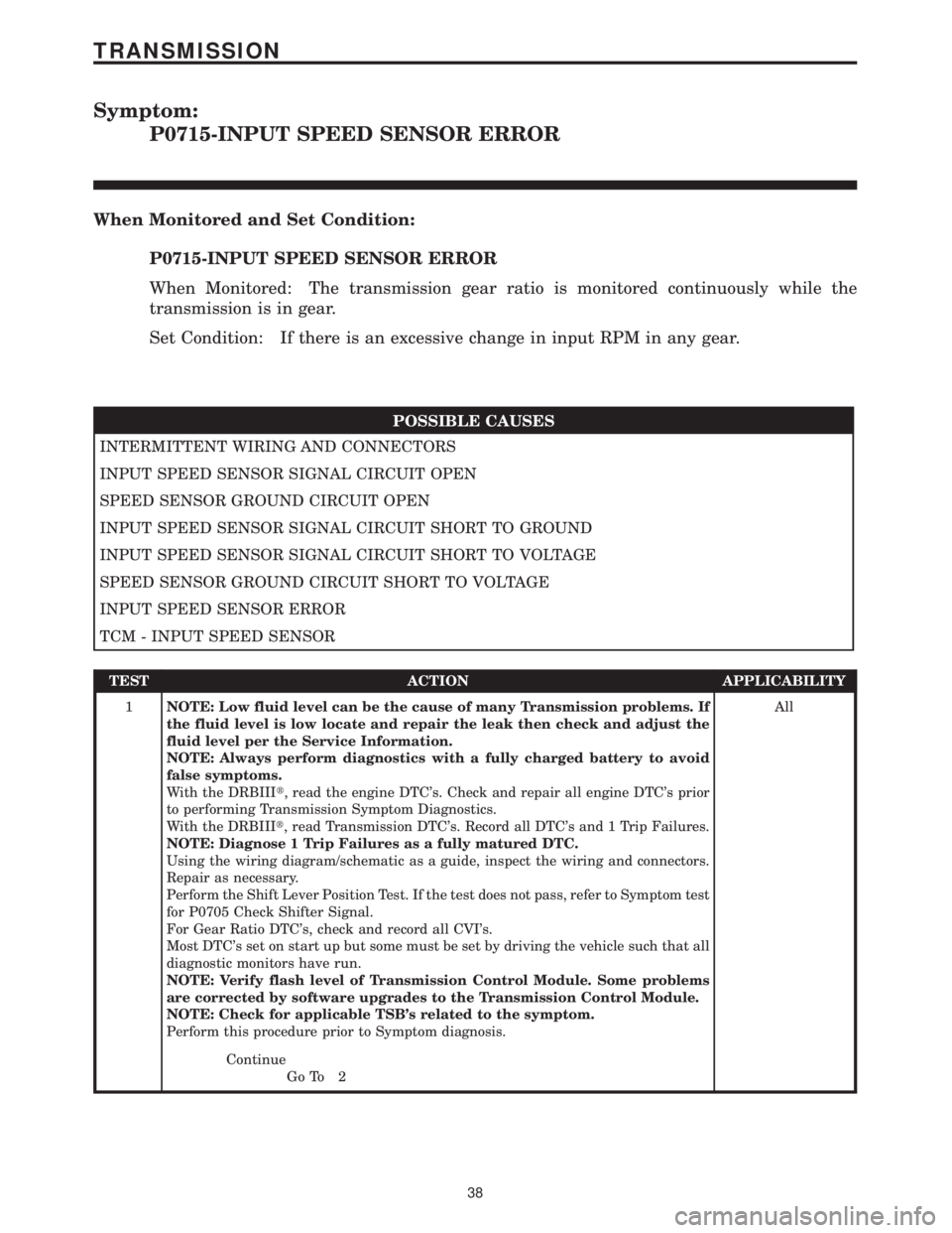
Symptom:
P0715-INPUT SPEED SENSOR ERROR
When Monitored and Set Condition:
P0715-INPUT SPEED SENSOR ERROR
When Monitored: The transmission gear ratio is monitored continuously while the
transmission is in gear.
Set Condition: If there is an excessive change in input RPM in any gear.
POSSIBLE CAUSES
INTERMITTENT WIRING AND CONNECTORS
INPUT SPEED SENSOR SIGNAL CIRCUIT OPEN
SPEED SENSOR GROUND CIRCUIT OPEN
INPUT SPEED SENSOR SIGNAL CIRCUIT SHORT TO GROUND
INPUT SPEED SENSOR SIGNAL CIRCUIT SHORT TO VOLTAGE
SPEED SENSOR GROUND CIRCUIT SHORT TO VOLTAGE
INPUT SPEED SENSOR ERROR
TCM - INPUT SPEED SENSOR
TEST ACTION APPLICABILITY
1NOTE: Low fluid level can be the cause of many Transmission problems. If
the fluid level is low locate and repair the leak then check and adjust the
fluid level per the Service Information.
NOTE: Always perform diagnostics with a fully charged battery to avoid
false symptoms.
With the DRBIIIt, read the engine DTC's. Check and repair all engine DTC's prior
to performing Transmission Symptom Diagnostics.
With the DRBIIIt, read Transmission DTC's. Record all DTC's and 1 Trip Failures.
NOTE: Diagnose 1 Trip Failures as a fully matured DTC.
Using the wiring diagram/schematic as a guide, inspect the wiring and connectors.
Repair as necessary.
Perform the Shift Lever Position Test. If the test does not pass, refer to Symptom test
for P0705 Check Shifter Signal.
For Gear Ratio DTC's, check and record all CVI's.
Most DTC's set on start up but some must be set by driving the vehicle such that all
diagnostic monitors have run.
NOTE: Verify flash level of Transmission Control Module. Some problems
are corrected by software upgrades to the Transmission Control Module.
NOTE: Check for applicable TSB's related to the symptom.
Perform this procedure prior to Symptom diagnosis.All
Continue
Go To 2
38
TRANSMISSION
Page 4146 of 4284
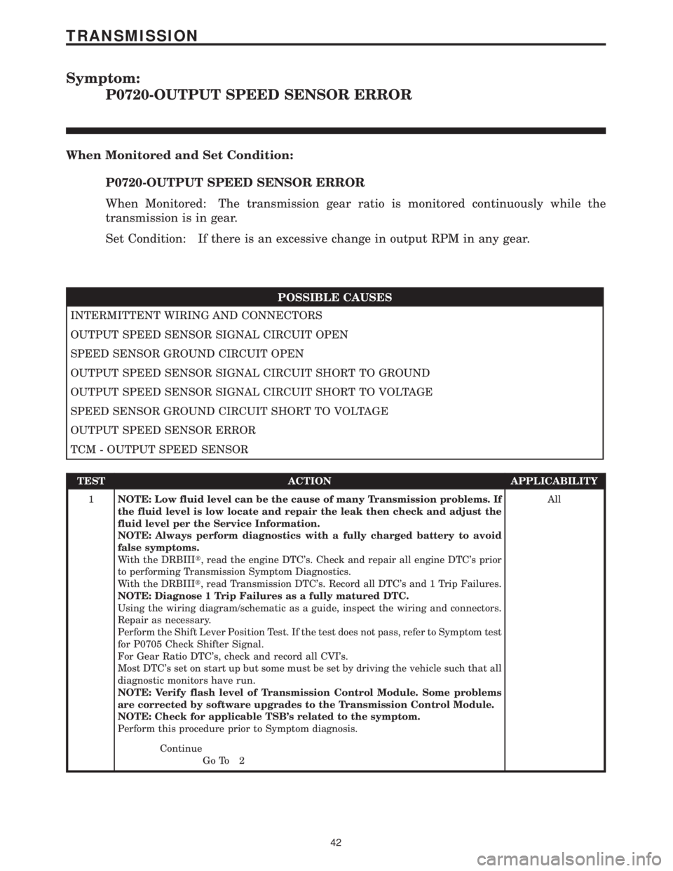
Symptom:
P0720-OUTPUT SPEED SENSOR ERROR
When Monitored and Set Condition:
P0720-OUTPUT SPEED SENSOR ERROR
When Monitored: The transmission gear ratio is monitored continuously while the
transmission is in gear.
Set Condition: If there is an excessive change in output RPM in any gear.
POSSIBLE CAUSES
INTERMITTENT WIRING AND CONNECTORS
OUTPUT SPEED SENSOR SIGNAL CIRCUIT OPEN
SPEED SENSOR GROUND CIRCUIT OPEN
OUTPUT SPEED SENSOR SIGNAL CIRCUIT SHORT TO GROUND
OUTPUT SPEED SENSOR SIGNAL CIRCUIT SHORT TO VOLTAGE
SPEED SENSOR GROUND CIRCUIT SHORT TO VOLTAGE
OUTPUT SPEED SENSOR ERROR
TCM - OUTPUT SPEED SENSOR
TEST ACTION APPLICABILITY
1NOTE: Low fluid level can be the cause of many Transmission problems. If
the fluid level is low locate and repair the leak then check and adjust the
fluid level per the Service Information.
NOTE: Always perform diagnostics with a fully charged battery to avoid
false symptoms.
With the DRBIIIt, read the engine DTC's. Check and repair all engine DTC's prior
to performing Transmission Symptom Diagnostics.
With the DRBIIIt, read Transmission DTC's. Record all DTC's and 1 Trip Failures.
NOTE: Diagnose 1 Trip Failures as a fully matured DTC.
Using the wiring diagram/schematic as a guide, inspect the wiring and connectors.
Repair as necessary.
Perform the Shift Lever Position Test. If the test does not pass, refer to Symptom test
for P0705 Check Shifter Signal.
For Gear Ratio DTC's, check and record all CVI's.
Most DTC's set on start up but some must be set by driving the vehicle such that all
diagnostic monitors have run.
NOTE: Verify flash level of Transmission Control Module. Some problems
are corrected by software upgrades to the Transmission Control Module.
NOTE: Check for applicable TSB's related to the symptom.
Perform this procedure prior to Symptom diagnosis.All
Continue
Go To 2
42
TRANSMISSION