Page 626 of 4284

TEST ACTION APPLICABILITY
7 Turn the ignition on.
With the DRBIIIt, erase Body Control Module DTCs.
Turn the ignition off to the lock position.
Disconnect the HVAC Module harness connector.
Turn the ignition on.
Turn the Headlamps on.
With the DRBIIIt, read DTCs.
Does the DRBIIItdisplay PANEL DIMMING OUTPUT SHORT?All
Ye s®Go To 8
No®Replace the HVAC Module in accordance with the Service Infor-
mation.
Perform BODY VERIFICATION TEST - VER 1.
8 Turn the ignition on.
With the DRBIIIt, erase Body Control Module DTCs.
Turn the ignition off to the lock position.
Disconnect the Radio harness connector.
Turn the ignition on.
Turn the Headlamps on.
With the DRBIIIt, read DTCs.
Does the DRBIIItdisplay PANEL DIMMING OUTPUT SHORT?All
Ye s®Go To 9
No®Replace the Radio in accordance with the Service Information.
Perform BODY VERIFICATION TEST - VER 1.
9 Turn the ignition off to the lock position.
Disconnect the Body Control Module harness connector.
Disconnect the EMIC harness connector.
Note: Check connectors - Clean/repair as necessary.
Measure the resistance between ground and the EMIC Dimming circuit.
Is the resistance below 5.0 ohms?All
Ye s®Repair the EMIC Dimming circuit for a short to ground.
Perform BODY VERIFICATION TEST - VER 1.
No®Go To 10
10 Turn the ignition off to the lock position.
Disconnect the Body Control Module harness connector.
Disconnect the Headlamp Switch harness connector.
Note: Check connectors - Clean/repair as necessary.
Measure the resistance between ground and the Headlamp Switch Dimming circuit.
Is the resistance below 5.0 ohms?All
Ye s®Repair the Headlamp Switch Dimming circuit for a short to
ground.
Perform BODY VERIFICATION TEST - VER 1.
No®Go To 11
597
INSTRUMENT CLUSTER
PANEL DIMMING OUTPUT SHORT ÐContinued
Page 627 of 4284

TEST ACTION APPLICABILITY
11 Turn the ignition off to the lock position.
Disconnect the Body Control Module harness connector.
Disconnect the HVAC Module harness connector.
Note: Check connectors - Clean/repair as necessary.
Measure the resistance between ground and the HVAC Module Dimming circuit.
Is the resistance below 5.0 ohms?All
Ye s®Repair the HVAC Module Dimming circuit for a short to ground.
Perform BODY VERIFICATION TEST - VER 1.
No®Go To 12
12 Turn the ignition off to the lock position.
Disconnect the Body Control Module harness connector.
Disconnect the I/P Multi-Function Switch harness connector.
Note: Check connectors - Clean/repair as necessary.
Measure the resistance between ground and the I/P Multi-Function Switch Dimming
circuit.
Is the resistance below 5.0 ohms?All
Ye s®Repair the I/P Multi-Function Switch Dimming circuit for a short
to ground.
Perform BODY VERIFICATION TEST - VER 1.
No®Go To 13
13 Turn the ignition off to the lock position.
Disconnect the Body Control Module harness connector.
Disconnect the Mirror Switch harness connector.
Note: Check connectors - Clean/repair as necessary.
Measure the resistance between ground and the Mirror Switch Dimming circuit.
Is the resistance below 5.0 ohms?All
Ye s®Repair the Mirror Switch Dimming circuit for a short to ground.
Perform BODY VERIFICATION TEST - VER 1.
No®Go To 14
14 Turn the ignition off to the lock position.
Disconnect the Body Control Module harness connector.
Disconnect the Rear Blower Control Switch harness connector.
Note: Check connectors - Clean/repair as necessary.
Measure the resistance between ground and the Rear Blower Control Switch
Dimming circuit.
Is the resistance below 5.0 ohms?All
Ye s®Repair the Rear Blower Control Switch Dimming circuit for a
short to ground.
Perform BODY VERIFICATION TEST - VER 1.
No®Go To 15
598
INSTRUMENT CLUSTER
PANEL DIMMING OUTPUT SHORT ÐContinued
Page 628 of 4284

TEST ACTION APPLICABILITY
15 Turn the ignition off to the lock position.
Disconnect the Body Control Module harness connector.
Disconnect the Radio harness connector.
Note: Check connectors - Clean/repair as necessary.
Measure the resistance between ground and the Radio Dimming circuit.
Is the resistance below 5.0 ohms?All
Ye s®Repair the Radio Dimming circuit for a short to ground.
Perform BODY VERIFICATION TEST - VER 1.
No®Go To 16
16 If there are no possible causes remaining, view repair. All
Repair
Replace the Body Control Module.
Perform BODY VERIFICATION TEST - VER 1.
17 The conditions necessary to set this DTC are not present at this time.
Using the schematics as a guide, inspect the wiring and connectors specific to this
circuit.
Wiggle the wiring while checking for shorts and open circuits.
Were there any problems found?All
Ye s®Repair as necessary.
Perform BODY VERIFICATION TEST - VER 1.
No®Test Complete.
599
INSTRUMENT CLUSTER
PANEL DIMMING OUTPUT SHORT ÐContinued
Page 1045 of 4284

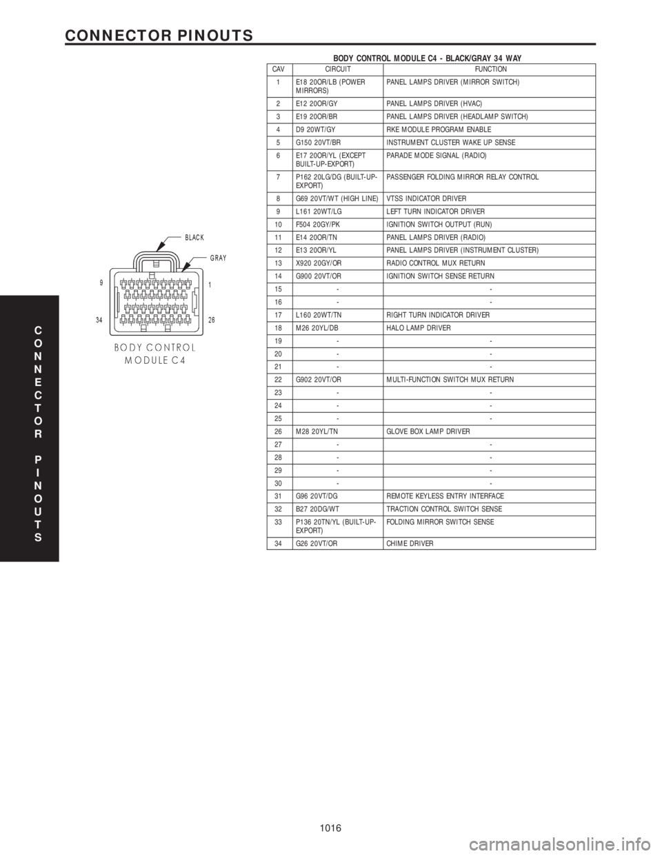
BODY CONTROL MODULE C4 - BLACK/GRAY 34 WAYCAV CIRCUIT FUNCTION
1 E18 20OR/LB (POWER
MIRRORS)PANEL LAMPS DRIVER (MIRROR SWITCH)
2 E12 20OR/GY PANEL LAMPS DRIVER (HVAC)
3 E19 20OR/BR PANEL LAMPS DRIVER (HEADLAMP SWITCH)
4 D9 20WT/GY RKE MODULE PROGRAM ENABLE
5 G150 20VT/BR INSTRUMENT CLUSTER WAKE UP SENSE
6 E17 20OR/YL (EXCEPT
BUILT-UP-EXPORT)PARADE MODE SIGNAL (RADIO)
7 P162 20LG/DG (BUILT-UP-
EXPORT)PASSENGER FOLDING MIRROR RELAY CONTROL
8 G69 20VT/WT (HIGH LINE) VTSS INDICATOR DRIVER
9 L161 20WT/LG LEFT TURN INDICATOR DRIVER
10 F504 20GY/PK IGNITION SWITCH OUTPUT (RUN)
11 E14 20OR/TN PANEL LAMPS DRIVER (RADIO)
12 E13 20OR/YL PANEL LAMPS DRIVER (INSTRUMENT CLUSTER)
13 X920 20GY/OR RADIO CONTROL MUX RETURN
14 G900 20VT/OR IGNITION SWITCH SENSE RETURN
15 - -
16 - -
17 L160 20WT/TN RIGHT TURN INDICATOR DRIVER
18 M26 20YL/DB HALO LAMP DRIVER
19 - -
20 - -
21 - -
22 G902 20VT/OR MULTI-FUNCTION SWITCH MUX RETURN
23 - -
24 - -
25 - -
26 M28 20YL/TN GLOVE BOX LAMP DRIVER
27 - -
28 - -
29 - -
30 - -
31 G96 20VT/DG REMOTE KEYLESS ENTRY INTERFACE
32 B27 20DG/WT TRACTION CONTROL SWITCH SENSE
33 P136 20TN/YL (BUILT-UP-
EXPORT)FOLDING MIRROR SWITCH SENSE
34 G26 20VT/OR CHIME DRIVER
C
O
N
N
E
C
T
O
R
P
I
N
O
U
T
S
1016
CONNECTOR PINOUTS
Page 1049 of 4284

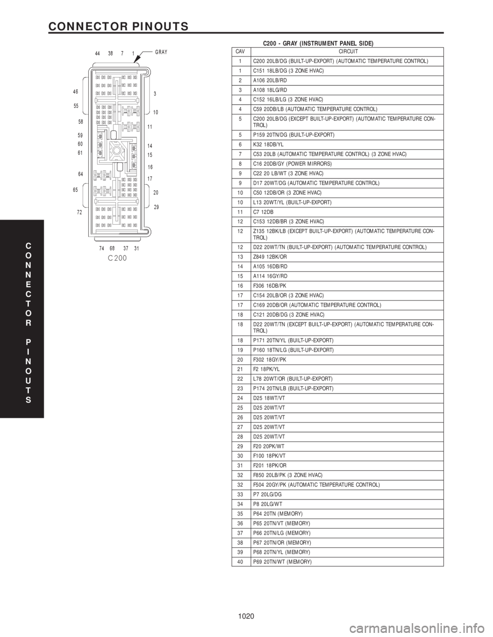
C200 - GRAY (INSTRUMENT PANEL SIDE)CAV CIRCUIT
1 C200 20LB/DG (BUILT-UP-EXPORT) (AUTOMATIC TEMPERATURE CONTROL)
1 C151 18LB/DG (3 ZONE HVAC)
2 A106 20LB/RD
3 A108 18LG/RD
4 C152 16LB/LG (3 ZONE HVAC)
4 C59 20DB/LB (AUTOMATIC TEMPERATURE CONTROL)
5 C200 20LB/DG (EXCEPT BUILT-UP-EXPORT) (AUTOMATIC TEMPERATURE CON-
TROL)
5 P159 20TN/DG (BUILT-UP-EXPORT)
6 K32 18DB/YL
7 C53 20LB (AUTOMATIC TEMPERATURE CONTROL) (3 ZONE HVAC)
8 C16 20DB/GY (POWER MIRRORS)
9 C22 20 LB/WT (3 ZONE HVAC)
9 D17 20WT/DG (AUTOMATIC TEMPERATURE CONTROL)
10 C50 12DB/OR (3 ZONE HVAC)
10 L13 20WT/YL (BUILT-UP-EXPORT)
11 C7 12DB
12 C153 12DB/BR (3 ZONE HVAC)
12 Z135 12BK/LB (EXCEPT BUILT-UP-EXPORT) (AUTOMATIC TEMPERATURE CON-
TROL)
12 D22 20WT/TN (BUILT-UP-EXPORT) (AUTOMATIC TEMPERATURE CONTROL)
13 Z849 12BK/OR
14 A105 16DB/RD
15 A114 16GY/RD
16 F306 16DB/PK
17 C154 20LB/OR (3 ZONE HVAC)
17 C169 20DB/OR (AUTOMATIC TEMPERATURE CONTROL)
18 C121 20DB/DG (3 ZONE HVAC)
18 D22 20WT/TN (EXCEPT BUILT-UP-EXPORT) (AUTOMATIC TEMPERATURE CON-
TROL)
18 P171 20TN/YL (BUILT-UP-EXPORT)
19 P160 18TN/LG (BUILT-UP-EXPORT)
20 F302 18GY/PK
21 F2 18PK/YL
22 L78 20WT/OR (BUILT-UP-EXPORT)
23 P174 20TN/LB (BUILT-UP-EXPORT)
24 D25 18WT/VT
25 D25 20WT/VT
26 D25 20WT/VT
27 D25 20WT/VT
28 D25 20WT/VT
29 F20 20PK/WT
30 F100 18PK/VT
31 F201 18PK/OR
32 F850 20LB/PK (3 ZONE HVAC)
32 F504 20GY/PK (AUTOMATIC TEMPERATURE CONTROL)
33 P7 20LG/DG
34 P8 20LG/WT
35 P64 20TN (MEMORY)
36 P65 20TN/VT (MEMORY)
37 P66 20TN/LG (MEMORY)
38 P67 20TN/OR (MEMORY)
39 P68 20TN/YL (MEMORY)
40 P69 20TN/WT (MEMORY)
C
O
N
N
E
C
T
O
R
P
I
N
O
U
T
S
1020
CONNECTOR PINOUTS
Page 1050 of 4284

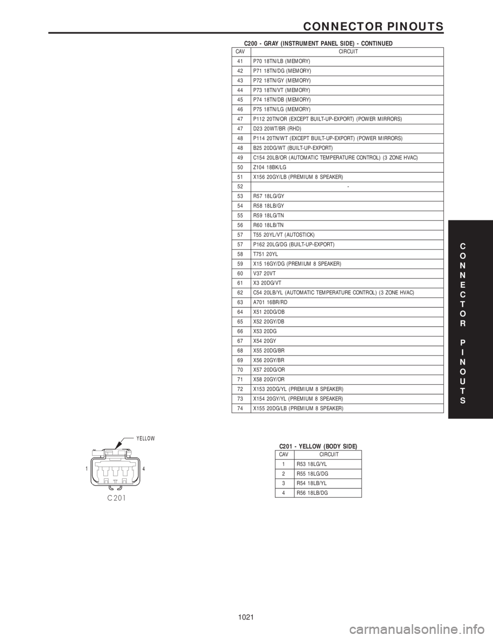
C200 - GRAY (INSTRUMENT PANEL SIDE) - CONTINUEDCAV CIRCUIT
41 P70 18TN/LB (MEMORY)
42 P71 18TN/DG (MEMORY)
43 P72 18TN/GY (MEMORY)
44 P73 18TN/VT (MEMORY)
45 P74 18TN/DB (MEMORY)
46 P75 18TN/LG (MEMORY)
47 P112 20TN/OR (EXCEPT BUILT-UP-EXPORT) (POWER MIRRORS)
47 D23 20WT/BR (RHD)
48 P114 20TN/WT (EXCEPT BUILT-UP-EXPORT) (POWER MIRRORS)
48 B25 20DG/WT (BUILT-UP-EXPORT)
49 C154 20LB/OR (AUTOMATIC TEMPERATURE CONTROL) (3 ZONE HVAC)
50 Z104 18BK/LG
51 X156 20GY/LB (PREMIUM 8 SPEAKER)
52 -
53 R57 18LG/GY
54 R58 18LB/GY
55 R59 18LG/TN
56 R60 18LB/TN
57 T55 20YL/VT (AUTOSTICK)
57 P162 20LG/DG (BUILT-UP-EXPORT)
58 T751 20YL
59 X15 16GY/DG (PREMIUM 8 SPEAKER)
60 V37 20VT
61 X3 20DG/VT
62 C54 20LB/YL (AUTOMATIC TEMPERATURE CONTROL) (3 ZONE HVAC)
63 A701 16BR/RD
64 X51 20DG/DB
65 X52 20GY/DB
66 X53 20DG
67 X54 20GY
68 X55 20DG/BR
69 X56 20GY/BR
70 X57 20DG/OR
71 X58 20GY/OR
72 X153 20DG/YL (PREMIUM 8 SPEAKER)
73 X154 20GY/YL (PREMIUM 8 SPEAKER)
74 X155 20DG/LB (PREMIUM 8 SPEAKER)
C201 - YELLOW (BODY SIDE)CAV CIRCUIT
1 R53 18LG/YL
2 R55 18LG/DG
3 R54 18LB/YL
4 R56 18LB/DG
C
O
N
N
E
C
T
O
R
P
I
N
O
U
T
S
1021
CONNECTOR PINOUTS
Page 1051 of 4284
C201 - YELLOW (INSTRUMENT PANEL SIDE)CAV CIRCUIT
1 R53 18LG/YL
2 R55 18LG/DG
3 R54 18LB/YL
4 R56 18LB/DG
C202 - GRAY (COMPONENT SIDE)CAV CIRCUIT
1 Z134 12BK/OR (AUTOMATIC
TEMPERATURE CONTROL)
2 C34 20DB/LB (MANUAL
TEMPERATURE CONTROL)
2 C56 20DB/LB (AUTOMATIC
TEMPERATURE CONTROL)
3 C32 20DB/TN
4 C33 20LB/BR
5 C61 20LB/WT (MTC)
5 C61 20DB/LG (ATC)
6 C35 20LB/OR
7 C7 12DB (AUTOMATIC
TEMPERATURE CONTROL)
8 C132 20DB/YL (AUTOMATIC
TEMPERATURE CONTROL)
9 C133 20DB/WT (AUTOMAT-
IC TEMPERATURE CON-
TROL)
10 C161 20LB/WT (AUTOMAT-
IC TEMPERATURE CON-
TROL)
11 C135 20DB/GY (AUTOMAT-
IC TEMPERATURE CON-
TROL)
12 C21 20DB/LG
13 C121 20DB/DG
C
O
N
N
E
C
T
O
R
P
I
N
O
U
T
S
1022
CONNECTOR PINOUTS
Page 1052 of 4284
C202 - GRAY (INSTRUMENT PANEL SIDE)CAV CIRCUIT
1 Z134 12BK/OR (AUTOMATIC
TEMPERATURE CONTROL)
2 C34 20DB/LB (MANUAL
TEMPERATURE CONTROL)
2 C56 20DB/LB (AUTOMATIC
TEMPERATURE CONTROL)
3 C32 20DB/TN
4 C33 20LB/BR
5 C61 20DB/LG
6 C35 20LB/OR
7 C7 12DB (AUTOMATIC
TEMPERATURE CONTROL)
8 C132 20DB/YL (AUTOMATIC
TEMPERATURE CONTROL)
9 C133 20DB/WT (AUTOMAT-
IC TEMPERATURE CON-
TROL)
10 C161 20LB/WT (AUTOMAT-
IC TEMPERATURE CON-
TROL)
11 C135 20DB/GY (AUTOMAT-
IC TEMPERATURE CON-
TROL)
12 C21 20DB/LG
13 C121 20DB/DG
C304 - YELLOW (BODY SIDE)CAV CIRCUIT
1 R54 18LB/YL (RHD)
1 R53 18LG/YL (LHD)
2 R56 18LB/DG (RHD)
2 R55 18LG/DG (LHD)
3 R31 18LG/OR
4 R33 18LG/WT
C304 - YELLOW (SEAT SIDE)CAV CIRCUIT
1 R54 18LB/YL (RHD)
1 R53 18LG/YL (LHD)
2 R56 18LB/DG (RHD)
2 R55 18LG/DG (LHD)
3 R31 18LG/OR
4 R33 18LG/WT
C
O
N
N
E
C
T
O
R
P
I
N
O
U
T
S
1023
CONNECTOR PINOUTS