2001 CHRYSLER VOYAGER engine coolant
[x] Cancel search: engine coolantPage 3740 of 4284
INSTALLATION
(1) Install both flexible coolant lines to the heater
unit and install clamps.
(2) Install flexible coolant lines to the coolant pipes
and install clamps.
(3) Install heater unit into vehicle(Refer to 24 -
HEATING & AIR CONDITIONING/CABIN HEAT-
ER/HEATER UNIT - INSTALLATION).
(4) Lower vehicle.
(5) Refill cooling system(Refer to 7 - COOLING -
STANDARD PROCEDURE).
(6) Verify operation of heater unit.
HEATER PIPES - DIESEL
SUPPLEMENTAL HEATER
REMOVAL
CAUTION: Allow cooling system to cool completely
before removing radiator cap or draining cooling
system. Injury could result is system is opened
while system coolant is hot and under pressure.
NOTE: Steel heater lines from engine compartment
to heater unit are part of an assembly that includes
the air intake pipe. If the heater lines or air intake
pipe require removal or replacement the entire
assembly must be removed or replaced.
(1) Open hood.
(2) Drain the cooling system(Refer to 7 - COOL-
ING - STANDARD PROCEDURE).
(3) Remove clamps from both the EGR cooler and
the lower heater port. Separate hoses from the mat-
ing plumbing port. (Fig. 1).
(4) Remove retaining nut from heater line under
hood bracket.(5) Elevate vehicle on a lift.
NOTE: When supporting vehicle care should be
taken not to damage the heater exhaust tube.
(6) Remove clamps from heater lines to the rubber
connection nearest the tubes. Separate the hoses
from the tube assembly leaving the rubber hose
attached to the supplemental heater.
(7) Remove heater unit intake pipe from heater-
(Refer to 24 - HEATING & AIR CONDITIONING/
CABIN HEATER/INLET HOSE - REMOVAL) (Fig.
2).
(8) Remove heater pipe assembly retaining screws
and remove assembly from vehicle.
INSTALLATION
(1) With vehicle on a lift position the heater pipe
assembly and install the retaining screws.
(2) Install the heater unit intake pipe to the
heater unit(Refer to 24 - HEATING & AIR CONDI-
TIONING/CABIN HEATER/INLET HOSE - INSTAL-
LATION).
(3) Connect heater hoses to the heater unit and
tighten the clamps.
(4) Install heater unit intake pipe to heater uni-
t(Refer to 24 - HEATING & AIR CONDITIONING/
CABIN HEATER/INLET HOSE - INSTALLATION).
(5) Lower vehicle on lift.
(6) Install retaining nut to heater line under hood
bracket and tighten.
(7) Connect heater lines to heater hoses at heater
core and EGR port. Position spring clamps onto the
installed hoses.
(8) Refill cooling system(Refer to 7 - COOLING -
STANDARD PROCEDURE).
(9) Close hood.
24a - 2 HEATING & AIR CONDITIONINGRG
HEATER HOSES - DIESEL SUPPLEMENTAL HEATER (Continued)
Page 3743 of 4284
(4) Raise the liquid line (discharge) pressure to
about 1793 kPa (260 psi) by placing a piece of card-
board over part of the front side of the condenser. To
place the cardboard properly, remove the upper radi-
ator sight shield from the front fascia. Cover only
enough of the condenser to raise and maintain the
liquid line pressure at the specified level.
(5) Observe the liquid line (discharge) pressure
and liquid line temperature. Using the Charge Deter-
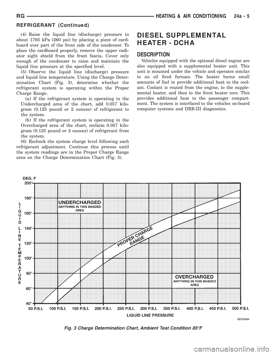
mination Chart (Fig. 3), determine whether the
refrigerant system is operating within the Proper
Charge Range.
(a) If the refrigerant system is operating in the
Undercharged area of the chart, add 0.057 kilo-
gram (0.125 pound or 2 ounces) of refrigerant to
the system.
(b) If the refrigerant system is operating in the
Overcharged area of the chart, reclaim 0.057 kilo-
gram (0.125 pound or 2 ounces) of refrigerant from
the system.
(6) Recheck the system charge level following each
refrigerant adjustment. Continue this process until
the system readings are in the Proper Charge Range
area on the Charge Determination Chart (Fig. 3).DIESEL SUPPLEMENTAL
HEATER - DCHA
DESCRIPTION
Vehicles equipped with the optional diesel engine are
also equipped with a supplemental heater unit. This
unit is mounted under the vehicle and operates similar
to an oil fired furnace. The heater burns small
amounts of fuel to provide additional heat to the cool-
ant. Coolant is routed from the engine, to the supple-
mental heater, and then to the front heater core. This
provides additional heat to the passenger compart-
ment. The system is interfaced to the vehicles on-board
computer systems and DRB-III diagnostics.
Fig. 3 Charge Determination Chart, Ambient Test Condition 85ÉF
RGHEATING & AIR CONDITIONING24a-5
REFRIGERANT (Continued)
Page 3744 of 4284
OPERATION
The supplemental heater unit is activated via the
temperature slide control or knob on the vehicle HVAC
control unit. If the control slide or knob is moved to or
above the upper set point the heater is activated. The
unit can operate in a full or partial load range as well
as an idle mode all dependent on the engine coolanttemperature. The heater unit will also turn off if the
HVAC temperature control is lowered to less than the
lower set point. The heater unit can take up to three
minutes to completely shut down when either the
heater temperature is set below the lower set point or
the vehicle ignition is shut down.
DIAGNOSIS AND TESTING - DIESEL SUPPLEMENTAL HEATER - DCHA
The following table lists possible fault symptoms of
diesel fueled heaters.
SYMPTOM POSSIBLE CAUSES
Smell of diesel fuel Check heater system integration in vehicle's fuel system. Check fuel
lines for leakage, kinks or obstructions. If OK, Inspect the inlet muffler,
drain as necessary. Re-test the unit and re-inspect. Inspect the
exhaust tube and heater unit for the presence of external fuel. If a
volume is observed on the unit or in the exhaust tube or after draining
and testing. Remove heater unit from vehicle and repair or replace
components as required.
Heater does not achieve full load
operation.Check heater operation with DRB-III and replace components as
required.
Continuous white smoke from heater
exhaust during combustion operation.Check heater operation with DRB-III and replace components as
required. White smoke is typical in extreme weather conditions.
Heater can not be switched off. Check heater operation with DRB-III and replace components as
required.
Heater does not operate. Diagnosis cabin heater ECU using the DRB-III and the procedures
listed in Vehicle Performance under Cabin Heater Diagnosis in Group
18.
Loss of coolant (Leakage) or heater
develops smoke during combustion
operation and exhaust has an
extremely sweet smell.Inspect coolant hoses for leakage, kinks or loose hose connection.
Inspect the exhaust tube assembly for continuous flow, if OK there is
an internal heater leak and unit should be inspected and components
should be replaced as required.
Loss of fuel (dripping). Check heater system integration in vehicles fuel system. Check fuel
line connection for leakage. If OK there is an internal leak and unit
should be inspected and replaced as required.
EXHAUST TUBE
REMOVAL
WARNING: THERE IS A POTENTIAL DANGER OF
SKIN BURNS AS THE HEATER AND ITS COMPO-
NENTS MAY BE VERY HOT. MAKE SURE THE
HEATER IS ALLOWED TO COOL DOWN BEFORE
ANY SERVICE WORK IS ATTEMPTED.
WARNING: THERE IS A POTENTIAL DANGER OF
SKIN BURNS AS THE EXHAUST SYSTEM MAY BE
VERY HOT. MAKE SURE THE EXHAUST SYSTEM ISALLOWED TO COOL DOWN BEFORE ANY SERVICE
WORK IS ATTEMPTED ON THE CABIN HEATER.
(1) Elevate vehicle on a lift taking note of the
exhaust tube flexible section.
(2) Remove the exhaust clamp at the flexible pipe
and steel pipe connection (Fig. 4).
(3) Remove the clamp at the flexible pipe connec-
tion and the heater unit housing (if required).
(4) Remove the three screws holding the exhaust
pipe to the body.
(5) Remove the steel exhaust pipe from the vehi-
cle.
(6) Remove the flexible exhaust pipe from the
vehicle (if required).
24a - 6 HEATING & AIR CONDITIONINGRG
DIESEL SUPPLEMENTAL HEATER - DCHA (Continued)
Page 3751 of 4284
EMISSIONS CONTROL
TABLE OF CONTENTS
page page
EMISSIONS CONTROL
DESCRIPTION............................1
OPERATION.............................8EVAPORATIVE EMISSIONS.................10
EXHAUST GAS RECIRCULATION............20
ON-BOARD DIAGNOSTICS.................23
EMISSIONS CONTROL
DESCRIPTION - MONITORED COMPONENT
There are several components that will affect vehi-
cle emissions if they malfunction. If one of these com-
ponents malfunctions the Malfunction Indicator
Lamp (Check Engine) will illuminate.
Some of the component monitors are checking for
proper operation of the part. Electrically operated
components now have input (rationality) and output
(functionality) checks. Previously, a component like
the Throttle Position sensor (TPS) was checked by
the PCM for an open or shorted circuit. If one of
these conditions occurred, a DTC was set. Now there
is a check to ensure that the component is working.
This is done by watching for a TPS indication of a
greater or lesser throttle opening than MAP and
engine rpm indicate. In the case of the TPS, if engine
vacuum is high and engine rpm is 1600 or greater
and the TPS indicates a large throttle opening, a
DTC will be set. The same applies to low vacuum
and 1600 rpm.Any component that has an associated
limp in will set a fault after 1 trip with the malfunc-
tion present.
Refer to the Diagnostic Trouble Codes Description
Charts in this section and the appropriate Power-
train Diagnostic Procedure Manual for diagnostic
procedures.
The following is a list of the monitored compo-
nents:
²Comprehensive Components
²Oxygen Sensor Monitor
²Oxygen Sensor Heater Monitor
²Catalyst Monitor
COMPREHENSIVE COMPONENTS
Along with the major monitors, OBD II requires
that the diagnostic system monitor any component
that could affect emissions levels. In many cases,
these components were being tested under OBD I.
The OBD I requirements focused mainly on testing
emissions-related components for electrical opens and
shorts.However, OBD II also requires that inputs from
powertrain components to the PCM be tested for
rationality, and that outputs to powertrain compo-
nents from the PCM be tested forfunctionality.
Methods for monitoring the various Comprehensive
Component monitoring include:
(1) Circuit Continuity
²Open
²Shorted high
²Shorted to ground
(2) Rationality or Proper Functioning
²Inputs tested for rationality
²Outputs tested for functionality
NOTE: Comprehensive component monitors are
continuous. Therefore, enabling conditions do not
apply.
Input RationalityÐWhile input signals to the
PCM are constantly being monitored for electrical
opens and shorts, they are also tested for rationality.
This means that the input signal is compared against
other inputs and information to see if it makes sense
under the current conditions.
PCM sensor inputs that are checked for rationality
include:
²Manifold Absolute Pressure (MAP) Sensor
²Oxygen Sensor (O2S)
²Engine Coolant Temperature (ECT) Sensor
²Camshaft Position (CMP) Sensor
²Vehicle Speed Sensor
²Crankshaft Position (CKP) Sensor
²Intake Air Temperature (IAT) Sensor
²Throttle Position (TPS) Sensor
²Ambient/Battery Temperature Sensors
²Power Steering Switch
²Oxygen Sensor Heater
²Engine Controller
²Brake Switch
²Leak Detection Pump Switch
²P/N Switch
²Trans Controls
Output FunctionalityÐPCM outputs are tested
for functionality in addition to testing for opens and
shorts. When the PCM provides a voltage to an out-
RSEMISSIONS CONTROL25-1
Page 3753 of 4284
²Vehicle Speed Sensor
²Engine Coolant Temperature Sensor
²Throttle Position Sensor
²Engine Controller Self Test Faults
²Cam or Crank Sensor
²Injector and Coil
²Idle Air Control Motor
²EVAP Electrical
²EGR Solenoid Electrical
²Intake Air Temperature
²5 Volt Feed
ConflictÐThe Task Manager does not run the
Oxygen Sensor Monitor if any of the following condi-
tions are present:
²A/C ON (A/C clutch cycling temporarily sus-
pends monitor)
²Purge flow in progress
²Ethanel content learn is takeng place and the
ethenal used once flag is set
SuspendÐThe Task Manager suspends maturing
a fault for the Oxygen Sensor Monitor if an of the fol-
lowing are present:
²Oxygen Sensor Heater Monitor, Priority 1
²Misfire Monitor, Priority 2
OXYGEN SENSOR HEATER MONITOR
DESCRIPTIONÐIf there is an oxygen sensor
(O2S) DTC as well as a O2S heater DTC, the O2S
fault MUST be repaired first. After the O2S fault is
repaired, verify that the heater circuit is operating
correctly.
The voltage readings taken from the O2S are very
temperature sensitive. The readings are not accurate
below 300ÉC. Heating of the O2S is done to allow the
engine controller to shift to closed loop control as
soon as possible. The heating element used to heat
the O2S must be tested to ensure that it is heating
the sensor properly.
The heater element itself is not tested. The sensor
output is used to test the heater by isolating the
effect of the heater element on the O2S output volt-
age from the other effects. The resistance is normally
between 100 ohms and 4.5 megaohms. When oxygen
sensor temperature increases, the resistance in the
internal circuit decreases. The PCM sends a 5 volts
biased signal through the oxygen sensors to ground
this monitoring circuit. As the temperature increases,
resistance decreases and the PCM detects a lower
voltage at the reference signal. Inversely, as the tem-
perature decreases, the resistance increases and the
PCM detects a higher voltage at the reference signal.
The O2S circuit is monitored for a drop in voltage.
OPERATIONÐThe Oxygen Sensor Heater Moni-
tor begins after the ignition has been turned OFF
and the O2 sensors have cooled. The PCM sends a 5
volt bias to the oxygen sensor every 1.6 seconds. ThePCM keeps it biased for 35 ms each time. As the sen-
sor cools down, the resistance increases and the PCM
reads the increase in voltage. Once voltage has
increased to a predetermined amount, higher than
when the test started, the oxygen sensor is cool
enough to test heater operation.
When the oxygen sensor is cool enough, the PCM
energizes the ASD relay. Voltage to the O2 sensor
begins to increase the temperature. As the sensor
temperature increases, the internal resistance
decreases. The PCM continues biasing the 5 volt sig-
nal to the sensor. Each time the signal is biased, the
PCM reads a voltage decrease. When the PCM
detects a voltage decrease of a predetermined value
for several biased pulses, the test passes.
The heater elements are tested each time the
engine is turned OFF if all the enabling conditions
are met. If the monitor fails, the PCM stores a
maturing fault and a Freeze Frame is entered. If two
consecutive tests fail, a DTC is stored. Because the
ignition is OFF, the MIL is illuminated at the begin-
ning of the next key cycle.
Enabling ConditionsÐThe following conditions
must be met for the PCM to run the oxygen sensor
heater test:
²Engine run time of at least 5.1 minutes
²Key OFF power down
²Battery voltage of at least 10 volts
²Sufficient Oxygen Sensor cool down
Pending ConditionsÐThere are not conditions or
situations that prompt conflict or suspension of test-
ing. The oxygen sensor heater test is not run pending
resolution of MIL illumination due to oxygen sensor
failure.
SuspendÐThere are no conditions which exist for
suspending the Heater Monitor.
CATALYST MONITOR
To comply with clean air regulations, vehicles are
equipped with catalytic converters. These converters
reduce the emission of hydrocarbons, oxides of nitro-
gen and carbon monoxide.
Normal vehicle miles or engine misfire can cause a
catalyst to decay. A meltdown of the ceramic core can
cause a reduction of the exhaust passage. This can
increase vehicle emissions and deteriorate engine
performance, driveability and fuel economy.
The catalyst monitor uses dual oxygen sensors
(O2S's) to monitor the efficiency of the converter. The
dual O2S strategy is based on the fact that as a cat-
alyst deteriorates, its oxygen storage capacity and its
efficiency are both reduced. By monitoring the oxy-
gen storage capacity of a catalyst, its efficiency can
be indirectly calculated. The upstream O2S is used to
detect the amount of oxygen in the exhaust gas
before the gas enters the catalytic converter. The
RSEMISSIONS CONTROL25-3
EMISSIONS CONTROL (Continued)
Page 3754 of 4284
PCM calculates the A/F mixture from the output of
the O2S. A low voltage indicates high oxygen content
(lean mixture). A high voltage indicates a low content
of oxygen (rich mixture).
When the upstream O2S detects a lean condition,
there is an abundance of oxygen in the exhaust gas.
A functioning converter would store this oxygen so it
can use it for the oxidation of HC and CO. As the
converter absorbs the oxygen, there will be a lack of
oxygen downstream of the converter. The output of
the downstream O2S will indicate limited activity in
this condition.
As the converter loses the ability to store oxygen,
the condition can be detected from the behavior of
the downstream O2S. When the efficiency drops, no
chemical reaction takes place. This means the con-
centration of oxygen will be the same downstream as
upstream. The output voltage of the downstream
O2S copies the voltage of the upstream sensor. The
only difference is a time lag (seen by the PCM)
between the switching of the O2S's.
To monitor the system, the number of lean-to-rich
switches of upstream and downstream O2S's is
counted. The ratio of downstream switches to
upstream switches is used to determine whether the
catalyst is operating properly. An effective catalyst
will have fewer downstream switches than it has
upstream switches i.e., a ratio closer to zero. For a
totally ineffective catalyst, this ratio will be one-to-
one, indicating that no oxidation occurs in the device.
The system must be monitored so that when cata-
lyst efficiency deteriorates and exhaust emissions
increase to over the legal limit, the MIL (check
engine lamp) will be illuminated.
Monitor OperationÐTo monitor catalyst effi-
ciency, the PCM expands the rich and lean switch
points of the heated oxygen sensor. With extended
switch points, the air/fuel mixture runs richer and
leaner to overburden the catalytic converter. Once
the test is started, the air/fuel mixture runs rich and
lean and the O2 switches are counted. A switch is
counted when an oxygen sensor signal goes from
below the lean threshold to above the rich threshold.
The number of Rear O2 sensor switches is divided by
the number of Front O2 sensor switches to determine
the switching ratio.
The test runs for 20 seconds. As catalyst efficiency
deteriorated over the life of the vehicle, the switch
rate at the downstream sensor approaches that of the
upstream sensor. If at any point during the test
period the switch ratio reaches a predetermined
value, a counter is incremented by one. The monitor
is enabled to run another test during that trip. When
the test fails three times, the counter increments to
three, a malfunction is entered, and a Freeze Frame
is stored. When the counter increments to three dur-ing the next trip, the code is matured and the MIL is
illuminated. If the test passes the first, no further
testing is conducted during that trip.
The MIL is extinguished after three consecutive
good trips. The good trip criteria for the catalyst
monitor is more stringent than the failure criteria. In
order to pass the test and increment one good trip,
the downstream sensor switch rate must be less than
80% of the upstream rate (60% for manual transmis-
sions). The failure percentages are 90% and 70%
respectively.
Enabling ConditionsÐThe following conditions
must typically be met before the PCM runs the cat-
alyst monitor. Specific times for each parameter may
be different from engine to engine.
²Accumulated drive time
²Enable time
²Ambient air temperature
²Barometric pressure
²Catalyst warm-up counter
²Engine coolant temperature
²Accumulated throttle position sensor
²Vehicle speed
²MAP
²RPM
²Engine in closed loop
²Fuel level
Pending ConditionsÐ
²Misfire DTC
²Front Oxygen Sensor Response
²Front Oxygen Sensor Heater Monitor
²Front Oxygen Sensor Electrical
²Rear Oxygen Sensor Rationality (middle check)
²Rear Oxygen Sensor Heater Monitor
²Rear Oxygen Sensor Electrical
²Fuel System Monitor
²All TPS faults
²All MAP faults
²All ECT sensor faults
²Purge flow solenoid functionality
²Purge flow solenoid electrical
²All PCM self test faults
²All CMP and CKP sensor faults
²All injector and ignition electrical faults
²Idle Air Control (IAC) motor functionality
²Vehicle Speed Sensor
²Brake switch
²Intake air temperature
ConflictÐThe catalyst monitor does not run if any
of the following are conditions are present:
²EGR Monitor in progress
²Fuel system rich intrusive test in progress
²EVAP Monitor in progress
²Time since start is less than 60 seconds
²Low fuel level
²Low ambient air temperature
25 - 4 EMISSIONS CONTROLRS
EMISSIONS CONTROL (Continued)
Page 3755 of 4284
²Ethanel content learn is takeng place and the
ethenal used once flag is set
SuspendÐThe Task Manager does not mature a
catalyst fault if any of the following are present:
²Oxygen Sensor Monitor, Priority 1
²Upstream Oxygen Sensor Heater, Priority 1
²EGR Monitor, Priority 1
²EVAP Monitor, Priority 1
²Fuel System Monitor, Priority 2
²Misfire Monitor, Priority 2
DESCRIPTION - VEHICLE EMISSION CONTROL
INFORMATION LABEL
All models have a Vehicle Emission Control Infor-
mation (VECI) Label. Chrysler permanently attaches
the label in the engine compartment. It cannot be
removed without defacing information and destroying
the label.
The label contains the vehicle's emission specifica-
tions and vacuum hose routings. All hoses must be
connected and routed according to the label.
DESCRIPTION - TRIP DEFINITION
A ªTripº means vehicle operation (following an
engine-off period) of duration and driving mode such
that all components and systems are monitored at
least once by the diagnostic system. The monitors
must successfully pass before the PCM can verify
that a previously malfunctioning component is meet-
ing the normal operating conditions of that compo-
nent. For misfire or fuel system malfunction, the
MIL may be extinguished if the fault does not recur
when monitored during three subsequent sequential
driving cycles in which conditions are similar to
those under which the malfunction was first deter-
mined.
Anytime the MIL is illuminated, a DTC is stored.
The DTC can self erase only when the MIL has been
extinguished. Once the MIL is extinguished, the
PCM must pass the diagnostic test for the most
recent DTC for 40 warm-up cycles (80 warm-up
cycles for the Fuel System Monitor and the Misfire
Monitor) . A warm-up cycle can best be described by
the following:
²The engine must be running
²A rise of 40ÉF in engine temperature must occur
from the time when the engine was started
²Engine coolant temperature must reach at least
160ÉF
²A ªdriving cycleº that consists of engine start up
and engine shut off.
Once the above conditions occur, the PCM is con-
sidered to have passed a warm-up cycle. Due to the
conditions required to extinguish the MIL and erase
the DTC, it is most important that after a repair hasbeen made, all DTC's be erased and the repair veri-
fied.
OPERATION - NON-MONITORED CIRCUITS
The PCM does not monitor all circuits, systems
and conditions that could have malfunctions causing
driveability problems. However, problems with these
systems may cause the PCM to store diagnostic trou-
ble codes for other systems or components. For exam-
ple, a fuel pressure problem will not register a fault
directly, but could cause a rich/lean condition or mis-
fire. This could cause the PCM to store an oxygen
sensor or misfire diagnostic trouble code.
The major non-monitored circuits are listed below
along with examples of failures modes that do not
directly cause the PCM to set a DTC, but for a sys-
tem that is monitored.
FUEL PRESSURE
The fuel pressure regulator controls fuel system
pressure. The PCM cannot detect a clogged fuel
pump inlet filter, clogged in-line fuel filter, or a
pinched fuel supply or return line. However, these
could result in a rich or lean condition causing the
PCM to store an oxygen sensor or fuel system diag-
nostic trouble code.
SECONDARY IGNITION CIRCUIT
The PCM cannot detect an inoperative ignition coil,
fouled or worn spark plugs, ignition cross firing, or
open spark plug cables.
CYLINDER COMPRESSION
The PCM cannot detect uneven, low, or high engine
cylinder compression.
EXHAUST SYSTEM
The PCM cannot detect a plugged, restricted or
leaking exhaust system. It may set a EGR or Fuel
system fault or O2S.
FUEL INJECTOR MECHANICAL MALFUNCTIONS
The PCM cannot determine if a fuel injector is
clogged, the needle is sticking or if the wrong injector
is installed. However, these could result in a rich or
lean condition causing the PCM to store a diagnostic
trouble code for either misfire, an oxygen sensor, or
the fuel system.
EXCESSIVE OIL CONSUMPTION
Although the PCM monitors engine exhaust oxygen
content when the system is in closed loop, it cannot
determine excessive oil consumption.
THROTTLE BODY AIR FLOW
The PCM cannot detect a clogged or restricted air
cleaner inlet or filter element.
RSEMISSIONS CONTROL25-5
EMISSIONS CONTROL (Continued)
Page 3775 of 4284
Major Monitors. If the Task Manager cannot run a
Global Good Trip because a component fault is stop-
ping the monitor from running, it will attempt to
count an Alternate Good Trip.
The Task Manager counts an Alternate Good Trip
for Comprehensive components when the following
conditions are met:
²Two minutes of engine run time
²No other faults occur
The Task Manager counts an Alternate Good Trip
for a Major Monitor when the monitor runs and
passes. Only the Major Monitor that failed needs to
pass to count an Alternate Good Trip.
Warm-Up Cycles
Once the MIL has been extinguished by the Good
Trip Counter, the PCM automatically switches to a
Warm-Up Cycle Counter that can be viewed on the
DRBIIIt. Warm-Up Cycles are used to erase DTCs
and Freeze Frames. Forty Warm-Up cycles must
occur in order for the PCM to self-erase a DTC and
Freeze Frame. A Warm-Up Cycle is defined as fol-
lows:
²Engine coolant temperature must start below
and rise above 160É F
²Engine coolant temperature must rise by 40É F
²No further faults occur
Freeze Frame Data Storage
Once a failure occurs, the Task Manager records
several engine operating conditions and stores it in a
Freeze Frame. The Freeze Frame is considered one
frame of information taken by an on-board data
recorder. When a fault occurs, the PCM stores the
input data from various sensors so that technicians
can determine under what vehicle operating condi-
tions the failure occurred.
The data stored in Freeze Frame is usually
recorded when a system fails the first time for two
trip faults. Freeze Frame data will only be overwrit-
ten by a different fault with a higher priority.
CAUTION: Erasing DTCs, either with the DRBIIIT;or
by disconnecting the battery, also clears all Freeze
Frame data.
Similar Conditions Window
The Similar Conditions Window displays informa-
tion about engine operation during a monitor. Abso-
lute MAP (engine load) and Engine RPM are stored
in this window when a failure occurs. There are two
different Similar conditions Windows: Fuel System
and Misfire.
FUEL SYSTEM
²Fuel System Similar Conditions WindowÐ
An indicator that 'Absolute MAP When Fuel Sys Fail'
and 'RPM When Fuel Sys Failed' are all in the samerange when the failure occurred. Indicated by switch-
ing from 'NO' to 'YES'.
²Absolute MAP When Fuel Sys FailÐ The
stored MAP reading at the time of failure. Informs
the user at what engine load the failure occurred.
²Absolute MAPÐ A live reading of engine load
to aid the user in accessing the Similar Conditions
Window.
²RPM When Fuel Sys FailÐ The stored RPM
reading at the time of failure. Informs the user at
what engine RPM the failure occurred.
²Engine RPMÐ A live reading of engine RPM
to aid the user in accessing the Similar Conditions
Window.
²Adaptive Memory FactorÐ The PCM utilizes
both Short Term Compensation and Long Term Adap-
tive to calculate the Adaptive Memory Factor for
total fuel correction.
²Upstream O2S VoltsÐ A live reading of the
Oxygen Sensor to indicate its performance. For
example, stuck lean, stuck rich, etc.
²SCW Time in Window (Similar Conditions
Window Time in Window)Ð A timer used by the
PCM that indicates that, after all Similar Conditions
have been met, if there has been enough good engine
running time in the SCW without failure detected.
This timer is used to increment a Good Trip.
²Fuel System Good Trip CounterÐATrip
Counter used to turn OFF the MIL for Fuel System
DTCs. To increment a Fuel System Good Trip, the
engine must be in the Similar Conditions Window,
Adaptive Memory Factor must be less than cali-
brated threshold and the Adaptive Memory Factor
must stay below that threshold for a calibrated
amount of time.
²Test Done This TripÐ Indicates that the
monitor has already been run and completed during
the current trip.
MISFIRE
²Same Misfire Warm-Up StateÐ Indicates if
the misfire occurred when the engine was warmed up
(above 160É F).
²In Similar Misfire WindowÐ An indicator
that 'Absolute MAP When Misfire Occurred' and
'RPM When Misfire Occurred' are all in the same
range when the failure occurred. Indicated by switch-
ing from 'NO' to 'YES'.
²Absolute MAP When Misfire OccurredÐ
The stored MAP reading at the time of failure.
Informs the user at what engine load the failure
occurred.
²Absolute MAPÐ A live reading of engine load
to aid the user in accessing the Similar Conditions
Window.
RSON-BOARD DIAGNOSTICS25-25
TASK MANAGER (Continued)